In detail: do-it-yourself repair of the gs u510 receiver from a real master for the site my.housecope.com.
Receiver GS U510. Does not turn on.
Voltages:
L7 1.31V
L6 5.18V
L2 3.39V
L32 1.52V
What could be the problem?
Thanks in advance!
Can you tell me where to look?
There is no scheme. Or the principle of how to look for a place if there is no scheme.
The motherboard got free. I'm dripping. I'm trying to figure out the repair technology.
Mysnik, or maybe give it to a specialist so that you don't ruin it yourself!
Mysnik, or maybe give it to a specialist so that you don't ruin it yourself!
Yes, that's the problem, that the datasheet can be found on the percent. I can not. I think it is not on the Internet.
For a specialist !? Nope. I want to figure it out myself. If I ditch - figs with her. But I would like to understand.
Hello everyone today at the repair the tricolor GS U510 receiver with a malfunction does not turn on the image is missing. As always, the client said that the receiver broke down after it was turned off in the evening, and in the morning it did not turn on anymore, the client also noticed that he was not working steadily before, periodically the image crumbled into squares. Well, what are we going to see what we have with the patient. After opening, I measured all the supply voltages and wrote them down on paper so as to perpetuate, so to speak, who might be useful in the future for comparison.
Let's start with the fuse and then on the microcircuits.
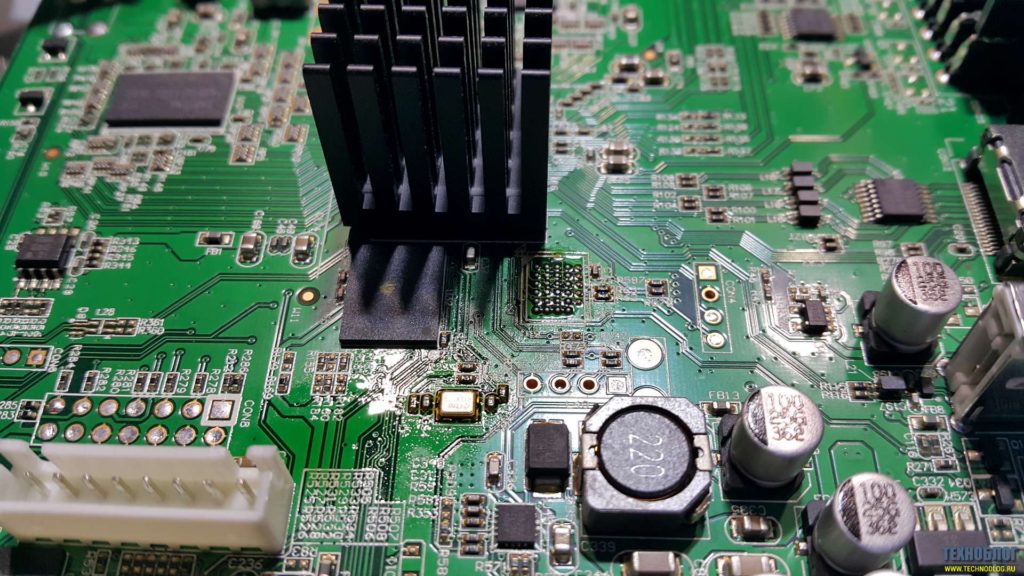
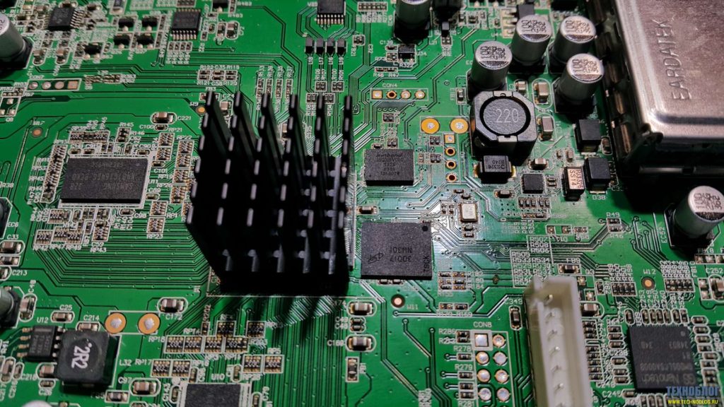
Another very important thing is to check the power supply, since on all modern receivers the power supply is external, they very often fail and the receiver itself may even be working, and the power supply can cause malfunctions from image scattering to the complete inoperability of the receiver, so the first check the integrity of the electrolytic capacitors, they may be swollen and the power supply will not work normally. In our case, the power supply is working, and after we have checked all the supply voltages, we need to flash the receiver, since the software very often does not work correctly, which is why the receiver will not turn on. In this receiver, you need to flash two microcircuits: SPI Flash 25Q32 and Nand Flash MT29F1G08ABADAH4, they are all in a BGA package and you can't just flash them.
| Video (click to play). |
First of all, we flash SPI Flash 25Q32 because I have a Zif socket for it and it is easier to work with it.
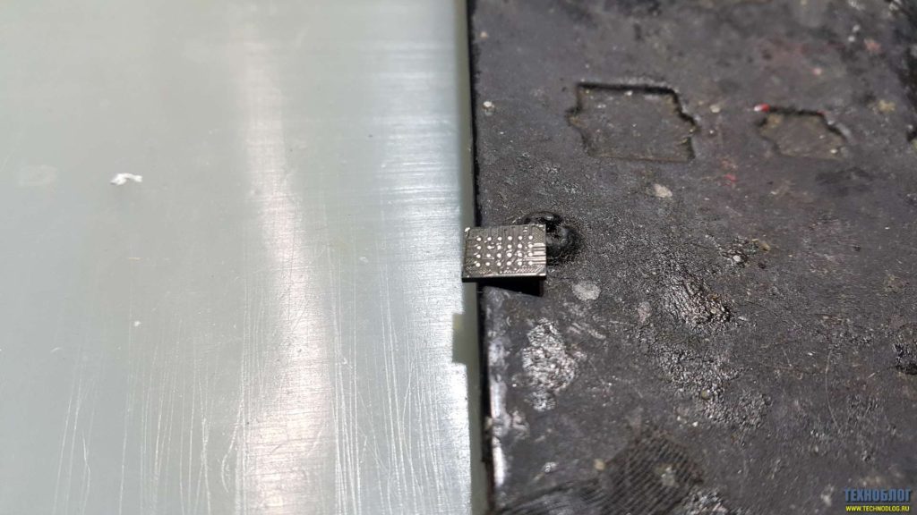
We clean the microcircuit from old balls using copper braid and flux.
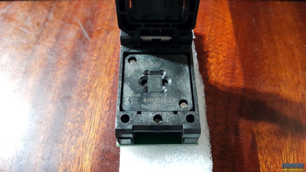
We insert the microcircuit into the Zif socket BGA24 according to the key and close the lid. The design of the Zif socket is made in such a way that when the lid is closed, the needles are raised under the microcircuit for contact with the dimes of the microcircuit.
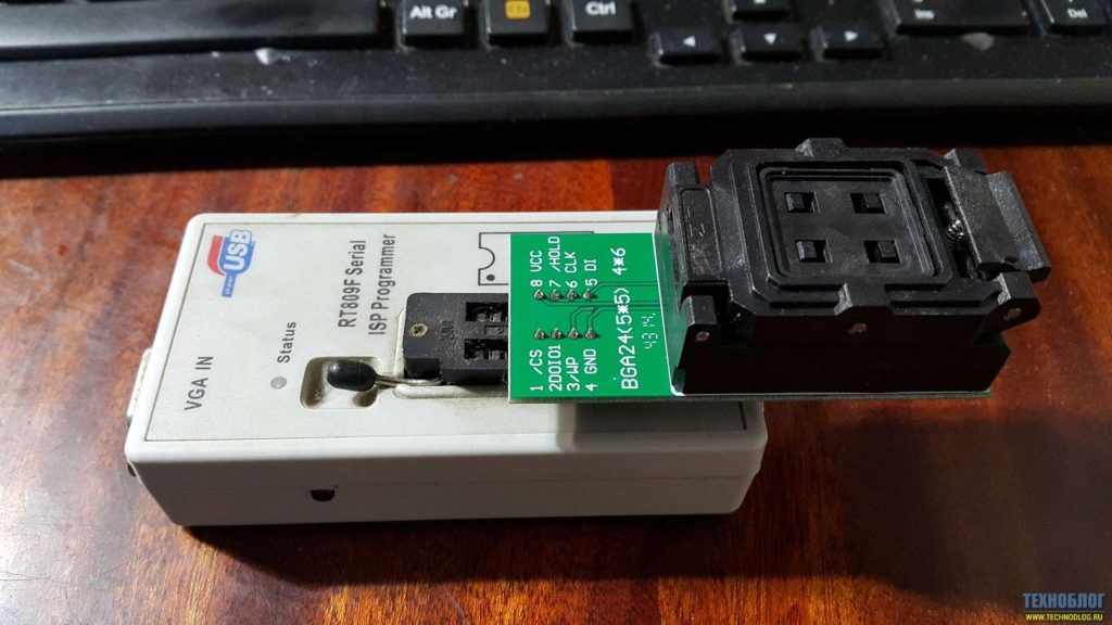
I use the RT809F programmer for SPI Flash 25Q32 firmware, but you can also use another programmer with a corresponding socket.
I did not take pictures using the Nand Flash firmware, I have them, and there is nothing interesting about the whole process in pressing a couple of buttons. After flashing both microcircuits, we roll new balls all together and solder them in place. And do not forget to wash off the remains of the flux, well, for aesthetics.
We check the receiver for inclusion and assemble in the reverse order. Repair price 1500 rubles
Nand microcircuit MT29F1G08ABADAH4 http: //got.by/1t8if7
Chip Spi Flash W25Q32FVTCIG
Zif socket BGA 24
Zif socket adapter for Tsop 48 bga63
Tools and consumables used in this repair.
The main and most common malfunction of all receivers is a malfunction in the power supply and voltage conversion circuit. Also, the modulator often fails due to a short circuit in the coaxial cable from the LNB, although the latest models have good protection against short circuits in the cable, when triggered, the voltage supply to the converter simply stops until the short circuit is eliminated.
And so, our receiver does not show any signs of life, the indicators on the front panel display do not light up, and no twitching of the power plug from the outlet and turning on the toggle switch does not help us (at least that was the case with the device, an example of which is given in this article) ... The first thing we do is pull out the plug from the network and remove the top cover, we need to get to the electronic filling of the device. And here it is important to remember one thing, namely, about the warranty seal, which of course we will break if we remove the cover. Therefore, once again make sure that the warranty period has definitely expired, and under warranty no one will repair it for you. If the warranty is still valid, I advise you to take the receiver to a service center and entrust this matter to a specialist.
Receiver inside:
The electrolytic or oxide capacitor at the input often dries up and fails, which is also a malfunction, not everyone can find such a breakdown either, you need to have at least an initial level of a radio amateur. Usually, defective capacitors are swollen, yellowish, or have a small brown speck on the board at the base of the legs. Also, the serviceability of a capacitor can be determined by comparing its nominal and measured capacitance.
The receiver uses direct current, which is rectified from the AC mains using a diode bridge. Problems with the diode bridge also happen. It is very simple to check diodes, the main function of a semiconductor diode is to pass current in one direction, and not in the other. In my case, the transistor of the primary winding of the transformer turned out to be faulty, it is not difficult to find it, it usually has a radiator to remove heat. I determined the malfunction of the transistor by measuring the voltage at its emitter, it was absent there, the primary winding was not powered, respectively, everything else is de-energized. The transistor cost me 28.5 rubles. Replacing it with a soldering iron, I eliminated the malfunction and the receiver is back in working order. I must say such a breakdown is quite a rare occurrence, usually it all ends with a fuse.
A very common malfunction is a firmware crash. The firmware often crashes, this is usually evidenced by the complete hang of the receiver. In this case, "flashing" will help. I will tell you about one more reason for the malfunction, which may arise due to poor-quality installation. Water in the cable. If the outer insulation of the cable is broken, then water from atmospheric precipitation can get inside, it easily enters the receiver like a hose, sometimes flooding all of its insides. The condition of the cable must be monitored throughout the entire service life of the device.
I have exactly the same set-top box, it does not switch from the remote control (the remote control is working properly). does not show volume indicator when (+) or (-) sound. I don’t know this method will help. What is the volume of the flash drive (or without a difference 4-16 GB reads everything)
reads everything (I have LV, Kingston, and some other)
and even after inserting the USB flash drive, you need to confirm that you need to wait when connecting (but it does not respond to the remote control)
Good day! Such a question is, are there any other goodies, secrets on the 510 receiver via the Internet, for example, I connected the store to no use, I can only proshiorit the store.For me, this is the most successful and stable receiver of all that they are now releasing Prots and the technology alone, well, maybe somewhere doped, and so everything is the same only now flash drives are soldered into new models of licks to rip off more attendants. And so everything is the same, nothing is new, what is 510, which is now only more expensive from the new ones on the market and that's it. Thank you if you take the time to answer. I liked your channel, I will watch your videos in the future and do it often very interesting.
How did you manage to connect it via the Internet? There is no wifi, no ethernet


Certainly . and more than once. I myself SC - we change the boards under warranty, after warranty - only a component
Added by (25/12/2015, 11:47:45)
———————————————
Certainly . and more than once. I myself SC - we change the boards under warranty, after warranty - only a component
Added by (25/12/2015, 11:48:50)
———————————————
Certainly . and more than once. I myself SC - we change the boards under warranty, after warranty - only a component
The receivers of many Tricolor subscribers may stop turning on. How to check the receiver, and what measures to take if a malfunction is detected.
Failure to turn on the receiving equipment may be due to:
- Food intake;
- Switching the TV to a different connector;
- Provider technical work;
- Antenna problems;
- Signal conversion in the converter has stopped;
- Damage to the cable or F-connector;
- Software malfunction;
- Technical malfunctions in the receiver;
- The remote control does not work.
To detect the problem, the user himself can carry out simple actions that involve diagnosing the equipment. Moreover, it is possible to assess the performance of individual links or the entire chain of signal input from the antenna to the receiver.
A Tricolor subscriber, with certain knowledge and skills in electrical circuits or power circuits, can diagnose a broken receiver with his own hands. This will avoid long-term recovery of the receiver in service centers. Having decided to open the equipment, the user should know the special symbols used on the internal elements.

Testing of receivers of the GS series.
A power check is always performed first:
- Is the plug plugged into the outlet;
- Is the power supply defective;
- The correctness of the connection of the power supply to the network;
- Is the wire disconnected from the set-top box, because sometimes children can accidentally take it out;
- The rear panel power switch must be in the on position.
For models of old receivers, the presence of an external power supply is characteristic. The power problem may be due to a malfunction of this element. A Tricolor user can buy a new unit and enjoy watching TV.
On newer models, the power supply system is located inside the case, which complicates the task of repairing. Power may not be supplied due to lost capacitance, the appearance of defective areas on diode bridges. And also a unit that has been in operation for a long time can fail over time. During repairs, you will need to replace the capacitor, which is swollen. Having disassembled the receiver case, immediately distinguish the power supply. By disconnecting it from all the boards, a skilled craftsman will be able to replace the failed elements.
Video: how to replace the power supply unit on the GS8300 receiver
For a simple replacement of the capacitor you will need:
- Soldering iron;
- Screwdriver;
- Soldering flux;
- New capacitor.
When opening a part, the location of the element should be observed. Observe all limits when soldering a new capacitor.
Repairing the power supply will allow the supply of current to resume. If power is supplied, the indication is triggered.Saving the "non-switching" state in the presence of indication is associated with other breakdowns.
When a message appears, the subscriber first checks the likelihood that it is coming from the receiver and not from the TV. The indicators on the receiver are on, and when the buttons are pressed, a response occurs. When calling the Receiver Menu, the device displays a corresponding window. This means that the equipment is correctly connected to the TV, and the error is related to the operation of the receiver.
If the weather is good outside and the provider does not carry out technical work (information about technical work is presented on the company's website or displayed in advance on the Info channel), the message may appear due to the following reasons.
The antenna gets lost under the following conditions:
- Bad weather;
- Poor anchorage;
- Long-term operation;
- Falling heavy object.
An offset of 1 cm causes the signal to disappear. The user needs to analyze the anchoring stiffnesses. If there is a weakness in the attachment, then the adjustment will allow you to achieve the desired signal range. The signal is monitored on the TV display during the period when the "Settings" section in the Receiver Menu is switched on.
After the initial adjustment, it is required to perform a fine tuning operation so that the corresponding scales of the signal parameters are filled at the level of 70-80%. The final step involves securing the pole bolts to the antenna.
If a large object falls on the antenna, it leads to changes in geometry, which implies a change in equipment.
Often, changing the situation on your own does not bring positive results. The cymbal installation and setup wizard will be able to quickly set up the signal. The cost of services depends on the region and place of installation of the equipment.
The subscriber should check the cable from the plate to the receiver. If a breakage site is identified, the wire should be restored using the tools at hand and the F-connector (if one is damaged). Repair stages:
- Cut the wire in the area to be restored;
- Clean up the connecting zones;
- Use F-connector on stripped ends;
- After fixing the connection, screw on the electrical tape.
Operation is not performed on repeated break. A new wire must be used. Some masters, without visually determining the gap, carry out the determination of hidden defects in the cable using a tester.
A cable coming out of the connector may cause no signal. It is required to screw it back under the action of force. The damaged connector can be replaced.
The converter is one of the connecting links in the signal transmission chain. Being constantly on the street, he takes on the effects of weather and the negative influence of the external environment. When purchasing the equipment, warranty service is provided for 1 year. In practice, the part is used for 3-6 years.
An ordinary user will not be able to determine the breakdown. If other variants of the signal deficiency are excluded, the part should be replaced.
A new converter is purchased at the sales office. Replacement instructions:
- Disconnect the element from the mount;
- Fix the new converter without moving the antenna;
- Carry out the range of signal stability on the appropriate scales displayed using the receiver menu on the TV;
- If the settings are out of order, re-adjust the plate.
When calling a support specialist, you will have to pay for the services of identifying the problem and installing a new part if replacement is necessary.
Interference is various objects that appear on the signal transmission line from the satellite to the antenna:
- Tree branches;
- Construction of a high-rise building;
- Snow build-up.
The method for removing the obstacle depends on the object that has arisen. The subscriber can simply reinstall the antenna to make way for the signal.After the transfer, you will need to re-configure the signal.
The performance of the "heads" is revealed after disconnecting the disk (several converters). Then each is connected to the receiver.
If there is no response to the remote control buttons, you should perform the action using the keypad on the receiver itself. If the actions are in progress, then the receiver is functional. After changing the batteries in the remote control, re-check the control with the remote control. Resumption of work did not occur - you need to use a different remote control.
Craftsmen can try to check the operation of the remote control in another way. For this, a mobile phone camera is used. Direct the remote control LED into the switched on camera.
Point the remote at the camera.
While looking at the camera and pressing the buttons, follow the LED indication:
- Stable flashes indicate the serviceability of the remote control;
- The unstable light with interruptions is due to the inoperability of the board;
- Lack of indication implies a malfunction of the remote control or insufficient battery power.
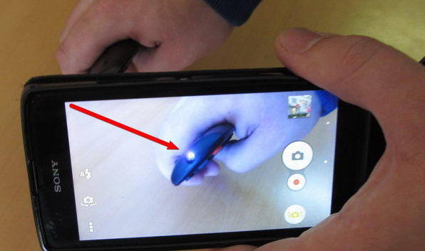
If, after changing the batteries, the LED does not start blinking, then you should buy a new remote control.
Repair of the device in case of rare luminescence is carried out by disassembling the case and cleaning the surface of the board with a damp cloth, soapy water and a dry cloth. After all cleaning operations, dry the parts and assemble the remote control. If the flash does not become constant when viewing through the camera, then a new device is required.
Receiver is a link responsible for receiving a signal and transmitting a video stream. The device may break technical elements or malfunction of the software. The receiver itself has a warranty period (1 year), during which specialists must repair the device.
If a breakdown occurs after the end of the warranty period, then you can carry out an independent diagnosis or give it to a service center. Frequent problems are displayed as errors on the TV screen or the device itself. Please note that these errors are inherent for some models:
- DRE 5000, 7300, 5001;
- DRS 5003;
- GS 7300, 8300, 8300N, 8300M.
For other receivers, there may be a coincidence of errors.
- Failure of the software, which requires a flashing of the device;
- The motherboard is not working properly or is broken.
Replacement of the motherboard is carried out at the repair center. There are daredevils who do it with their own hands. Then you will need to disassemble the receiver and remove the old element. This will void the warranty.
The burning of all indicators and symbols allows us to conclude that there was a software failure. In some cases, the motherboard breaks down. After disassembling the receiver, specialists will be able to determine the true cause of the breakdown. During normal operation of the power supply, the motherboard will be replaced. When other boards are damaged, it is better to buy new equipment, as the cost of repairs can be high.
Receiver motherboard.
The message is translated as "short circuit". The process can take place in several areas. Diagnostic steps:
- If the inscription disappears after disconnecting the antenna wire, then a broken converter, a plate or a short circuit in the wire may be a cause for concern;
- Inspect the wire for a sign of a short circuit by unhooking it from the converter;
- When the wire was pulled out, the message did not disappear - the tuner unit was out of order.
The subscriber can diagnose the breakdown himself.
The updated software may not install correctly. As a result, the receiving device will not turn on. The subscriber must follow the steps of resetting the settings:
- Find and open the "Settings" section in the Receiver Menu;
- Select the command "Reset";
- After confirmation, wait until the end of the process and restart the receiver;
- When turned on, you may need to enter the access code - then the combination "0000" is entered;
- After logging into the system, the necessary parameters are set (language, time, location);
- To install TV channels, you need to perform a search operation and save the changes.
After diagnosing the equipment and excluding all breakdown options, you can contact the service center. First, you need to remember about the availability of a guarantee, if it is still valid. The period is usually set at 12 months. After finding the warranty card, contact the nearest service center. After a quick diagnosis, employees will be able to repair a broken part free of charge.
When the warranty has already expired, you will have to take the product to service under normal conditions. Specialists can open the case and identify the cause. After that, they will offer to carry out repair work, announcing the cost of spare parts and repair procedures. It should be borne in mind that the long service life of the receiver leads to the development of the mortgaged resource. Therefore, for greater savings, it is better to buy a new receiver than to repair an old receiver.
What if the receiver does not turn on after a power outage?
It is necessary to check the functionality of the power supply.
How do you know if the receiver is burnt out?
The device does not respond to the activation of the buttons and the indication does not turn on.
Why does the receiver turn on and off by itself?
The reason may be outdated software, involuntary failure of the power adapter, or problems with contacts.
I am repairing Tricolor receivers and did not expect that my personal B210 receiver, which I recently received when exchanging “old” equipment for “new”, would break down after only half a year.
The diagnosis is simple: “Does not turn on”, “does not light up in red and green”
I am an inquisitive person and therefore did not become wise with a guarantee.
When measuring the supply voltage directly on the board, the 12 V voltage drops to 0.5V. Although the unit separately gave out the voltage as it should. A short circuit call showed that there was no short circuit at the receiver input. How so?
This means that the voltage sags on the secondary power circuits, after the pulse-width modulators.
So it is, it's all about low-quality parts.
After the PWM, the SMD capacitor shorted to 25μF.
Written by Administrator on 07 December 2011.
Hello, today we will try to fix the Tricolor TV receiver with our own hands. Many faced such a problem when the warranty (usually 12 months) expired and the receiver suddenly failed. A new one is expensive, and in most cases the repair will not be difficult and will cost a penny, if you are even a little friends with a soldering iron, the main and most common faults are easy to fix yourself. Let us consider such a repair using the example of another GS-8300 N receiver from the Tricolor TV company. It must be said that the device is not of the best quality, and Tricolor TV is certainly not worth the money that Tricolor TV takes for it. But, nevertheless, the number of subscribers is large and not all of them work for a long time and regularly.
The main and most common malfunction of all receivers is a malfunction in the power supply and voltage conversion circuit. Also, the modulator often fails due to a short circuit in the coaxial cable from the LNB, although the latest models have good protection against short circuits in the cable, when triggered, the voltage supply to the converter simply stops until the short circuit is eliminated.
And so, our receiver does not show any signs of life, the indicators on the front panel display do not light up, and no twitching of the power plug from the outlet and turning on the toggle switch does not help us (at least that was the case with the device, an example of which is given in this article) ... The first thing we do is pull out the plug from the network and remove the top cover, we need to get to the electronic filling of the device. And here it is important to remember one thing, namely, about the warranty seal, which of course we will break if we remove the cover. Therefore, once again make sure that the warranty period has definitely expired, and under warranty no one will repair it for you. If the warranty is still valid, I advise you to take the receiver to a service center and entrust this matter to a specialist.


The electrolytic or oxide capacitor at the input often dries up and fails, which is also a malfunction, not everyone can find such a breakdown either, you need to have at least an initial level of a radio amateur. Usually, defective capacitors have a yellowish appearance, or a small brown speck on the board at the base of the legs. Also, the serviceability of a capacitor can be determined by comparing its nominal and measured capacitance.
The receiver uses direct current, which is rectified from the AC mains using a diode bridge. Problems with the diode bridge also happen. It is very simple to check diodes, the main function of a semiconductor diode is to pass current in one direction, and not in the other. In my case, the transistor of the primary winding of the transformer turned out to be faulty, it is not difficult to find it, it usually has a radiator to remove heat. I determined the malfunction of the transistor by measuring the voltage at its emitter, it was absent there, the primary winding was not powered, respectively, everything else is de-energized. The transistor cost me 28.5 rubles. Replacing it with a soldering iron, I eliminated the malfunction and the receiver is back in working order. I must say such a breakdown is quite a rare occurrence, usually it all ends with a fuse.
A very common malfunction is a firmware crash. The firmware often crashes, this is usually evidenced by the complete hang of the receiver. In this case, "flashing" will help. I also want to say about another cause of the malfunction, which may arise due to poor-quality installation. Water in the cable. If the outer insulation of the cable is broken, then water from atmospheric precipitation can get inside and it easily enters the receiver like a hose, sometimes flooding all of its insides. The condition of the cable must be monitored throughout the entire service life of the device.
Electronic devices surround us everywhere: on the street, at work, at home. With the rapid growth and availability of satellite television to the general public, a wide range of satellite equipment has emerged for the general public. These are satellite receivers, conditional access modules, antennas, converters, etc. Whether we like it or not, sooner or later breakdowns occur with them, which cause us to feel the loss of our beloved thing.
You should not despair - for this there are service centers that you can turn to and they will help you to bring your equipment back to life.
Breakdowns of equipment occur for various reasons - voltage drops, failure of various nodes, wear and tear of the equipment itself from its venerable age, you can also note the incompetence of the owners themselves, for example, improper replacement of software in satellite and cable receivers.
Power supply failure is perhaps the most common type of digital terminal failure. It arises for various reasons: a poor-quality supply network (see photo), poor-quality radio components were used, especially this is de facto in Chinese technology.
Also, this can include violation of operation, dust, dirt, as a result of this, the thermal regime is not correct (see photo).
A service center is a structural unit within a company. He is responsible not only for the repair and maintenance of the products sold by our company, but also for the repair (including warranty) of satellite equipment from other companies. Our clients are not only individuals - users, but also equipment dealers who seek to save their customers from the problems associated with the repair and maintenance of receivers. Our flexible corporate customer policy allows us to provide adequate service and meet the interests of all customer groups. This is more than 1000 units of equipment per month. To carry out such large volumes, of course, allows the professionalism of the employees, the equipment of the service center with professional equipment, tools and technical documentation. Therefore, in our service center we carry out high-complexity repairs: for example, replacing processors in BGA cases. Repair takes place in the shortest possible time.
The supply department, in addition to its main function - the purchase of equipment, is also engaged in meeting the needs of the service center, purchasing components necessary for repair. And here it is worth noting that the selection and purchase of components for repair occurs according to the following criterion: the quality of parts comes first, their price comes second, but due to the large volumes of supplies of parts, the price ultimately remains low.
All orders are processed electronically and registered in the database. This makes it easy to track the various stages of the repair process. A guarantee is provided for the work performed.
Of course, unforeseen moments happen - for some reason, the repair is delayed. This usually happens due to the lack of some scarce radio component. Sometimes repairs require a complete replacement of the motherboard, and this repair part is not always available. In this case, we are trying to find some acceptable solution together with the client, taking into account his wishes, combined with our capabilities.
At autopsy, found out of order:
- network capacity C5 - 47µFx400V
- Q1 - CS2N60F
- R8, R11, R13 - each with a nominal value of 3 Om (frame size 1206)
- R9 - 47 Om (1206)
- U1 - it was not possible to determine its type by the marking on the case.
According to the table on identification and selection of analogs https://my.housecope.com/wp-content/uploads/ext/2561/ic_power/, the last part was replaced with SG6848 with minimal interference with the factory circuit.
Dismantling: (circled in red in the photo)
- U1
- R8, R11, R13 - 3 Om (1206)
- R3, R6 (one of them is possible) - 1 MOm (1206)
- C3 - 68nF
- R25 - 3.6 kOm (0805)
- R26 - 10 kOm (0805)
Install:
- instead of U1 - SG6848
- instead of R8, R11, R13 - one 1.8 Om x 0.5W resistor (the usual output one, since I did not find the smd of the required rating))
- instead of C3 a 100 kOm resistor (1206)
- instead of R26 a 33 kOm resistor
- instead of R25, we select a resistor in the range of 10-12 kOm, monitoring the voltage 3V3 at the cathode VD8. I settled on the nominal 11 kOm, U = 3.36V (at 10 kOm U = 3.28V, at 12 kOm U = 3.41V)
SSS4N60B (TO-220F package) was installed instead of the burnt-out Q1
On Telesputnik posted a diagram of the power supply unit.
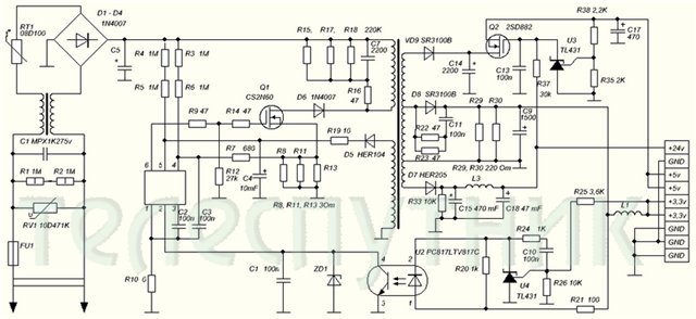
There are inaccuracies:
1. The lower terminal of the primary winding must be connected
to the junction point of the anode D6 and drain Q1
2. Positional designations C2 and C3 are incorrect. C3 must be connected to the 3rd pin
U1, C2 to the 4th pin of U1.
3. Nominal C3 = 68nF
4. In the diagram, there are two capacitors C1
5. Missing C12
6. The primary land is designated in the same way as the secondary one.
7. Missing C8
8.Q2 - MOSFET NTD14N03R
9.Rated C11 = 2200pF
10. Type D8 = SR560
11. Positional designations U3 and U4 are incorrect - they must be reversed.
12. Denomination C5 = 47µF
The receiver turns on, the LNB has 18 volts. There is no video signal, it gets very hot (the finger does not hold) stv 6419 .. because of it there can be no video? there is no other point? (in the sense that more video signal is not to be taken from?) the receiver switches channels ..
GS 8300N receiver there is no video and audio signal through scart to the TV, the channels are switched on the receiver panel.
the video signal from the STi5119ALC chip can be checked with an oscilloscope at the control point opposite the capacitor C117, then it comes to the resistor R87 and is transmitted to the capacitor C129 and then goes to the STV6419 microcircuit from it there is no output to R91, the culprit is not 12 volts on the board, respectively, there is no power + 12V on the 3rd leg STV6419, a 12 volt Zener diode D3 is faulty near the power connector
There was such an answer: if you use only composite video signal, most likely it can be simply thrown out (replaced with a jumper). And where to put the jumper? if that's the right advice ..
Defective VD3 (VD3 zener diode 12 V) on the motherboard next to the power connector.
Zener diode brand and parameters:
Power supply + 12V for 3rd leg STV6419.
Along the chain: XP5 connector 9th leg -> R81 (300 Om) + Zener diode VD3 (12V) = stabilizer + 12V -> L3 -> 3rd leg STV6419.
Zener diode analog:
VD3 STV6419 similar Zener diode (SMD) did not find. Put a 0.5 watt glass zener diode the size of a diode kd522 ... While the flight is normal.
If replacing the zener diode did not help:
After the thunderstorm, 6419 swelled. After the replacement, the image did not appear, but when checking the strapping, two resistors were cut off, R91, R95... I replaced it, and it worked.
One more problem:
And yet, instead of 13, 18 Volts, 24V was running on the LNB. Replacement required DA1 (LM317T)... And that's it, the flight is normal
The same situation with the GS-8304 receiver:
After 5 years of operation, the GS-8304 suddenly stopped broadcasting, although the indication is working properly.
Zener diode struck at short circuit. Zener diode brand MMZE5242B.
If the following message appears when inserting a smart card: “Smart card is incorrect Smart card is not inserted“
, then the fastest on the receiver board is the smartcard controller TDA8024 .
Pointed with a red arrow:We change it and rejoice
When soldering with a hairdryer, you need to put some kind of nib. the gasket between the connector and the micro, since they are very close and the plastic is very fast-melting.Operating voltages on the board:
L53-5.4v
L2 -5.4v
L8 -3.4v
L11-1.2v
L26-12v
L6 -1.8v
L60-3.3v
L20-5.4v
L66-5.35v
L71-0v
L3-12.1v
L15-5.35v
L16-2.5v
L29-5.35v
L12-3.3v
L52-3.3v
L81-5.35v
choke over L81 towards 1.2v connectors
the next one is slightly to the left of 3.3v and even to the left of 1.2v
L64-5.35v
L23-12v
L28-3.3v
L35-3.3v
L22-5.35v
L7 -1.2vMessage :
NO CHANNEL FOUND!
CHECK ANTENNA AGAIN.If such a garbage happened and the flashing did not help, then the fastest of all is an iron problem:
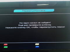
In my case, the receiving module turned out to be the culprit:
(not an isolated case, with this problem - through one and all with this disease)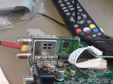
And upon opening it, flooding and corrosion were found:
Plus, after removing the module, the track was damaged:
The module includes: m88ts2022 (DVB-S2 / DVB-S / ABS-S tuner) and M88DS3103 (DVB-S2 / S demodulator)
Accordingly, I had to replace the module from the donor. and throw the track MGTF - ohm.

Video (click to play). Only the radio works (as an option), does not reset to factory settings, freezes and turns off, is not flashed via USB, is not updated in any way.

