In detail: do-it-yourself repair of the tricolor gs e501 receiver from a real master for the site my.housecope.com.
In this manual, we will get acquainted with the tricolor twins. These are GS E501 and GS C591 - legalized cardsharing.
We will read dumps from them.
Let's start our acquaintance with the GS C591. There is an Inboard serial flash and Spansion Nand Flash.
First, let's turn to the serial, then we'll get to Nand Flash.
The interfering part to the left of the memory is removed by hand. You just need to make a little effort.
For better soldering, you can drip a little flux. Then I use a hot air gun and, helping with tweezers or something similar, we solder the memory from the board.
After removing the serial memory, go to the Nand memory.
Next, take a soldering iron and collect the remaining solder.
Anyone with a soldering station that is not induction may not heat the surface. In this case, it is better to remove the solder immediately after removing the flash drive. Since the surface will be more or less warmed up, the soldering iron will not stick to the nickels.
In induction soldering stations, this problem disappears by itself. The soldering iron warms up the surface very well.
Now we remove the remnants of the solder on the dimes with a braid.
Do not forget to wipe the contact pads. Thus, we get ready-made pads for soldering stitched flash drives, also cleaned of solder residues.
Let's move on to rolling the balls.
In order not to waste a lot of balls, you can take a small part of the balls on your finger and gently pour them onto the flush. Then spread them out gently with tweezers.
We turn to the second receiver and do the same procedures with it. We solder, remove the remnants of the solder, clean the contact pads. Then we prepare flash drives for rolling balls.
| Video (click to play). |
In addition to the already familiar flash drives, here you need to solder the crypto processor flash drive.
It must also be counted. Since in the event of force majeure (for example, moisture ingress), it may fail.
At the end of reading the dumps (a rather lengthy process), the following was obtained. We counted dumps from both devices. In the process, Nand flash drives were replaced with places and sewn back with read dumps. The receiver started perfectly at the end of all the manipulations.
The only condition is that the dump must be read correctly and the flash drive must be functional. So we had a problem with one flash drive - one sector did not answer. I had to replace it.
Serial flash drives and flash drives of the crypto processor are flashed on the adapter, as in the image below.
Its name is AE-B24-25XX-2.
The process of the firmware itself can be found in the video instructions on the Internet. There is nothing supernatural there. The only thing you need to pay attention to is setting the settings for reading and writing Nand flash drives. Similar information is available on the website of the programmer manufacturer.
There you can familiarize yourself with the structure of the flash drive. With the way it is read, copied and programmed. Everything is described in accessible language.
From the beginning of summer 2014, active advertising promotion of a new set of equipment for receiving Tricolor TV began - client-server set GS E501 + GS C591... Oddly enough, there are practically no complaints about the operation of the kit itself. Everything works stably. Occasionally the server receiver of the GS E501 kit freezes, but this can be cured by overloading the power supply. And yet, the operation has revealed one drawback of this set of equipment….
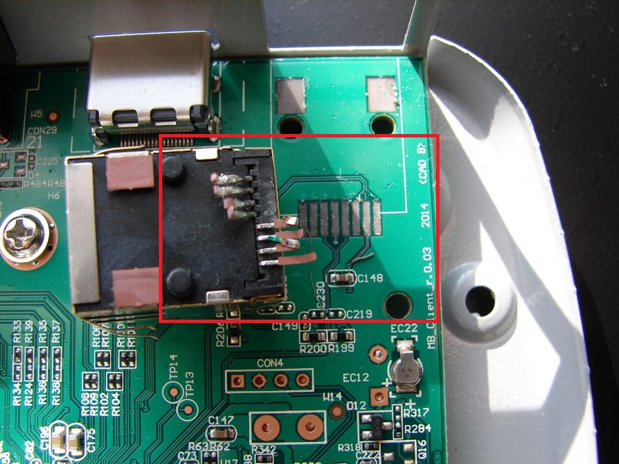
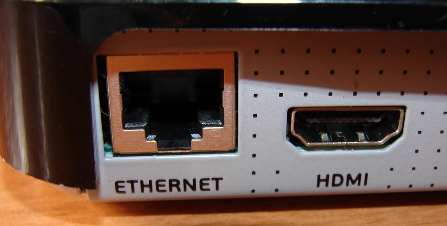
And this disadvantage applies to the client receiver of the kit - GS C591. Its problem is that the LAN connector, through which the client receiver receives all the information from the server, is weakly soldered to the motherboard and if you press it too hard / for example, when you connect a twisted pair cable to the receiver / it just falls off the receiver's motherboard ...And if you try, then it does not just fall off, but also tears off the conductive tracks from the boardwhich are soldered to it.
A customer contacted us in the service, who just did his best - the LAN connector was not only torn off from the receiver board, but the conductive tracks were also torn off. /see photo/
 On the client receiver Tricolor GS_C591, the conductive paths are damaged
When the case of the GS_C591 receiver was disassembled, it turned out that the LAN connector in it just dangles like a rattle - at least it didn’t fall out of the case and was not lost.
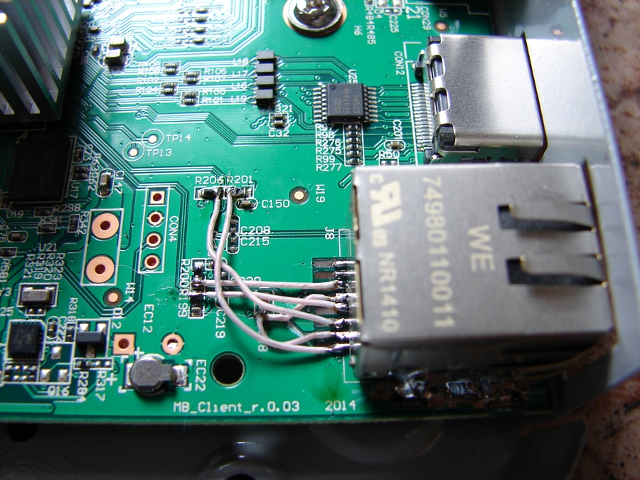
While repairing GS_C591, soldering the torn off LAN connector itself turned out to be a simple matter, but I had to tinker with the restoration of conductive paths... The tracks were damaged and it was necessary to ring them in order to understand from which contact on the LAN connector to which element of the motherboard to transmit the signal.
After it became clear what it was interacting with, the LAN connector was soldered and new conductive tracks were soldered - it turned out, albeit not entirely aesthetically pleasing, but positive result achieved - the client receiver for the Tricolor GS C591 again receives data packets from the server receiver and works great.
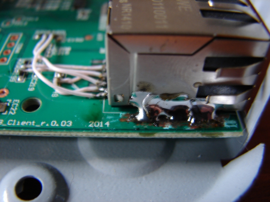 Repair of the GS_C591 receiver - soldering the LAN connector with a couple of good solder seams
The Tricolor GS C591 receiver was repaired by our specialist for laptop repair in Krasnodare - for him, the work of restoring the motherboard is typical and does not cause difficulties.
Repairs are carried out out of warranty, on a paid basis. In the same case, if you have a correctly completed warranty card, then in order to carry out free warranty repairs during the entire warranty period, you should contact an authorized service center in Krasnodar.
The main and most common malfunction of all receivers is a malfunction in the power supply and voltage conversion circuit. Also, the modulator often fails due to a short circuit in the coaxial cable from the LNB, although the latest models have good protection against short circuits in the cable, when triggered, the voltage supply to the converter simply stops until the short circuit is eliminated.
And so, our receiver does not show any signs of life, the indicators on the front panel display do not light up, and no twitching of the power plug from the outlet and turning on the toggle switch does not help us (at least that was the case with the device, an example of which is given in this article) ... The first thing we do is pull out the plug from the network and remove the top cover, we need to get to the electronic filling of the device. And here it is important to remember one thing, namely, about the warranty seal, which of course we will break if we remove the cover. Therefore, once again make sure that the warranty period has definitely expired, and under warranty no one will repair it for you. If the warranty is still valid, I advise you to take the receiver to a service center and entrust this matter to a specialist.
Receiver inside:
The electrolytic or oxide capacitor at the input often dries up and fails, which is also a malfunction, not everyone can find such a breakdown either, you need to have at least an initial level of a radio amateur. Usually, defective capacitors are swollen, yellowish, or have a small brown speck on the board at the base of the legs. Also, the serviceability of a capacitor can be determined by comparing its nominal and measured capacitance.
The receiver uses direct current, which is rectified from the AC mains using a diode bridge. Diode bridge problems also happen. It is very simple to check diodes, the main function of a semiconductor diode is to pass current in one direction, and not in the other. In my case, the transistor of the primary winding of the transformer turned out to be faulty, it is not difficult to find it, it usually has a radiator to remove heat. I determined the malfunction of the transistor by measuring the voltage at its emitter, it was absent there, the primary winding was not powered, respectively, everything else is de-energized. The transistor cost me 28.5 rubles. Replacing it with a soldering iron, I fixed the malfunction and the receiver is back in working order. I must say such a breakdown is quite a rare occurrence, usually it all ends with a fuse.
A very common malfunction is a firmware crash. The firmware often crashes, this is usually evidenced by the complete hang of the receiver. In this case, "flashing" will help. I will tell you about one more reason for the malfunction, which may arise due to poor-quality installation. Water in the cable. If the outer insulation of the cable is broken, then water from atmospheric precipitation can get inside, it easily enters the receiver like a hose, sometimes flooding all of its insides. The condition of the cable must be monitored throughout the entire service life of the device.
Written by Administrator on 07 December 2011.
Hello, today we will try to fix the Tricolor TV receiver with our own hands. Many faced such a problem when the warranty (usually 12 months) expired and the receiver suddenly failed. A new one is expensive, and in most cases the repair will not be difficult and will cost a penny, if you are even a little friends with a soldering iron, the main and most common faults are easy to fix yourself. Let's consider such a repair using the example of another GS-8300 N receiver from the Tricolor TV company. I must say that the device is not of the best quality, and of course, Tricolor TV is not worth the money that Tricolor TV takes for it. But, nevertheless, the number of subscribers is large and not all of them work for a long time and regularly.
The main and most common malfunction of all receivers is a malfunction in the power supply and voltage conversion circuit. Also, the modulator often fails due to a short circuit in the coaxial cable from the LNB, although the latest models have good protection against short circuits in the cable, when triggered, the voltage supply to the converter simply stops until the short circuit is eliminated.
And so, our receiver does not show any signs of life, the indicators on the front panel display do not light up, and no twitching of the power plug from the outlet and turning on the toggle switch does not help us (at least that was the case with the device, an example of which is given in this article) ... The first thing we do is pull out the plug from the network and remove the top cover, we need to get to the electronic filling of the device. And here it is important to remember one thing, namely, about the warranty seal, which of course we will break if we remove the cover. Therefore, once again make sure that the warranty period has definitely expired, and under warranty no one will repair it for you. If the warranty is still valid, I advise you to take the receiver to a service center and entrust this matter to a specialist.
The electrolytic or oxide capacitor at the input often dries up and fails, which is also a malfunction, not everyone can find such a breakdown either, you need to have at least an initial level of a radio amateur.Usually, defective capacitors have a yellowish appearance, or a small brown speck on the board at the base of the legs. Also, the serviceability of a capacitor can be determined by comparing its nominal and measured capacitance.
The receiver uses direct current, which is rectified from the AC mains using a diode bridge. Diode bridge problems also happen. It is very simple to check diodes, the main function of a semiconductor diode is to pass current in one direction, and not in the other. In my case, the transistor of the primary winding of the transformer turned out to be faulty, it is not difficult to find it, it usually has a radiator to remove heat. I determined the malfunction of the transistor by measuring the voltage at its emitter, it was absent there, the primary winding was not powered, respectively, everything else is de-energized. The transistor cost me 28.5 rubles. Replacing it with a soldering iron, I eliminated the malfunction and the receiver is back in working order. I must say such a breakdown is quite a rare occurrence, usually it all ends with a fuse.
A very common malfunction is a firmware crash. The firmware often crashes, this is usually evidenced by the complete hang of the receiver. In this case, "flashing" will help. I also want to say about another cause of the malfunction, which may arise due to poor-quality installation. Water in the cable. If the outer insulation of the cable is broken, then water from atmospheric precipitation can get inside and it easily enters the receiver like a hose, sometimes flooding all of its insides. The condition of the cable must be monitored throughout the entire service life of the device.
Electronic devices surround us everywhere: on the street, at work, at home. With the rapid growth and availability of satellite television to the general public, a wide range of satellite equipment has emerged for the general public. These are satellite receivers, conditional access modules, antennas, converters, etc. Whether we like it or not, sooner or later breakdowns occur with them, which cause us to feel the loss of our beloved thing.
You should not despair - for this there are service centers that you can turn to and they will help you to bring your equipment back to life.
Breakdowns of equipment occur for various reasons - voltage drops, failure of various nodes, wear and tear of the equipment itself from its venerable age, you can also note the incompetence of the owners themselves, say, improper replacement of software in satellite and cable receivers.
Power supply failure is perhaps the most common type of digital terminal failure. It arises for various reasons: a poor-quality supply network (see photo), poor-quality radio components were used, especially this is de facto in Chinese technology.
Also, this can include a violation of operation, dust, dirt, as a result of this, the thermal regime is not correct (see photo).
A service center is a structural unit within a company. He is responsible not only for the repair and maintenance of products sold by our company, but also for the repair (including warranty) of satellite equipment from other companies. Our clients are not only individuals - users, but also equipment dealers who seek to save their customers from the problems associated with the repair and maintenance of receivers. Our flexible corporate customer policy allows us to provide adequate service and meet the interests of all customer groups. This is more than 1000 units of equipment per month. To carry out such large volumes, of course, allows the professionalism of the employees, the equipment of the service center with professional equipment, tools and technical documentation. Therefore, in our service center we carry out high-complexity repairs: for example, replacing processors in BGA cases. Repair takes place in the shortest possible time.
The supply department, in addition to its main function - the purchase of equipment, is also engaged in meeting the needs of the service center, purchasing components necessary for repair.And here it is worth noting that the selection and purchase of components for repair is carried out according to the following criterion: the quality of parts comes first, their price comes second, but due to the large volumes of supplies of parts, the price ultimately remains low.
All orders are processed electronically and registered in the database. This makes it easy to track the various stages of the repair process. A guarantee is provided for the work performed.
Of course, unforeseen moments happen - for some reason, the repair is delayed. This usually happens due to the lack of some scarce radio component. Sometimes repairs require a complete replacement of the motherboard, and this repair part is not always available. In this case, we are trying to find some acceptable solution together with the client, taking into account his wishes, combined with our capabilities.
At autopsy, found out of order:
- network capacity C5 - 47µFx400V
- Q1 - CS2N60F
- R8, R11, R13 - each with a nominal value of 3 Om (frame size 1206)
- R9 - 47 Om (1206)
- U1 - it was not possible to determine its type by the marking on the case.
According to the table on identification and selection of analogs https://my.housecope.com/wp-content/uploads/ext/2561/ic_power/, the last part was replaced with SG6848 with minimal interference with the factory circuit.
Dismantling: (circled in red in the photo)
- U1
- R8, R11, R13 - 3 Om (1206)
- R3, R6 (one of them is possible) - 1 MOm (1206)
- C3 - 68nF
- R25 - 3.6 kOm (0805)
- R26 - 10 kOm (0805)
Install:
- instead of U1 - SG6848
- instead of R8, R11, R13 - one 1.8 Om x 0.5W resistor (the usual output one, since I did not find the smd of the required rating))
- instead of C3 a 100 kOm resistor (1206)
- instead of R26 a 33 kOm resistor
- instead of R25, we select a resistor in the range of 10-12 kOm, monitoring the voltage 3V3 at the cathode VD8. I settled on the nominal 11 kOm, U = 3.36V (at 10 kOm U = 3.28V, at 12 kOm U = 3.41V)
SSS4N60B (TO-220F package) was installed instead of the burnt-out Q1
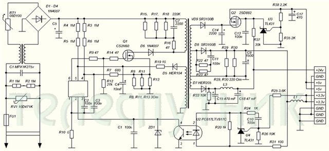
On Telesputnik posted a diagram of the power supply unit.
There are inaccuracies:
1. The lower terminal of the primary winding must be connected
to the junction point of the anode D6 and drain Q1
2. Positional designations C2 and C3 are incorrect. C3 must be connected to the 3rd pin
U1, C2 to the 4th pin of U1.
3. Nominal C3 = 68nF
4. In the diagram, there are two capacitors C1
5. Missing C12
6. The primary land is designated in the same way as the secondary one.
7. Missing C8
8.Q2 - MOSFET NTD14N03R
9.Rated C11 = 2200pF
10. Type D8 = SR560
11. Positional designations U3 and U4 are incorrect - they must be reversed.
12. Denomination C5 = 47µF
The receiver turns on, the LNB has 18 volts. There is no video signal, it gets very hot (the finger does not hold) stv 6419 .. because of it there can be no video? there is no other point? (in the sense that more video signal is not to be taken from?) the receiver switches channels ..
GS 8300N receiver there is no video and audio signal through scart to the TV, the channels are switched on the receiver panel.
the video signal from the STi5119ALC chip can be checked with an oscilloscope at the control point opposite the capacitor C117, then it comes to the resistor R87 and is transmitted to the capacitor C129 and then goes to the STV6419 microcircuit from it there is no output to R91, the culprit is not 12 volts on the board, respectively, there is no power + 12V on the 3rd leg STV6419, a 12 volt Zener diode D3 is faulty near the power connector
There was such an answer: if you use only composite video signal, most likely it can be simply thrown out (replaced with a jumper). And where to put the jumper? if that's the right advice ..
Defective VD3 (VD3 zener diode 12 V) on the motherboard next to the power connector.
Zener diode brand and parameters:
Power supply + 12V for 3rd leg STV6419.
Along the chain: XP5 connector 9th leg -> R81 (300 Om) + Zener diode VD3 (12V) = stabilizer + 12V -> L3 -> 3rd leg STV6419.
Zener diode analog:
VD3 STV6419 similar Zener diode (SMD) did not find. Put a 0.5 watt glass zener diode the size of a diode kd522 ... While the flight is normal.
If replacing the zener diode did not help:
After the thunderstorm, 6419 swelled. After the replacement, the image did not appear, but when checking the strapping, two resistors were cut off, R91, R95... I replaced it, and it worked.
One more problem:
And yet, instead of 13, 18 Volts, 24V was running on the LNB. Replacement required DA1 (LM317T)... And that's it, the flight is normal
The same situation with the GS-8304 receiver:
After 5 years of operation, the GS-8304 suddenly stopped broadcasting, although the indication is working properly.
Zener diode struck at short circuit. Zener diode brand MMZE5242B.
In case of static breakdown of LED-IR-buttons D1 of the P115VM39 microcircuit, it is changed to the original without the sawn-off inscription - TM1668 (from GS8306 and other older models, the LED-IR chip does not fit, KTs746SU - STLED316S).
Potentially, 4 buttons and 4 diodes can be soldered into the second module (prefix C591) according to the scheme from the E501 and they will work the same as in the E501.
The E501 receiver has an unsoldered SW2 reset button on the board, a COM-TTL con4 connector (1-tx log transmission, 2-rx, 3-gnd, 4-3v3) for diagnostics via a com port. Unidentified connectors: con30 (14 pin), con1, j2, j3 (4 pin).
E501 receivers with a “cyclic boot” breakdown (we immediately check the working 100% PSU and exclude PSU degradation from this list), from failure to reach the indicator test and reboot after 30 seconds - until the zero info channel is displayed and reboot after 2 minutes (does not have time to boot before the commands are executed from buttons or remote control). In some places it has a hardware dump of balls of chips (after warming up or under pressure, it turns on).
One of the driven C591 (rebooted after 3-5 minutes, including after switching channels, did not run, hung by 25-28%) managed to get into the menu and make a full reset. After that, it was sewn and works fine.
I tried all the options for clamping the power P- P + V- V + buttons when turning on the reboot E501, does not reset the settings. The port does not respond to TTL-com.
U32 - Spansion ML02G100BHI00 3PE17 NW312 BGA63, U19, U41 - Winbond 25Q32FVC1G, U39 - GS Nanotech GMDDSLCSA000B, U10, U11 - Samsung K4B1G16460
BP FP06M024 0 0 0 3.3 3.3 5 0 12 22 28 GS 7300
BP FP09T001 0 0 0 3.3 3.3 5 5 0 24 GS 8300N
Site about Tricorol TV. Services, package review, channel list, news, promotions and equipment reviews, discussion. Help for subscribers. Forum Tricolor TV. Official site, main page tricolor.tv
Users browsing this forum: Google Adsense [Bot], Trident and 2 guests
It is currently Oct 19, 2018 3:16 pm
"Site rules" Read necessarily in order to avoid conflicts and misunderstandings.
Reception of a satellite TV signal is carried out using the following special equipment: the main receiver GS E501 - the server, and the auxiliary receiver GS C591 - the client. Both main and auxiliary receivers can be used independently. Both devices are also configured separately. If you are faced with a problem that gs e501 boot will not boot or turn on, what to do in this situation?
Satellite signal successors are designed and manufactured to ensure maximum user protection during the operation of these devices.
Carefully study the safety rules for handling satellite receivers before using them for the first time.
First of all, you need to clearly understand the rules for using the device. Compliance with the following rules will ensure an increase in the service life of satellite signal receivers.
The receiver must be installed in a place that ensures its stable stability. It is important not to drop the receiver in order to avoid damage to it and possible injury to people. Do not expose the receiver to bright sunlight for extended periods of time.
- It is not allowed to use the connectors for other purposes specified in this manual;
- The use of connectors for battery charging is prohibited. Interface connectors cannot serve as power supplies for electrical appliances.
- External devices may only be connected to the receiver when it is disconnected from the power supply. An exception to this rule is the connection of USB devices.
- The smart card must be removed and inserted into the turned off receiver. Otherwise, the device may malfunction.
Operation of the receiver in buildings and structures with low air temperature and high humidity is not allowed. The following climatic parameters of operation are admissible:
- Relative humidity - ≤80%;
- Indoor temperature - from 5 ºC to 40 ºC.
The reasons for this problem may be as follows:
- A short circuit in the network, which led to a malfunction of the device software. The solution to the problem is to rewrite the receiver software. Such an operation is carried out using a special programmer.
- The motherboard is receiving incorrect voltage values.
- Failure of the motherboard.
We can easily eliminate the indicated malfunctions right at your home if you live in Moscow or the neighboring regions.To do this, you need to take one simple step: fill out an application on the website or report a problem using the phone numbers indicated in the contacts.
The receivers of many Tricolor subscribers may stop turning on. How to check the receiver, and what measures to take if a malfunction is detected.
Failure to turn on the receiving equipment may be due to:
- Food intake;
- Switching the TV to a different connector;
- Provider technical work;
- Antenna problems;
- Signal conversion in the converter has stopped;
- Damage to the cable or F-connector;
- Software malfunction;
- Technical malfunctions in the receiver;
- The remote control does not work.
To detect the problem, the user himself can carry out simple actions that involve diagnosing the equipment. Moreover, it is possible to assess the performance of individual links or the entire chain of signal input from the antenna to the receiver.
A Tricolor subscriber, with certain knowledge and skills in electrical circuits or power circuits, can diagnose a broken receiver with his own hands. This will avoid long-term recovery of the receiver in service centers. Having decided to open the equipment, the user should know the special symbols used on the internal elements.
Testing of receivers of the GS series.
A power check is always performed first:
- Is the plug plugged into the outlet;
- Is the power supply defective;
- The correctness of the connection of the power supply to the network;
- Is the wire disconnected from the set-top box, because sometimes children can accidentally take it out;
- The rear panel power switch must be in the on position.
For models of old receivers, the presence of an external power supply is characteristic. The power problem may be due to a malfunction of this element. A Tricolor user can buy a new unit and enjoy watching TV.
On newer models, the power supply system is located inside the case, which complicates the task of repairing. Power may not be supplied due to lost capacitance, the appearance of defective areas on diode bridges. And also a unit that has been in operation for a long time can fail over time. During repairs, you will need to replace the capacitor, which is swollen. Having disassembled the receiver case, you can immediately distinguish the power supply. By disconnecting it from all the boards, a skilled craftsman will be able to replace the failed elements.
Video: how to replace the power supply on the GS8300 receiver

