In detail: do-it-yourself steering rack repair from a real master for the site my.housecope.com.
Please note that the conversion of a car by a non-specialist can lead to serious consequences and is simply illegal in some countries.
I installed myself a rack 2108.
First I measured the brand-rail and 2108.
The brand-rail has a movement from lock to lock of about 11 cm and 3.2 turns of the steering wheel.
2108 has 3.5 revolutions, but the movement is about 15 cm.
It turns out with the eighth rack a sharper steering.
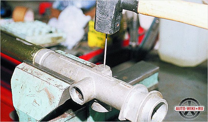
Then he fitted the rail to the body.
The bracket for the eighth rack that interferes with the steering shaft.
He was cut off with a grinder and sanded:

I also made a large hole in the body so as not to interfere with the intermediate shaft cross:
Made a bracket for the second bracket.
(Photo 182, Photo 183)
Then another more correct one.
On the other hand, so far I have done so.
Now you need to measure everything exactly and bungle a normal bracket.
The intermediate shaft installed the eighth, and the Tavrichesky one cut, grinded, made a groove for the bolt and screwed it on.
Also limited the movement of the reiki to the right side
I drilled holes in the body
I inserted a hairpin into them and unclenched it with nuts
Tie rods and tips are also 2108.
The rods must be grooved and shortened by 70mm (there will be no toe-in problems even on the eighth fist).
You also need to expand the cones in the racks for a larger diameter of the rod end.
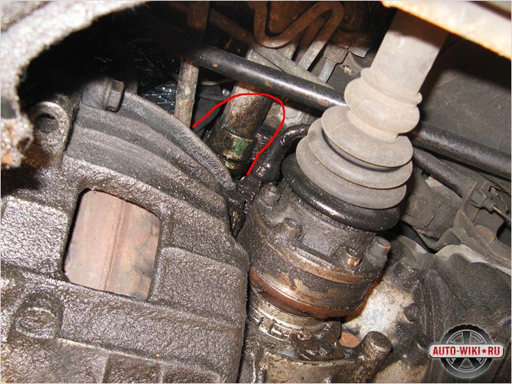
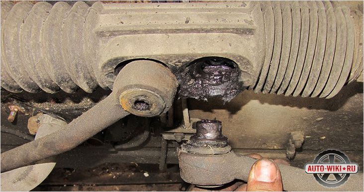
Photo of the steering intermediate shaft:
why such a perversion. It is relatively easy to remove / install.
And then everything is simple.
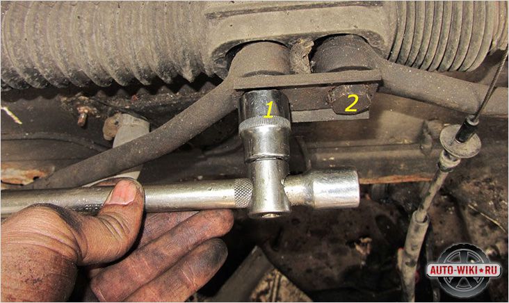
to loosen the nut. You can use a motorcycle wrench (for the exhaust pipe nut).
.No key just doesn't go there. I tried, and if you find a sickle-shaped key of this size, climb there. easier with a chisel. [/ quote]
| Video (click to play). |
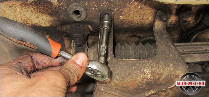
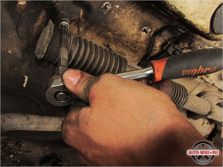
tightened the nut with an ordinary open-end wrench.
when setting it up, it is advisable to remove the left wheel - it's easier this way)
simply. but it takes a little time.
withdrawal for 20-25 minutes. setting 40 minutes.
but then he sat down to himself and under normal conditions you can sort it out. instead of writhing with a chisel and hammer under the car.
I studied the situation closely - I wrote above:
took less than a month ago Tavria myself.
the owner was not greedy, and changed and repaired everything and everyone in her.
he immediately said that the rail was being sorted out recently.
there is a small Chinese Zhiguli steering wheel in the car.
so the rail was so clamped that it was a steering wheel and was not going to return itself at the sharpest turn.
Well, this did not suit me.
and the next day I bought the car I decided to adjust the rail.
And now, having a bunch of all kinds of tools, and the same sickle moto keys, I fucking did that right away.
and could not break this counter nut with a chisel.
in short, he spat and took off the rail.
it can actually be removed in 5 minutes, provided that the bolts are not rotten.
no problem.
and only in a vice, holding the rail, I managed to rip off the lock nut.
then loosened the tightening and tightened the counter nut. but the specialist is not so strong.
installed on the car also in 5 minutes, but was ambushed with a steering shaft.
very strongly pushed the shaft out of the rail into it and could not insert the bolt.
tormented breaking his back on the threshold of the car for probably an hour.
in the end, he spat and decided to remove the rail again and reinstall it, but paying attention to the “steering shaft-rod” moment.
so I think that REIKU IS EASIER TO REMOVE.
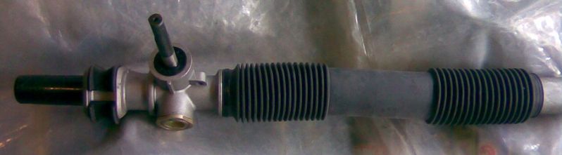
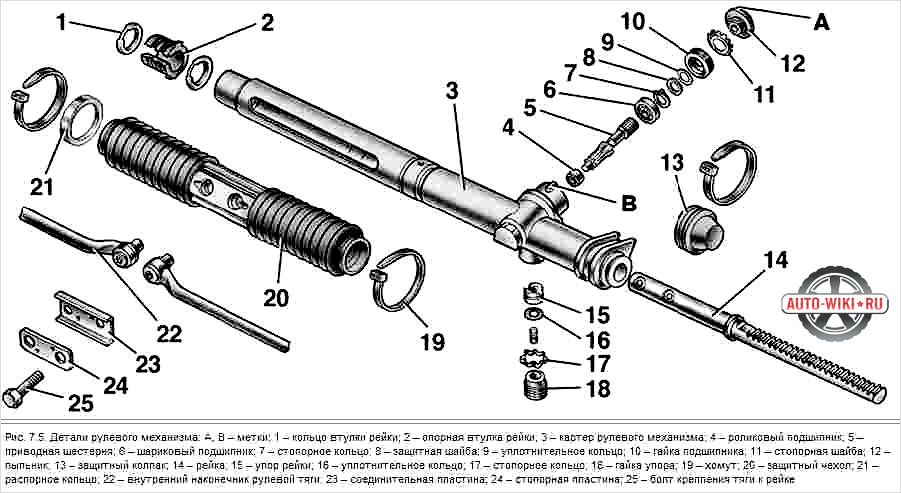
Steering mechanism:
- Left cover.
- Steering rack.
- Clamp.
- Carter.
- Heel pad.
- Inner bearing.
- Outer bearing.
- Spacer sleeve.
- Lid.
- Sealant.
- Gear shaft.
- Adjusting shim.
- Rail stop.
- Spring.
- Lock-nut.
- Crankcase plug.
- Rail bushing.
- Right cover. B. Size for fitting expansion shims. D - cavity for lubrication
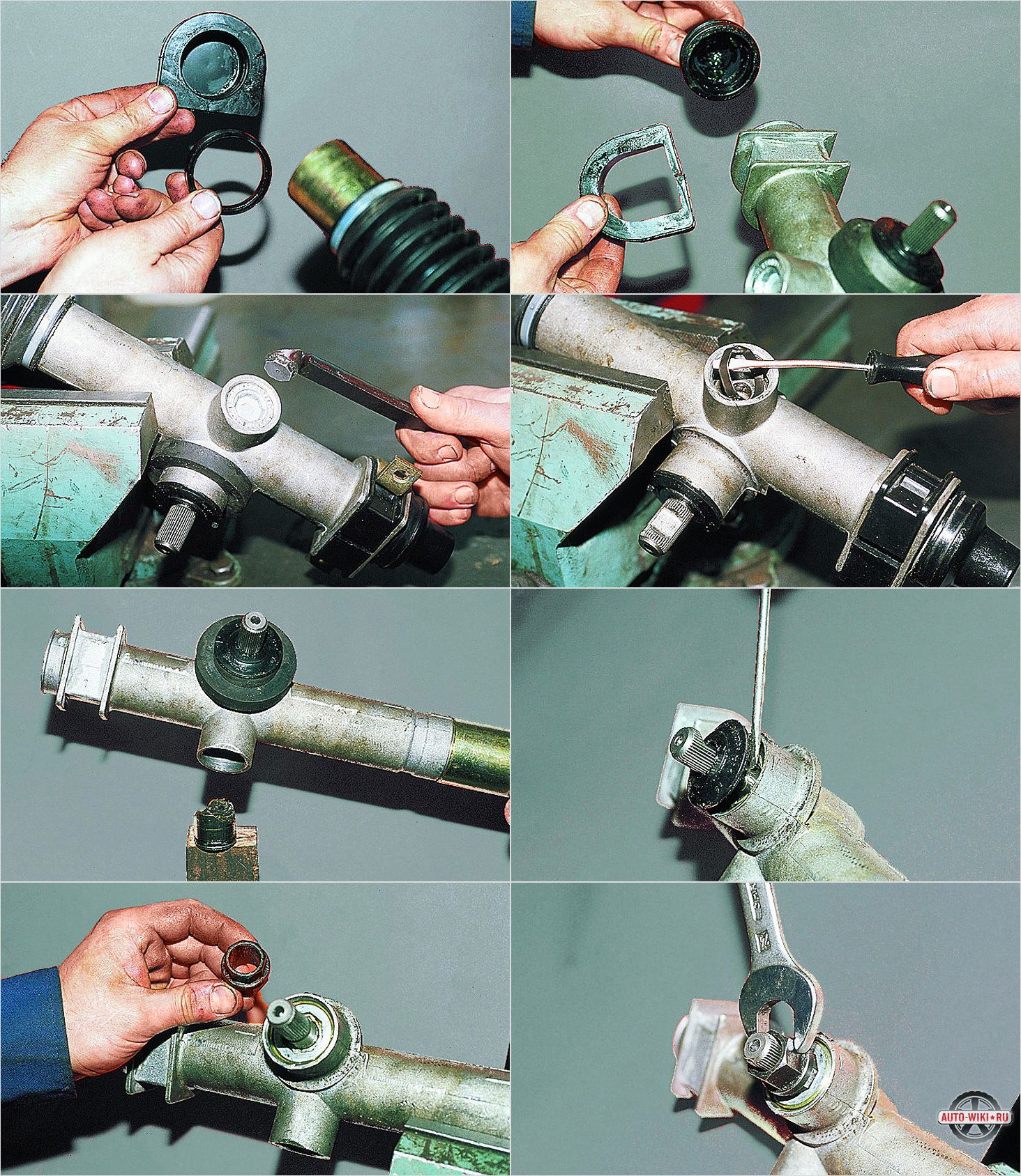
Disassemble the steering gear in the following sequence:
Assemble and adjust the steering gear in reverse order with the following features.
- Pre-lubricate the rack shaft and, after filling the teeth with a grease consisting of 1.5 parts of Fiol-1 grease and one part of engine oil (only 50 g of such grease is needed), insert the rack into the crankcase from the short side.
- Put the covers on the crankcase and secure them securely with clamps.
- Insert the pinion shaft into the crankcase so that it engages the rack, also filling the teeth and bearings with grease.
- After installing the spacer sleeve and fully seating it, measure the protrusion of the sleeve from the crankcase (dimension B in the figure "Steering mechanism"). The thickness of the gaskets is selected for the amount of protrusion. For this purpose, shims with a thickness of 0.1 are provided; 0.15; 0.5 mm.
- After selecting the desired thickness of the gaskets, close the crankcase with a lid and fasten with bolts, tightening them evenly, but not completely. When tightening the bolts, rotate the gear in both directions and check its axial movement. If the turning force of the gear increases when tightening the bolts, add shims between the cover and the crankcase. If there is axial play of the gear, reduce the thickness of the spacers.
- Tighten the cover bolts only after the final adjustment of the gear position. The torque of the gear when correctly adjusted should be 0.02
| Video (click to play). |
0.1 N m (0.002. 0.010 kgf m). The axial play of the gear is not allowed.
To disassemble the shaft support, install the support in a vice, turn the technological part perpendicular to the shaft and remove it from the support (if the technological part was installed when the support was removed from the car).
Remove the shaft, spring, bearing stop and bearing from the support. Then, using a screwdriver or a bit, drive the support sleeve out of the shaft support. Remove dust and dirt from parts and inspect their condition. If there is a noticeable play in the bearing, and the support is deformed, damaged or lost elasticity, replace the parts with new ones.
Assemble the shaft support in the reverse order. Insert the support bush with a screwdriver or a bit into the grooves of the support. Then slide the parts onto the shaft in the sequence shown in the figure "Shaft support assembly" (after lubricating the bearing with grease) and aligning the groove A on the spline part relative to the hole on the support, that is, the hole on the shaft support and the hole for the pin bolt ( on the lower shaft) must be in the same plane, and the groove A on the spindle part must be perpendicular to the hole on the support. Then, lightly compressing the spring with the shaft, insert the technological part into the hole in the support and shaft perpendicular to the shaft. Rotate the process piece 90 ° to align with the shaft. In this case, the spring will be compressed and a size of 128 mm will be provided between the end of the support and the shaft.
When installing the support assembly with the upper and lower shafts (the position of the rack in the steering gear must correspond to the rectilinear movement of the car), insert the spline part of the lower shaft into the steering gear shaft so that the spline coupling pinch bolt is located with the head on the bottom. Secure the support in this position with four bolts to the pedal bracket. Tighten the clamp bolt on the lower shaft and remove the process piece from the support.
The main function of the steering rack (reducer) in the car device is to organize the rotation of the car. The steering rack is present in cars with power steering, as well as in those cars in which there is no power steering. It connects the steering wheel to the wheels, and therefore its role is very important for safe movement in the car. The diagnosis of this mechanism must be approached with the utmost responsibility, as well as repairs.
All cars are subject to rapid wear of steering parts, regardless of price and status, because it is these parts that take a hit at any turn, hitting an obstacle, hitting the wheels on bumps on the road.
To determine if your vehicle's steering needs repairs, look for the following signs of a malfunctioning mechanism:
- there is clearly a knock on the steering rack, which is felt through the steering wheel of a car;
- increased effort required to rotate the steering wheel;
- there were extraneous sounds and noise in the power steering pump;
- there was a backlash in the steering rack, which is felt when the steering wheel rotates;
- power steering oil began to leak from the steering rack.
If any of these signs appear, do not delay repairing the steering rack. Untimely repair of steering parts can lead to loss of maintainability of the mechanism.
So, you have a steering rack leaking. What to do, how to make repairs and adjust the steering performance?
First of all, it is worth noting that it is actually very difficult to repair this unit, and it is worth starting the procedure only if you have all the necessary equipment at hand, as well as experience and knowledge in the field of car construction.
The steering rack mechanism consists of the following parts:
- toothed shaft;
- steering rack support sleeve;
- spool mechanism.
Repairing a steering rack usually consists of several stages:
- Dismantling, disassembling the steering rack and cleaning the accumulation of all its parts.
- Replacement of damaged parts of the mechanism with new parts.
- Diagnostics of the toothed shaft of the steering rack.
Before starting repair work, you should get a special repair kit, which includes new parts for the steering rack (oil seals, steering rack bushing, ring seals, and others).
How to remove the steering rack.
- Drive the car into a hole or raise it with jacks.
- Remove the engine protection (if you have one).
- Remove the steering rack heat shield.
- Unscrew the fasteners on the steering rack.
- Remove the rail from the mountings and pull it out of the interior of the car.
It is worth noting that it will be better for you to remove the steering rack along with the steering rods, because the new anthers will be much more convenient to pull on the special protrusions on the steering rods. This will help you to fit perfectly sealed anthers.
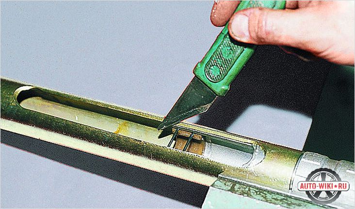
- Unscrew the rack from the steering rods using a special flat-head screwdriver.
- Unscrew the bottom plastic gear shaft plug.
- Unscrew the lock nut.
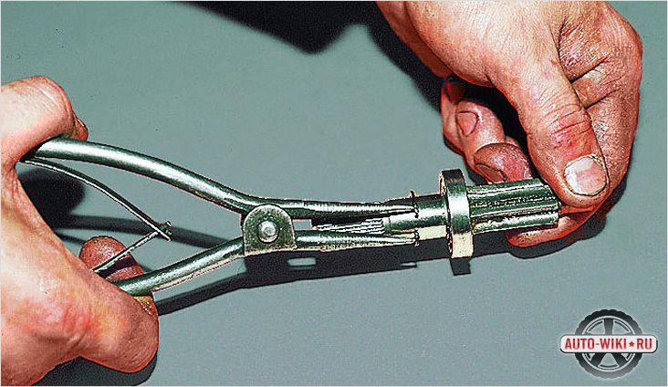
- Remove the retaining ring and gently knock the shaft out of its place.
- Pull out the lower oil seal.
- Tap out the locking pin that is blocking the upper oil seal.
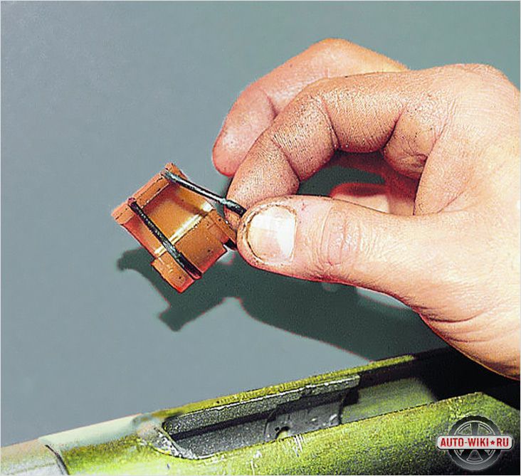
- Unscrew the retaining plug and pull the retaining ring out of the wire that will show up as you turn it.
- Pull the steering rack out through the right side and remove the oil seal and plastic bushing from the rack.
- Remove the oil seal and plug, pull out the spring and pressure mechanism.
Next, wash all parts from oil and dirt deposits and carefully inspect all parts for mechanical damage due to wear. All damaged parts must be replaced without fail. If the surface of the steering rack and the gears of the toothed shaft have significant damage, then most likely it will be necessary to replace the entire mechanism as a whole (how to replace the steering rack with a VAZ 2109, read in our material).
- Carefully install the inner oil seal in its place, having previously lubricated it with special grease (you need to put it through the right side with the spring down).
- Place the rail into the housing.
- Slide the plastic sleeve over the right gland, lubricate all parts with grease, and push the gland back into place by pushing something.
- Install the plug and secure it with the retaining wire.
- Slide the lower oil seal onto the toothed shaft.
- Place the steering rack in the middle position.
- Insert the toothed shaft into the seat after lubricating the seals with grease.
- Gently push the upper oil seal into place, using a hammer to push it into place. Install the retaining ring.
- Install the bottom lock nut, bearing, plug.
- Install the hold-down mechanism, spring and plug. Tighten tight.
Then install the rail on the car in reverse order. Be sure to do “camber-convergence” after the procedure for repairing or replacing parts.
Do-it-yourself steering rack repair without and with power steering has a lot in common, the differences are minor: different bushings and the composition of the lubricant.
If any of these signs appear, do not delay repairing the steering rack. Untimely repair of steering parts can lead to loss of maintainability of the mechanism.
Is a child growing up in your family? Naturally, the kid enjoys decorating the flowers on the wallpaper, tearing them off the wall. You have to periodically wash the wall covering, glue the wallpaper. When the child grows up, you can repair the steering rack with your own hands, Slavut, which will return the apartment to its original appearance. Modern materials make it possible to bring to life the most interesting solutions, to completely renovate the home.
Life goes by rapidly, one day is similar to another. Do you want variety, a change of scenery? The continuous work schedule provides for constant employment in the service, you have to be at home only in the evenings. An excellent solution would be the device and repair of piston compressors of the apartment, which allows you to bring a new note of pleasure into your life. You can contact a specialized company that offers a turnkey service.
How to renovate your apartment or house if there is no time at all? At the moment, the opportunity to contact professionals who are ready to completely revitalize your premises is quite popular. Qualified designers develop projects, companies offer the opportunity to perform body repairs in Ufa on a turnkey basis. You do not have to buy materials yourself, hire workers, control the process.