In detail: do-it-yourself defender subwoofer repair from a real master for my.housecope.com.
DIY subwoofer repair - one of the most common breakdowns occurs in the amplifier, which is built into the subwoofer. Many inconveniences are caused by network distortions in the sound, it is the frequency of 50 Hz that brings the most low-frequency interference into the sound path. Therefore, most often you have to deal with this frequency as a hindrance.
Penetrating into the acoustic circuit, this noise creates an unwanted low-frequency hum in the dynamic radiators. One of the effective options for reducing such a defect is to install large capacitors in the supply voltage circuit to smooth out the rectified voltage. As a rule, in circuits assembled on transistors or microcircuits, the culprit is an electrolytic capacitor in the filter circuit that has become unusable. Therefore, noise distortions appear in the speakers.
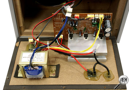
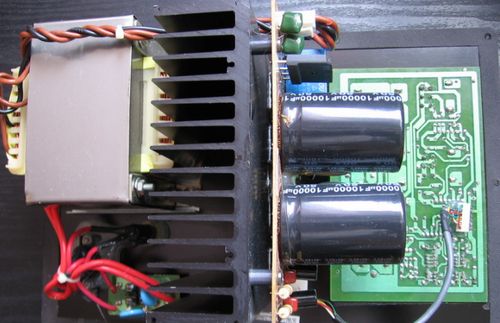
DIY active subwoofer repair and in the process of searching for the cause, we dismantle the heat sink and the following picture appears before us: one of the capacitors has become "pregnant" (it can be seen in the picture). In addition, the contact pad was torn out on the textolite printed circuit board.
For a high-quality amplifier repair, it is necessary to change both capacities at once. Since the second condenser, too, could have lost some of its capacity, and this pair must be identical. Therefore, we immediately change the pair, so it will be more reliable and will last longer. In addition, as it turned out, the outer shell of the capacitor burst from internal pressure, and the electrolyte leaked out and stained the board.
We solder the problem capacities, and instead of them we install new capacitors, preferably from well-known companies.
| Video (click to play). |
Next, you need to clean the printed circuit board with alcohol from the electrolyte that has got on it, put the containers in place, not forgetting to observe the polarity and solder.
In my case, I had to format the pins of the new capacitors a little, since the holes in the board were slightly wider in the centers. After molding, they fit perfectly into place. But still, for greater reliability, it is better to treat the base of the tanks with thermal glue or epoxy glue to resist vibration inside the subwoofer.
What should be done when the LEDs for visual control over the operation of the device indicate that everything is normal, but one channel still does not work. This problem may also indicate a malfunction in the amplifier. However, you should first check visually and by ringing the signal path going from the sound source to the subwoofer.
In addition to the above described repair of the printed circuit board to replace swollen capacitors, you need to check the output transistors or integrated circuits. It is also very likely that the fault is in the power supply, which does not supply the circuit with the required supply voltage. In fact, any radio equipment should always be repaired by checking the power supply, that is, by measuring all outgoing voltages.
How to repair a car subwoofer, and indeed a subwoofer in general, is one of the frequently asked questions, due to their widespread use in audio equipment.
There are three options: buy a new one, take it to a service for repairs, or repair it yourself. To repair subwoofers yourself, you need to understand a little about electronics, as well as be able to use a soldering iron and a tester.
Subwoofer 5, 1 consists of a speaker, speaker, and amplifier, as well as a power supply:
- The loudspeaker usually fails only from mechanical damage
- Failure of the dynamic head is caused by hitting its coil of an audio frequency with a power for which the head is not designed, or a constant voltage, which causes the coil to burn out
- When listening to a speaker with amplification at maximum power, you will encounter the problem of wear (rupture) of the speaker cone
- If the speaker breaks down, it must be replaced, since rewinding the coil or repairing the subwoofer diffuser is a delicate painstaking work and it is very difficult to do it efficiently so that the sound does not deteriorate.
First you need to find out which of the elements of the subwoofer failed:
If you firmly decided that rewinding the subwoofer speaker is not a problem for you, then prepare the following materials and tools:
- Shellac (or epoxy) for coating the subwoofer winding
- Solvent
- Rubber glue
- Screwdriver
- Soldering iron
- Micrometer
- Screwdriver
Not everything is as simple as it seems, self-repair of an auto subwoofer, the work is painstaking:
- First, we need to carefully disassemble and remove the subwoofer head, we should act slowly, sudden hand movements are unacceptable, otherwise you can damage the coil sleeve
- In addition, it is necessary to observe cleanliness in the process of work so that dust does not get into the magnetic system, and even more so metal shavings
- Otherwise, after spending a lot of time and effort, instead of a working subwoofer, we will get a pile of clanking rubbish.
- When we got to the sleeve itself, you should carefully unwind the old wire, while counting the number of turns in the layer and the total number in the coil
- Here, the more accurately you count, the better the quality of the repair is as a result.
- Then it is imperative to measure the diameter of the wire.
- A micrometer is needed for this purpose.
- You can, of course, measure it with a caliper, but the measurement accuracy is lower, if there are no such instruments, you can cheat
- Wrap a wire on a screwdriver or a nail, very tightly so that turn to turn, and so 10 - 30 turns, measure the length of the winding with a ruler
- Then you need to divide this length by the number of wrapped turns, and you will get the approximate diameter of the required wire (the ruler error is large)
Now you need to prepare the subwoofer diffuser for rewinding:
- Using a mandrel suitable in diameter, fix its sleeve in a screwdriver
- It is necessary to very accurately fit the mandrel and the sleeve, so as not to deform during the process of rewinding.
- We smear the surface of the sleeve with epoxy or varnish
- Then you will need to clean the wire of the required diameter
- We pass the wire through a cloth soaked in solvent
- After that, we lubricate with epoxy or shellac
- Of course, after this, the instruction prescribes that the coating must dry out.
We have the wire and sleeve ready, go to rewind:
- We immediately solder the beginning of a new winding to the second, if we go along the winding of the wire, the output (thus we exclude unnecessary crossing of the wires, this has a positive effect on the service life of the repaired speaker) and start winding, photo below
- At the same time, it is important to fix the tightness and do not forget to count the turns, because the more accurately we wind, the closer the speaker characteristics will be to the factory characteristics.
- After each layer, it is better to go through the winding with varnish, after laying the winding, solder the second contact, cut off the wire
- Coat the entire coil with varnish again
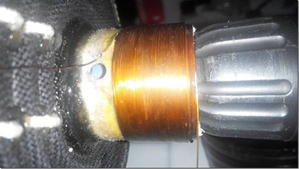
The first layer of our winding, put on a screwdriver
- After the end of winding the coil, you will need to leave it for a day to completely dry
- And if you used shellac, then the coil must be heated to 80-120 degrees (for example, in the oven)
- Shellac will not otherwise solidify
- Here is the main disadvantage when using shellac.
- But when it dries up, a certain amount of elasticity remains, which completely excludes damage to the winding from drying out of the impregnation or during its thermal expansion
- After drying, it remains to attach the diffuser to the speaker, and
- repair of car subwoofers is considered successful if everything works
To prevent the coil from rubbing against the magnetic system, we need to set a uniform circular gap:
- For this purpose, paper cut into strips is suitable.
- We insert it in a circle (where possible) between the body and the coil, thereby obtaining a uniform gap
- Check for jamming and snagging by moving the diffuser gently up and down with your hand.
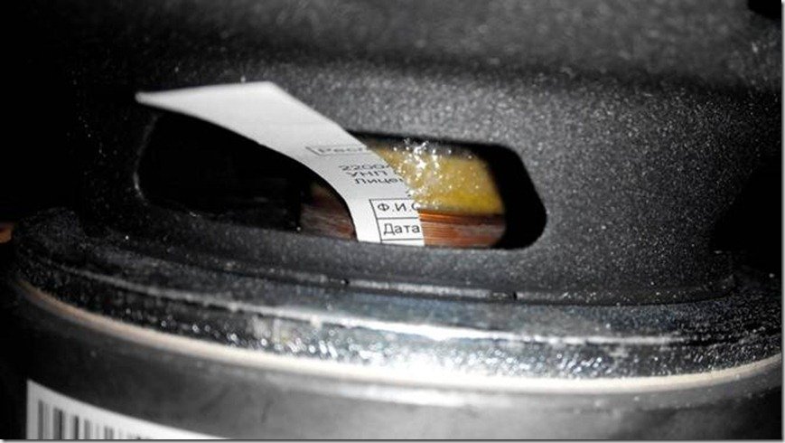
We insert pieces of paper between the coil and the body
- Then we glue the suspension of our speaker and carefully insert it into place
- Give the details time to dry
- Then you can pull out the centering papers
- Check again for sticking
- When everything is in order, put a layer of glue
- We dry and put the finished subwoofer in the car for checking
- Do not forget to lower the volume by half.
- Subwoofer rewind complete
The device is almost the same, except that the dimensions are larger, microcircuits, or capacitors can be in a different order:
- Let's take a closer look at the voltage converter, power supply and amplifier.
- The ceratec subwoofer amplifier is usually two-channel, but two channels are connected to one single dynamic head
- Moreover, each channel in the amplifier amplifies a different sound frequency, low and medium, as a rule
- In addition, modern amplifiers, almost all, operate on one microcircuit from the TDA series.
- To get more power at the amplifier output, twelve volts from the on-board network of the car is not enough, for powerful microcircuits the supply voltage is from 40 volts
- Therefore, in the b w subwoofer circuit there is a built-in high-frequency converter that converts the 12 volt voltage into the necessary for normal operation of the amplifier
- In the figure, we have divided the entire scheme into three main blocks. A1 - equalizer control, it breaks down extremely rarely, you need to try to break it, we will not devote time to it, it changes entirely
- A2 is a voltage converter, and A3 is a power amplifier.Let's dwell on A2 and A3 in more detail
Slightly enlarged diagram
- The voltage, through the filter, comes to the capacitor C1, from there it is fed to the transistor switches VT1 and VT2
- Transistor keys are controlled by a high frequency signal generated by the DD1 microcircuit
- The amplified signal from the transistors VT1-VT2 comes to the transformer T1, where the voltage turns from 12V to 40 Volts
- Moreover, the secondary winding of the transformer consists of two windings, a rectifier consisting of two diodes is used for rectification
- To unload these diodes, two more diodes are installed in parallel.
- Each of the DD2 and DD3 microcircuits is powered only by its own diodes
- To smooth out high-frequency pulses, capacitors are installed, C2 and C3 are marked.
- Converter A2 ends at this point, then comes the power amplifier A3
- Modern amplifiers consist of a single microcircuit
- At its input, in order to obtain normal output parameters, a signal of a certain magnitude must be present
- The designers of this subwoofer decided that not every car radio would have enough power, or rather the strength of the output signal from the primary amplifier, in order to obtain the nominal output parameters.
- Therefore, a transistor was added to amplify the signal before the input of the microcircuit, on the DD2 and DD3 circuit
- Here is a list of the main radio components that fail most often.
- It happens that for the replacement of one capacitor the price in the workshop will be considerable, but the work is penny
- Therefore, it is better to check the entire scheme yourself before paying without looking.
Additionally, I recommend that you study the repair video.
Good day!
There are two columns 10MAS-1M:
Rated input power 10 W, maximum 15 W.
The nominal input electrical resistance is 8 ohms.
and active subwoofer Defender Blaze 50:
Power 20 W
Resistance 8 Ohm
Is it possible and how to connect? otherwise they don't play something (
I thought you had a technical background. And judging by your last questions, the available knowledge may not be enough. How about flipping through some popular radio engineering book?
I can, of course, describe everything step by step, but you can't foresee everything. Some points are taken for granted (but not for you) and I can miss them.
For example, I recommended that you take measurements on the problem microcircuit (in the channel where there is no sound), and you, as I understand it, do not even know how to calculate it. But this is a very simple task. You can, for example, ring the “hot” output of the socket going to the problem column with the 4th leg of the microcircuit with an ohmmeter. You can also find this connection visually.
It turns out that I must start by explaining how to use the measuring device, then talk about the preferred shape of the probes and safety measures so that after these measurements something does not burn out. You need at least some basic knowledge and minimal experience.
Do not think that I refuse to help. It's just that we also have our own Hippocratic oath: "Do not make it worse than it was."

The common wire, the one marked with the “housing” icon, is located between the capacitors C1 and C2, and is also connected to the “cold” wire going to the load (speaker).
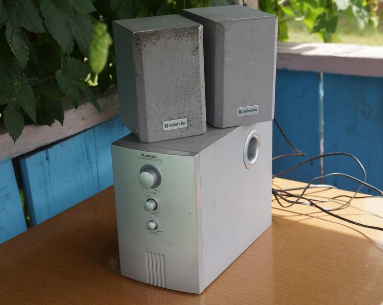
Old Defender Blaze 20 speakers fell into my hands. Their sound is certainly not for serious listening to music, but I needed them and not for that. I used them this summer for background music for gardening work. I live in a village, from spring to autumn you are more often on the street than in the house. And not only for work, sit in the gazebo, cook a barbecue, chat with friends. Taking the acoustics out of the house for this period is not an option, so I adapted these speakers.
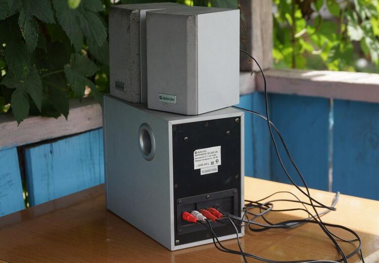
The power of this 2.1 system is not great: 25W. But this was enough, although at maximum volume the sound began to rattle, crackle.
Their subwoofer is built according to the scheme Band pass, based on 4 ”speaker. The idea to remake it arose after I found a 5 ”speaker from the speakers from the music center. As a type of acoustic design, I chose a case with a bass reflex, as it is more affordable to manufacture.
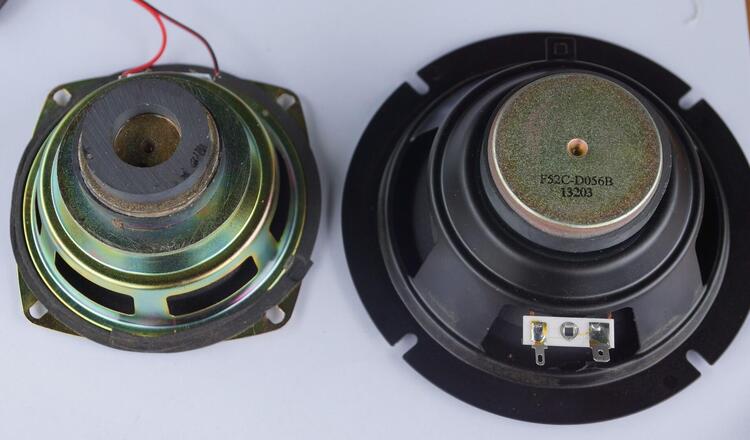
It is worth considering that I am just an amateur, and this is my first experiment in making a subwoofer. This topic interested me very much, so I decided to start with a simple improvement. So to speak, homemade syndrome haunted. As far as I know, not only to me, but also to many members of the club of experts: someone is modernizing the case, doing modding, others are overclocking out of sports interest, and a lot of other interesting things.
I did not calculate the case, I took the size of the native speaker as a basis, in which this speaker stood.
The body should have turned out to be about 11 liters. Having estimated the dimensions of the existing phase inverter pipe, I received an estimated resonant frequency of 40Hz.
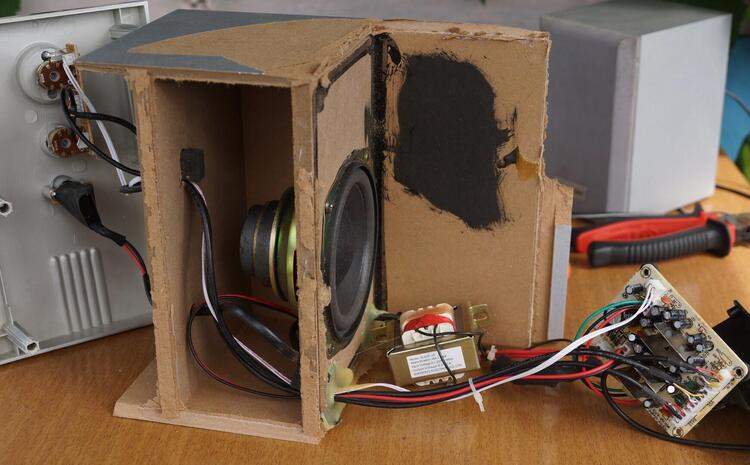
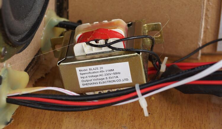

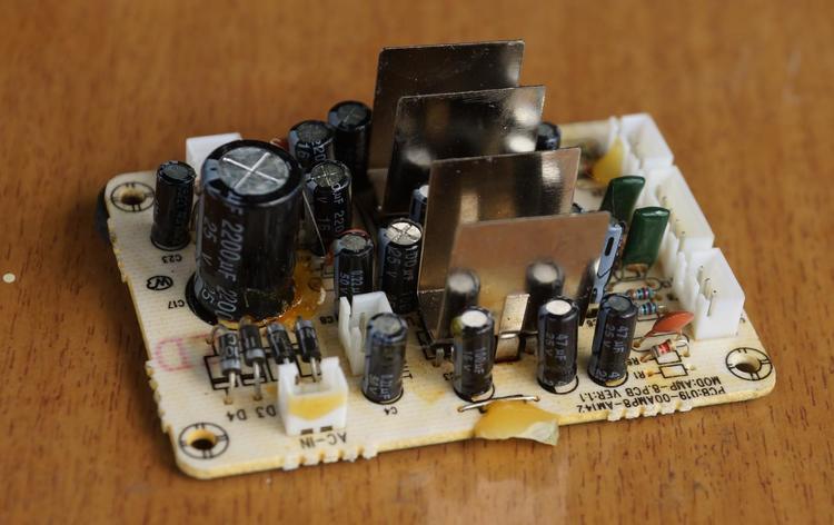

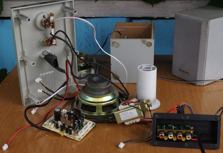

Disassembled, or rather broke the subwoofer case. It was glued from 5 mm fiberboard, more often referred to as hardboard. The amplifier is assembled on two unknown microcircuits, to which tin radiators are glued and additionally soldered into the board. 8.5V / 1A transformer.
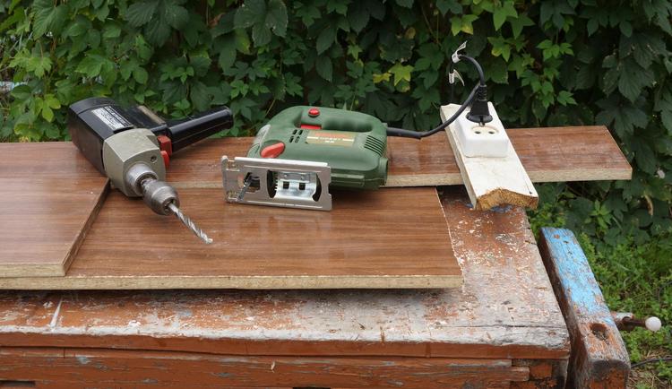
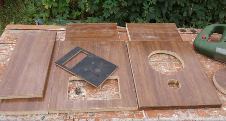


First of all, I lined and sawed 20 mm chipboard, sawed out all the necessary holes with a jigsaw. The dimensions of the case are 30x25x15 cm.
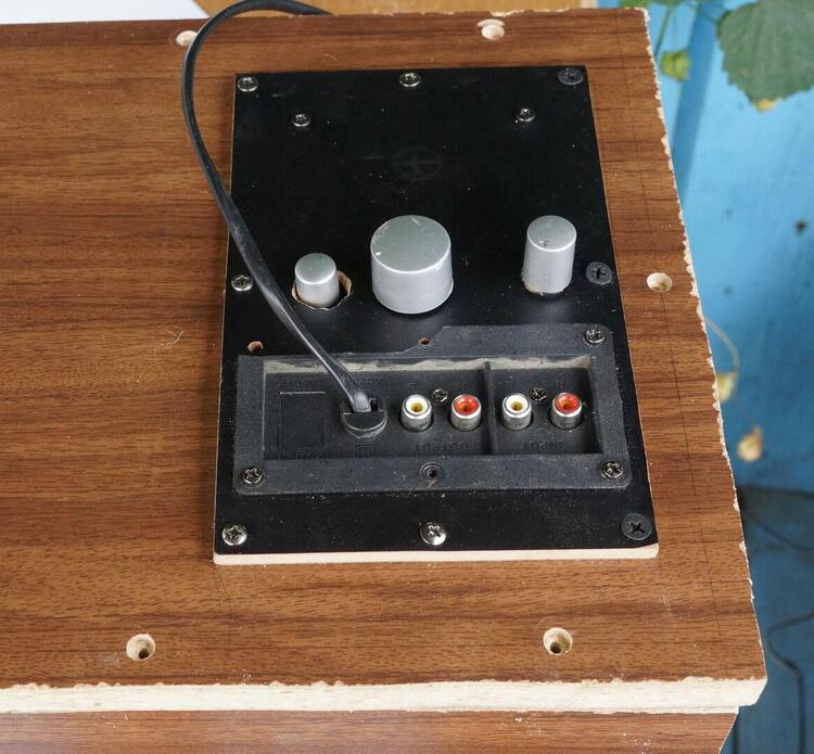
On the back wall I attached a separate removable bracket with stereo input connectors and speaker outputs. In the same bar, I built in a tone block, on which there were volume and low frequency controls, and here I also attached a power button.
I had to tinker with the hole for the power button, gluing it from the inside to avoid air whistling through the gap. I screwed an amplifier circuit and a transformer onto the back cover.
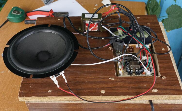
The assembly began from the front panel and side walls. I glued the “moment” with liquid nails and fastened it with self-tapping screws. Then I pasted over the inner walls with sound-absorbing material. After checking the system's performance, I screwed the back cover, pre-lubricated with glue.
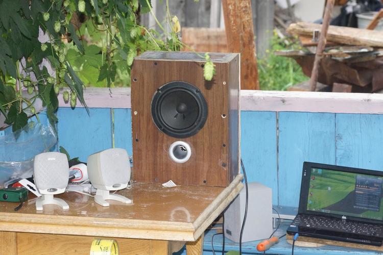
Glued the phase inverter pipe. I cut out a rubber gasket under the speaker to ensure a snug fit to the hole.
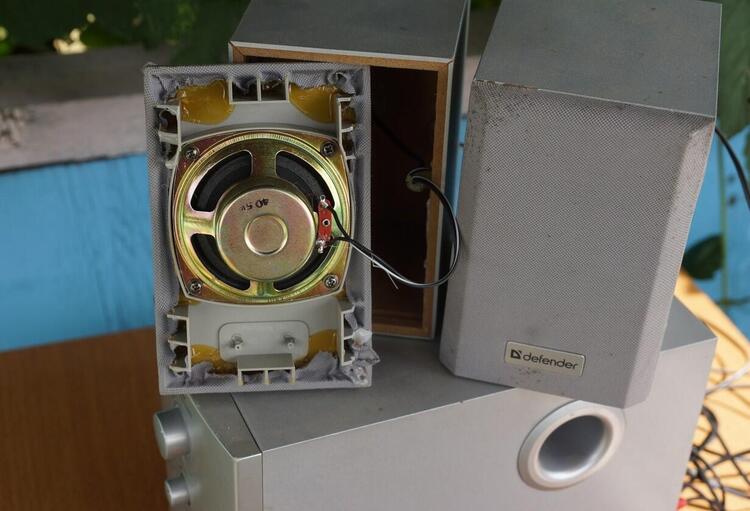
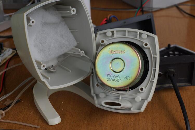

As satellites, I first connected the native Defender speakers, but then, for the experiment, I connected the Edifier speakers.With the same characteristics, they sound better, have vibration damping material and a bass reflex.
The first activation of the system left a double feeling. Well, first of all, the volume of the buffer has increased. If the old one just hummed, mumbled and resonated, then this one is already singing. But with the maximum increase in the level of low frequencies, sound distortion, wheezing appears.
In general, the subwoofer complements the sound of the satellites well, adding low frequencies to the overall sound picture. And the old one only spoiled the sound with its resonant rumble, because of this I only increased the bass volume on it by a quarter. And all the sound was only due to the speakers.
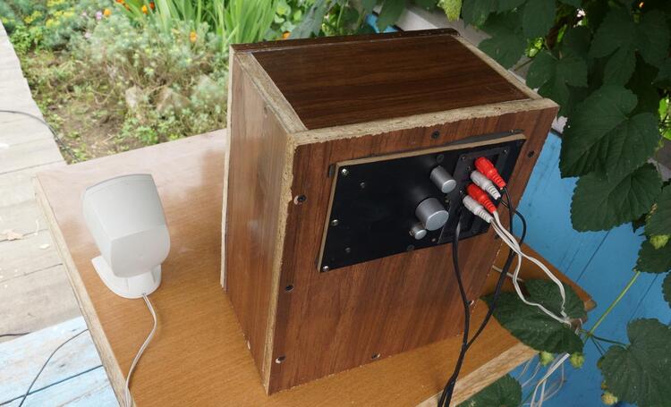
The result is quite decent acoustics, which can be heard in the yard, on the veranda of the house, in the far corner of the garden, and even in the yard of neighbors.
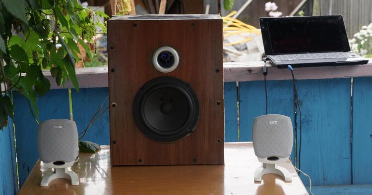
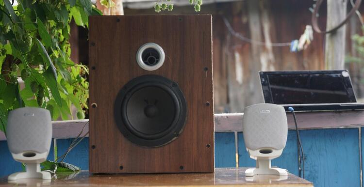

Yes, as you probably already understood, the revision did not solve all the problems of the speaker, it is impossible to solve them only at the expense of the case. The quality of the speakers themselves, the amplifier, plays a very important role. But such a major upgrade will already require financial costs.
But, as they say: "The main thing is not victory ...",
I liked the process itself and the result, when you do something with your own hands, you enjoy it. I think to continue experiments in this direction. Perhaps this will be the finalization of the satellites and even the electronic part. And possibly passive speakers based on car acoustics.
To assess the resulting result, I uploaded a video taken on a Sony A65. Shooting from a distance of 2 meters.
At the end of the recording, a pop composition sounds quite good.
Some moments of the work did not get into the frame, I was carried away and forgot to take pictures, for example, there are no insides of the case after pasting with damping material.
I would be glad to any advice in the comments about the improvements, as well as if someone shares their experience in this area.
Many motorists want to save on little things, so they are eager to learn how to repair a subwoofer with their own hands. At the same time, having little professional knowledge in this area, it is quite possible to make home repairs of the subwoofer with your own hands.
However, some repair actions for the Sven car subwoofer unit should be performed exclusively in a car center. By the way, you don't have to carry the subwoofer if the amplifier, suspension or one of the speakers is out of order.
The question of how to repair a subwoofer often arises among the owners of not only automobile, but also the rest of the audio equipment, since no one wants to give up excellent acoustics.
You can carry out high-quality repair of car subwoofers by talking with professionals or by watching the corresponding video on Internet resources. At the same time, repairing a subwoofer is available to everyone who has a little free time, perseverance, and also owns a soldering iron or a tester.
It is worth noting that you can only repair a subwoofer after understanding its device and identifying the problem.
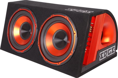
For example, in an ordinary home or car subwoofer, the following may fail:
The reasons for the failure of the amplifier or speakers, as well as its other parts, include:
- violation of heat exchange;
- accumulation of dust or dirt;
- lack of voltage at the output from the power unit;
- swollen capacitors;
- lack of current on the supply element of the unit;
- burnt out coil of the transformer.

Moreover, all these problems are solved simply and easily, because:
- the reel is rewindable;
- dust and dirt can be really cleaned;
- swollen capacitors are subject to replacement, which should be unsoldered and replaced with those purchased in the store;
- the diffuser is easy to glue with adhesive tape, having previously coated it with rubber-based glue.
If a person does not have the slightest experience in this repair or does not know how to handle a soldering iron, then he simply must turn to professionals, and certainly, one cannot rewind the transformer coil, since it can be irrevocably ruined.
The fact is that repairing a subwoofer amplifier is not difficult, but you will not be able to figure it out without delving into the main features.
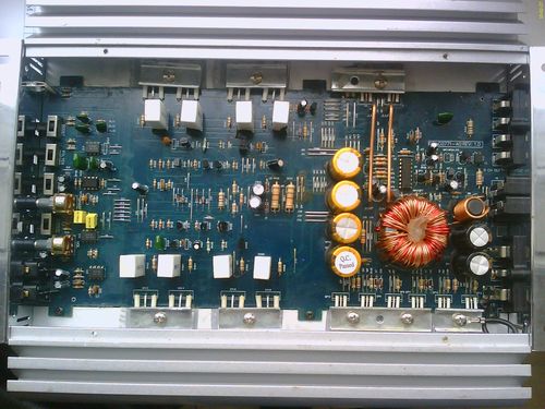
When starting to repair a car subwoofer, you should:
- remove the amplifier from the vehicle;
- unscrew the metal plates;
- consider them more closely, since the problem may be in the burned or melted amplifier plates.
How to repair a Sven subwoofer if the amplifier plates are out of order? It is worth going to the car market and purchasing similar or more powerful records and a tube of thermal paste.
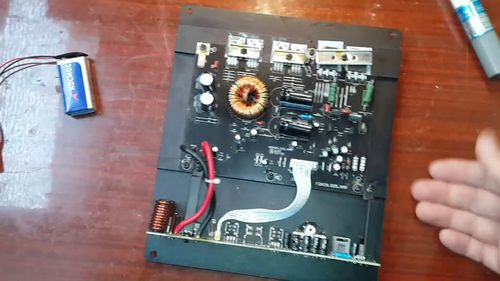
After that, the following actions are performed:
- wipe all parts of the subwoofer amplifier with alcohol;
- solder to the desired place on the plate;
- smear everything with thermal paste;
- collect the entire structure back;
- install on the car and check after a while.
In order to make a high-quality repair of the subwoofer speaker, you need to decide what exactly to fail in it. To practice repairing the speaker, you should take old speakers that are out of order, for example, BW PV1, Sven, Infinity.
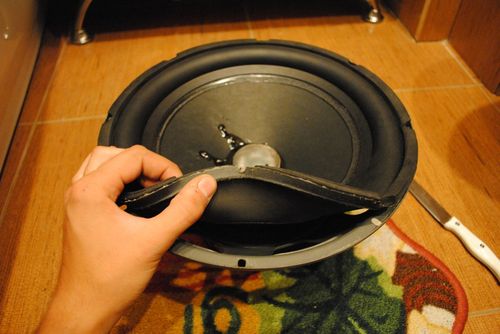
Then you should disassemble the speaker and follow several consecutive steps, including:
- soften the glue that binds almost all parts of the speakers;
- this can be done with a syringe with a needle and a high-quality solvent;
- separate all parts from each other, not forgetting about the dust-type cap;
- disconnect the diffuser suspension from the basket of the upper speaker;
- separate the centering washer of the lower suspension by saturating it with solvent;
- wind the coil on a blank, and in two layers, using a thin wire.
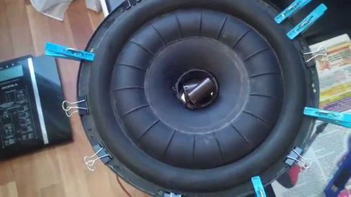
By the way, a cylinder made of aluminum can serve as a frame for the coil. In this case, you can rewind this coil with wires of increased cross-section, however, its parameters should be close to the previous one. That is, if a wire with a cross-section of 0.45 millimeters was used for a burned-out coil, then an analog of 0.40 millimeters can be successfully used.
High-quality repair of the Sven subwoofer is carried out only after familiarization with its technical parameters, which are stated in the instructions, in order to determine the possibility of switching the phase, weight, diameter, output power, voltage, frequency range.
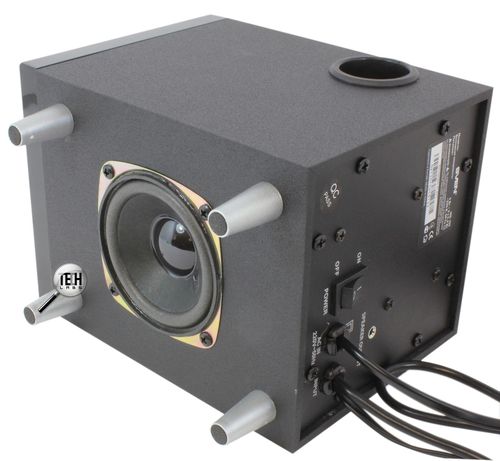
At the same time, before repairing a home or car Sven subwoofer with your own hands, you should understand that it will be much more difficult to do this than fixing a breakdown in a BW PV1 or Infinity.
For example, to repair the amplifier of a car subwoofer, you will have to unscrew at least a dozen self-tapping screws in order to get close to the electronics and get a solid block.
Most often, microcircuits and transistors fail on this model, including a power amplifier of the TDA2030 type, since it does not tolerate short circuits, increased load, overheating or adhesion of dirt.
Is your TV, radio, mobile phone or kettle broken? And you want to create a new topic about this in this forum?
First of all, think about this: imagine that your father / son / brother has an appendicitis pain and you know from the symptoms that it is just appendicitis, but there is no experience of cutting it out, as well as the tool. And you turn on your computer, access the Internet on a medical site with the question: "Help to cut out appendicitis." Do you understand the absurdity of the whole situation? Even if they answer you, it is worth considering factors such as the patient's diabetes, allergies to anesthesia and other medical nuances. I think no one does this in real life and will risk trusting the life of their loved ones with advice from the Internet.
The same is in the repair of radio equipment, although of course these are all the material benefits of modern civilization and in case of unsuccessful repairs, you can always buy a new LCD TV, cell phone, iPAD or computer.And for the repair of such equipment, at least it is necessary to have the appropriate measuring (oscilloscope, multimeter, generator, etc.) and soldering equipment (hairdryer, SMD-hot tweezers, etc.), a schematic diagram, not to mention the necessary knowledge and repair experience.
Let's consider the situation if you are a beginner / advanced radio amateur who solders all sorts of electronic gizmos and has some of the necessary tools. You create an appropriate thread on the repair forum with a short description of “patient symptoms”, ie. for example “Samsung LE40R81B TV does not turn on”. So what? Yes, there can be a lot of reasons for not switching on - from malfunctions in the power system, problems with the processor or flashing firmware in the EEPROM memory.
More advanced users can find the blackened element on the board and attach a photo to the post. However, keep in mind that you replace this radio element with the same one - it is not a fact that your equipment will work. As a rule, something caused the combustion of this element and it could “pull” a couple of other elements along with it, not to mention the fact that it is quite difficult for a non-professional to find a burned-out m / s. Plus, in modern equipment, SMD radio elements are almost universally used, soldering which with an ESPN-40 soldering iron or a Chinese 60-Watt soldering iron you risk overheating the board, peeling tracks, etc. The subsequent restoration of which will be very, very problematic.
The purpose of this post is not any PR of repair shops, but I want to convey to you that sometimes self-repair can be more expensive than taking it to a professional workshop. Although, of course, this is your money and what is better or more risky is up to you.
If you nevertheless decide that you are able to independently repair the radio equipment, then when creating a post, be sure to indicate the full name of the device, modification, year of manufacture, country of origin and other detailed information. If there is a diagram, then attach it to the post or give a link to the source. Write down how long the symptoms have been manifesting, whether there were surges in the supply voltage network, whether there was a repair before that, what was done, what was checked, voltage measurements, oscillograms, etc. From a photo of a motherboard, as a rule, there is little sense, from a photo of a motherboard taken on a mobile phone there is no sense at all. Telepaths live in other forums.
Before creating a post, be sure to use the search on the forum and on the Internet. Read the relevant topics in the subsections, perhaps your problem is typical and has already been discussed. Be sure to read the article Repair strategy
The format of your post should be as follows:
Topics with the title “Help fix the Sony TV” with the content “broken” and a couple of blurred photos of the unscrewed back cover, taken with the 7th iPhone, at night, with a resolution of 8000x6000 pixels are immediately deleted. The more information about the breakdown you put in a post, the more chances you will get a competent answer. Understand that the forum is a system of gratuitous mutual assistance in solving problems and if you are dismissive of writing your post and do not follow the above tips, then the answers to it will be appropriate, if anyone wants to answer at all. Also note that no one should answer instantly or within a day, say, no need to write after 2 hours “That no one can help”, etc. In this case, the topic will be deleted immediately.
You should make every effort to find a breakdown on your own before you get stuck and decide to go to the forum. If you outline the whole process of finding a breakdown in your topic, then the chance of getting help from a highly qualified specialist will be very great.
If you decide to take your broken equipment to the nearest workshop, but do not know where, then perhaps our online cartographic service will help you: workshops on the map (on the left, press all buttons except “Workshops”). You can leave and view user reviews for workshops.
For repairmen and workshops: you can add your services to the map. Find your object on the map from the satellite and click on it with the left mouse button.In the field “Object type:” do not forget to change to “Equipment repair”. Adding is absolutely free! All objects are checked and moderated. A discussion of the service is here.
Hello. Broken Chinese audio system 2.1 Defender Blaze 50.
Subwoofer with amplifier in one box and two speakers.
Breakdown symptoms are as follows: If both channels are connected to the output, then only the sub is working, while it emits a growing hum.
If you connect one speaker only to the right channel, then only it works, the sub is silent.
If you connect only one to the left channel, the sub makes a growing hum, the speaker is silent.
An autopsy showed that the amplifier is assembled on three TDA2030s. Visually, all components are intact, electrolytes are not swollen.
I found out that when the left channel is connected, the diode bridge heats up, when the right is connected, this does not happen.
I hope you'll give me a hand .
I am attaching a photo of the amplifier, unfortunately taken on the phone, so I will answer all questions about the components.
Thanks in advance.
JLCPCB, 10 PP prototypes for only $ 2 and 2 days delivery!
Good day, dear pikabushniki! This post will tell you how to fix a subwoofer if, for no reason at all, it starts to buzz.
Our dear pikabushnik turned to me with a request “The bufik buzzed, can you fix it?”
One of the main concerns in all amplifiers is noise control. Most often they struggle with interference from a 220 volt network. In a network of 50 Hz, this is exactly 50 Hz and is a network low-frequency interference. Basically, they fight with her as a hindrance, she then buzzes in the speakers. One of the ways how to “overcome” (significantly reduce) is to put “large” smoothing capacities in the power supply circuit. Most often, in transistor / integrated circuits, in the event of such noise, there is a faulty power smoothing capacitor.
We remove the radiator and see that one of the containers not only swelled (in the photo on the right), but also tore off the contact pad.
It is better to replace the capacitors with a pair, so that due to the capacitance of the capacitors that has changed over time, you do not catch power interference.
It turned out that the capacitor was also depressurized, and the electrolyte dirtied the board.
Instead of the used capacitors of the "SamXon" trademark, it was decided to put the capacitors, which have not yet let me down "ECAP".
We wash off the oxides with alcohol and seal them.
| Video (click to play). |
Since the “new” capacitors have a little narrower output contacts, they do not fit tightly on the board, that's okay. The pins have been bent and the capacitors sit tightly in place. The subwoofer is at home and no strong vibration effects on the capacitors will be affected, they can be left without epoxy gluing. We collect, check, everything works without noise.

