In detail: do-it-yourself repair of zil 130 pivots from a real master for the site my.housecope.com.
Technical characteristics of the front axle
Beam - Stamped I-section
Knuckles - Forged, forked type
Front wheel alignment angles:
Longitudinal angle of inclination of the kingpin without load - 1-15
Camber angle-1
The transverse tilt of the kingpin - 8
The maximum angle of rotation of the wheels - 45
Wheel alignment - 2-5
Before starting work, the car should be cleaned of dirt and washed.
To dismantle the front axle from the car, it is necessary to raise the car and place stands under the front axle beam, unscrew the wheel nuts and remove them.
Loosen the clamps of the flexible hoses for supplying air to the brake chambers and disconnect these hoses.
Unscrew the nut securing the lower end of the shock absorber and remove the bushing and washer, disconnect the lower end of the shock absorber. Disconnect the tie rod end from the bipod.
Loosen the fastening nuts of the front spring stepladders, remove the shock absorber brackets and stepladders.
Raise the car, remove the six lower sheets of springs and the lining from the front axle beam, remove the front axle from the stands.
To install the front axle, all operations must be done in reverse order.
The dismantling of the front axle from the vehicle can be done by detaching the spring mounting from the frame.
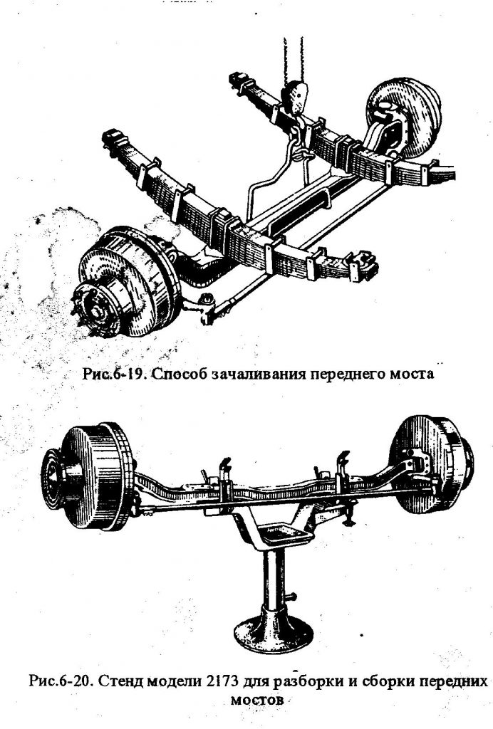
Disassembly of the front axle. The method of mooring the bridge is shown in Fig. 6-19. Install and securely fasten the front axle assembly with the tie rod and brake chambers on the disassembly and assembly stand (Fig.6-20).
Remove the tie rod, for which it is necessary to unpin and unscrew the castellated nuts of the tie rod ball pins, press the pins out of the swivel arms and remove the tie rod (Fig. 6-21).
| Video (click to play). |
Bring the brake pads together by turning the clutch (along the axis of the worm) of the adjusting brake lever counterclockwise.
Unpin and remove the pin connecting the fork of the brake chamber rod with the adjusting brake lever.
Unpin the splined end of the expander shaft and remove the washer, adjusting brake lever and adjusting washer from the shaft. For the convenience of removing the lever, it is necessary to remove it from the fork of the brake chamber rod by turning the lever axis.
Unscrew the bolts securing the hub cover, remove the cover and the cover gasket; Remove grease from the bearing lock nut and wipe off the lock nut.
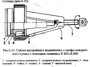
Unbend the lock washer 7 and unscrew the lock nut 5 of the hub bearings, remove the lock washer 7 and the lock ring 8.
Loosen the wheel bearing nut.
Remove with puller mod. And 804.27.000 the hub assembly with the brake drum from the steering knuckle (Fig. 6-22) and remove the cuff 3 from the hub. When removing the hub, the outer bearing is also removed.
Wipe the trunnion surface and inner bearing with a rag soaked in diesel fuel or kerosene.
Remove the outer release springs, press the pads with a mounting blade and remove the rollers. Remove the pin from each axle of the brake shoe, remove the lining of the axles of the shoes, and then dismantle the brake shoes with retractable springs from the axles.
Wipe the axles of the brake pads with a rag soaked in diesel fuel and check the condition of the axles. On the surface of the axles there should not be a significant development (in the form
ring grooves) and wear. If there is a run-out and an axle diameter of less than 27.74 mm, it is necessary to replace the axles by unscrewing the axle nuts and pressing out the axles.
Remove the expander shaft seals from the annular grooves of the bracket. The cuff support ring should only be sprayed if there is a gouge or pitting on the ring surface.
Unscrew the nuts and bolts securing the brake mechanism shield and remove the shield assembly with the shoe axles.
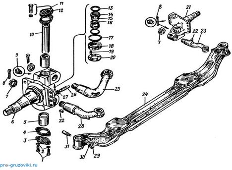
Unscrew the bolts securing the upper and lower covers 27 (see Fig. 6-8) of the king pin and remove the roofs and cover gaskets. Unscrew the wedge fastening nut 28 of the kingpin and knock out the wedge from the hole in the front axle beam.
Press out with tool mod. R-176 or KS-2 or 2504 (Fig. 6-24) the pivot of the steering knuckle 23 (Fig. 6-25) and remove the knuckle 26, the adjusting washer 29 and the thrust bearing 20.
After removing the steering knuckle, remove the seal with the cage from the upper eye, and the thrust bearing 2 from the lower eye! (See Figure 6-18) and support washer.
Loosen and unscrew the slotted nut securing the upper arm 19 and press the arm out of the hole in the steering knuckle eye. This work is performed only for the left steering knuckle. Unpin and unscrew the fastenings of the lower arm 17 and press the arm out of the hole in the steering knuckle eye.
Carry out similar work for the right steering knuckle.
These works are carried out only if it is necessary to replace the levers in case of loosening of the lever fit and wear of the hole in the lever head for the ball pin. Technical requirements for the replacement of steering knuckles are listed below in Table. 6-10. To facilitate unscrewing the castellated nut of the lever fastening and its pressing out, it is recommended to fill the place of fastening of the lever with brake fluid and hold for 3 ... 5 minutes.
Rinse the parts of the hubs, brake mechanism, bearings, swivel pins in a solution of MS-b, MS-8 TU 6-15-978-76, blow them with compressed air.
If it is necessary to replace the pivot bushings, they must be pressed out on a press
If necessary, press the bearing outer races out of the hub.
Press the pivot bushings into the stub axle lugs. After pressing the bushings, stretch them to size 45 + 0.60 mm. When pressing the bushings, the hole in the bushing must match the hole (oil channel) in the steering knuckle eye.
Press in with mandrels mod. And 806.05.005‚ And 806.05.004 and And 806.05.006 the outer rings of the hub bearings and the cuff into the hub.
If necessary, press the bushings out of the expander knuckle bracket, having previously removed the sealing rings.
Press the bushings into the expander knuckle bracket and turn the bushings to the size of the expander shaft. Install the O-rings into the bracket. O-rings can be installed after fixing the bracket to the brake shield.
Carry out similar work for the right hub and steering knuckle.
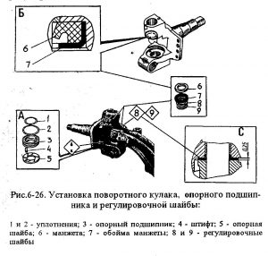
Install cuff 6 with clip 7 into the groove of the upper eye of the pivot pin (Fig.6-26‚b). The cuff should be installed so that its edge is directed towards the end of the beam boss.
Install support washer 5 with pin 4 and support bearing 3 with seals 1 and 2 in the seat of the lower eye of the steering knuckle (Fig.6-26). The support washer pin should fit into the hole in the lug socket.
Adjusting washers 8 and 9 must be selected and inserted between the upper end surface of the beam boss and the lug so that a washer 0.25 mm thick does not enter the adjusted gap (see Fig. 6-26).
Press the king pin, after lubricating it and the bushings with engine oil. The kingpin must be pressed in so that the risk on it coincides with the hole in the boss of the beam under the wedge 28 (see Fig. 6-18).
Insert the wedge 28 of the king pin and tighten the wedge fastening nut with a spring washer. The wedge nut must be tightened with a force of 36 ... 44 N.m (3.6 ... 4.4 kgf.m).
Install and secure the upper and lower kingpin covers with gaskets and tighten the cover fastening bolts with spring washers. Gaskets that are no longer suitable for further use should be replaced.
Lubricate the bushings of the left steering knuckle with Litol-24 GOST 21150-87 grease through grease fittings until grease appears from the gaps of the mating parts.
Install the brake shield on the steering knuckle flange and tighten the nuts of the bolts securing the shield to the flange.
Install the expander knuckle bracket on the shield and tighten the nuts of the bracket fastening bolts with spring washers. The bracket mounting bolts must be secured with wire.
If the axles of the brake pads were removed, insert them into the holes in the shield and tighten the nuts of the axles of the pads. Lubricate axles with grease Litol-24 GOST 21150-87. Do not tighten axle nuts.
Put the internal release springs on the pins of the shoes and install the shoes on the axle. Put a slip on the axle of the pads and lock each axle with a pin. The axle pins must securely hold the pad on the axles of the pads.
Carefully, without damaging the O-rings, install the expanding fist into the bracket. Press the brake pads with a mounting spatula and insert the rollers.
Install the outer spring braces on the brake shoe pins. Insert the upper swivel arm with the key into the hole in the upper eye of the swivel pin, tighten and cotter the lever fastening nut. Tighten the fastening nut with a force of 400 ... 500 N.m (40 ... 50 kg cm). Re-use of the pin is not allowed.
Carry out similar work for the right side of the steering knuckle.
Install and secure the tie rod, the nuts of the ball pins of the tie rod must be cottered. Re-use of pins is not allowed.
Check and, if necessary, adjust the pivot angles (Fig. 6-27). Adjustment must be made using the stop bolts. The maximum angle of rotation must be:
when turning to the left: 45 + 30 ′ - for the left trunnion; 43+30′ — for the right trunnion;
When turning to the right: 45 + 30 ′ - for the left trunnion; 43+30′ - for the right trunnion. Press the support ring 13 (see Fig. 6-17) of the hub cuffs, the thrust ring and the inner bearing onto the trunnion
- After pressing on, lubricate the bearing with Litol-24 grease.
Install hub 2 complete with brake drum and outer bearing 9 of the hub.
Before installation, the bearing must be lubricated with Litol-24 grease. When installing the hub, be careful not to damage the cuff 3.
Screw on the bearing fastening nut, then turning the wheel in both directions, tighten the nut, tightening torque 60 ... 80 N.m (6 ... 8 kgf-m). Then unscrew the nut by 1/4…|/3 turn (90…1200) until the nut pin coincides with the nearest hole in the lock ring. Install the lock washer, tighten the lock nut, torques 250 ... 300 N-m (25. .30 kgf-m), and bend the lock washer to one of the No. When checking, the wheel should rotate evenly and freely in both directions. The gap should not exceed 0.15 mm.
Put Litop-24 grease in the hub cover 2, install it with the gasket on the hub and tighten the cover fastening bolts with spring washers. Cover gasket, unsuitable for further operation, replace with a new one.
Install the brake chamber on the bracket and tighten the chamber fastening nuts with spring washers. Install the adjusting washer, brake lever, flat washer on the splined end of the expanding knuckle shaft and cotter the end of the shaft. Re-use of cotter pins is not allowed.
Perform similar work for the right steering knuckle and hub. Adjust the brake mechanisms of the front wheels in the following order:
loosen the nuts for fastening the axles of the pads and bring the eccentrics together by turning the axles with marks to each other (the marks are placed on the outer ends of the axles protruding above the nuts);
- loosen the brake chamber mounting bolts;
- pull the adjusting brake lever so that the pads are pressed against the brake drum;
- center the pads relative to the drum, turning the eccentrics in the direction of the pad movement towards the brake drum. This ensures that the pads adhere to the drum, which can be checked with a feeler gauge through the windows in the brake drum. A probe 0.1 mm thick should not run along the entire width of the lining;
- without releasing the adjusting lever and holding the axles of the pads from turning, securely tighten the nuts of the axles and the bolts of the brake chamber bracket;
- release the adjusting lever and connect the fork of the brake chamber rod to the adjusting lever with a finger, the finger must be cottered, having previously installed a washer on it;
- turn the worm axis of the adjusting lever so that the stroke of the brake chamber rod is 15 ... 25 mm. Ensure that the strokes of the rods of both brake chambers are the same.
The drums should rotate freely and evenly without touching the shoes.
WATCH THE VIDEO
- Posts: 347
- Location: Rostov region, mines
- ZIL 5301 Bull
help with advice on how to knock the king pin out of the beam. I tried everything, and warmed and knocked, and pressed the press, it doesn’t work at all. Goby 2005 Beam of a new sample.
the wedge did not forget to unscrew and knock out.
- Posts: 347
- Location: Rostov region, mines
- ZIL 5301 Bull
I unscrewed everything, both the wedge and both covers. Filled everything with brake fluid, it can sour overnight.
- Posts: 4119
- From: Rostov region
- ZIL 5301 Bull
ZiS 101
oleg 1969, November 30, 2012, 6:01 pm, #1
help with advice on how to knock the king pin out of the beam. I tried everything, and warmed and knocked, and pressed the press, it doesn’t work at all. Goby 2005 Beam of a new sample.
Removed the beam or try to knock it out on the spot
oleg 1969, November 30, 2012, 6:48 pm, #3
I unscrewed everything, both the wedge and both covers. Filled everything with brake fluid, it can sour overnight.
vinegar is better, it easily penetrates and decomposes (acid is still) and in this case it is better to roll out the beam with springs.
warmed, by the way, in vain if slightly - it will not help, to red - you will ruin it ..
Looks like it's been refurbished and it's pretty bad.
- Posts: 4119
- From: Rostov region
- ZIL 5301 Bull
ZiS 101
Yes, you don’t need any vinegar, you don’t need to heat it, you just need an emphasis under the beam so that it doesn’t spring, i.e. hard
Some, out of inexperience, try to knock out on a jack
OLEGator, November 30, 2012, 07:04 PM, #6
Yes, you don’t need any vinegar, you don’t need to heat it, you just need an emphasis under the beam so that it doesn’t spring, i.e. hard
Some, out of inexperience, try to knock out on a jack
I agree, it’s not about rust, it’s necessary to roll it out and knock it out on a good support with a heavy sledgehammer (I’m talking about vinegar, because it’s better than brake fluid, which is hygroscopic and the result can be the opposite, especially overnight.)
- Posts: 347
- Location: Rostov region, mines
- ZIL 5301 Bull
tried to knock it out on the spot. I welded a frame from a channel, put a jack on top of the glass from below directly into the king pin, and nothing. Sitting dead.
why the jack from below into the kingpin. there is no place on site to swing the sledgehammer in a straight line, roll out the beam, unscrew it - 10 minutes. and you can easily knock it out, you need to knock the kingpin down!
- Posts: 347
- Location: Rostov region, mines
- ZIL 5301 Bull
when assembling, the steering knuckle on the kingpin should turn by hand, with effort, but turn and pay attention when you buy spare parts that the kingpin and bushings must be of a new type by 38, and the bushing should also be 1.5-2 mm thick. costs somewhere around 200-250 rubles. just eat the same at 38 but thin and somewhat cheaper, otherwise it will be weakened and go for spare parts 2p (still not vodka. ))
- Posts: 7
- From: SAINT PETERSBURG
tell me how to break through the lower grease fittings on the pivot. otherwise the upper ones are injected and the lower ones are somehow not injected
- Posts: 328
- From: Krasnodar
- ZIL 5301 Bull
ZIL 5301 Goby Ref
December 27, 2012, 04:57 PM #13 + 1
kondrakhinsv-82, December 27, 2012, 11:45 am, #12
tell me how to break through the lower grease fittings on the pivot. otherwise the upper ones are injected and the lower ones are somehow not injected
unscrew the grease fitting and unscrew the tip on the syringe. If the thread and diameter of the tube fits the thread for the grease gun, then screw the syringe tube instead of the grease gun and inject insolently. If it does not fit, then clean (wash) the grease fitting, lift this side with a jack. Another option is to find a syringe at services or in motorcades that works from air, it will gouge any snot for you.
- Posts: 6
- GAZ Gazelle 3302 Magipulator
ZIL 5301 Bull MANIPULATOR
TELL A BEGINNER HOW AND WHAT to iron the bushings in the size of the steering knuckle, otherwise the kingpin does not go at all.
- Posts: 96
- From: Samara
- ZIL 5301 Bull
AYKHAL 31, January 29, 2013, 20:43, #14
TELL A BEGINNER HOW AND WHAT to iron the bushings in the size of the steering knuckle, otherwise the kingpin does not go at all.
- Posts: 6
- GAZ Gazelle 3302 Magipulator
ZIL 5301 Bull MANIPULATOR
alexey63rus1, January 29, 2013, 08:49 PM, #15
- Posts: 513
- From: Morshansk
- Renault Logan
ZIL 5301 Bull
AYKHAL 31, January 29, 2013, 20:55, #16
- Posts: 6
- GAZ Gazelle 3302 Magipulator
ZIL 5301 Bull MANIPULATOR
BYCHKOVOD, January 29, 2013, 09:02 PM, #17
OK, ATO NOT KNOWING A FULL AMBUSH))).
- Posts: 30
- From: rossosh
- ZIL 5301 Bull
hello guys, no one needs a beam without one hub, it’s like not killed, I just bought a bull when the owner gave the old one and I have a new sample if you write in a personal
- Posts: 13570
- Location: 66, Yekaterinburg
- UAZ Hunter 315195
ZIL 5301 Bull
January 29, 2013
AYKHAL 31, January 29, 2013, 21:07, #18
OK, ATO NOT KNOWING A FULL AMBUSH))).
bushings that are clogged are not in size, initially squandered (marriage) with a ball to drive away in order to crush it should work.
It didn’t work out for me, I drove them away with a ball, but they still sat weakly, I did it differently, at the bronze turner I turned bushings with an interference fit, cooled the bushing, and warmed the knuckle (places for bushings) and hammered it with a mandrel, the bushings sit dead at such a landing when everything cools down (even knocking out a problem), and then deployed it, it turned out very well. it is better to spend time and do it qualitatively and for a long time
- Posts: 6
- GAZ Gazelle 3302 Magipulator
ZIL 5301 Bull MANIPULATOR
vadim20, 29 January 2013, 21:19, #20
bushings that are clogged are not in size, initially squandered (marriage) with a ball to drive away in order to crush it should work.
It didn’t work out for me, I drove them away with a ball, but they still sat weakly, I did it differently, at the bronze turner I turned bushings with an interference fit, cooled the bushing, and warmed the knuckle (places for bushings) and hammered it with a mandrel, the bushings sit dead at such a landing when everything cools down (even knocking out a problem), and then deployed it, it turned out very well. it is better to spend time and do it qualitatively and for a long time
It's also an option, I agree. It's better to do it right once.
- Posts: 18
- From: armavir
- ZIL 5301 Bull
Mitsubishi Lancer 10
Good afternoon. Bull 2004, mileage 153 thousand. Please tell me, all our Armavir masters just shrug their shoulders. the car scours the road in different directions. it was all broken in front of the chassis! the chassis was repaired (salen blocks, all rubber bushings were replaced, the right kingpin was 30.1, and the left repair lawn was 30.14. they were dead. replacement of the crosses on the steering column, maintenance gura (with a polished head), the fingers are new on the springs, the steering rods are tightened, checked, the rear springs are also moved and everything is new there!. The hub bearings are adjusted, there is no backlash. The rubber is all imported new. it was impossible to drive at all after the repair, after the repair 60 km per hour and then you go on treason, you catch it constantly. the beam was not checked for deformation and twisting, it was not possible. maybe there is a problem in it? and the machine arbitrarily slightly deviates.
- Posts: 234
- From: Samara
- ZIL 5301 Bull
nick82, 10 February 2013, 20:45, #22
Good afternoon. Bull 2004, mileage 153 thousand. Please tell me, all our Armavir masters just shrug their shoulders. the car scours the road in different directions. it was all broken in front of the chassis! the chassis was repaired (salen blocks, all rubber bushings were replaced, the right kingpin was 30.1, and the left repair lawn was 30.14. they were dead. replacement of the crosses on the steering column, maintenance gura (with a polished head), the fingers are new on the springs, the steering rods are tightened, checked, the rear springs are also moved and everything is new there!. The hub bearings are adjusted, there is no backlash. The rubber is all imported new. it was impossible to drive at all after the repair, after the repair 60 km per hour and then you go on treason, you catch it constantly. the beam was not checked for deformation and twisting, it was not possible. maybe there is a problem in it? and the machine arbitrarily slightly deviates.
look at the frame, most likely it is spreading along your traverses, or it has cracked somewhere
- Posts: 328
- From: Krasnodar
- ZIL 5301 Bull
ZIL 5301 Goby Ref
nick82, 10 February 2013, 20:45, #22
Good afternoon. Bull 2004, mileage 153 thousand. Please tell me, all our Armavir masters just shrug their shoulders. the car scours the road in different directions. it was all broken in front of the chassis! the chassis was repaired (salen blocks, all rubber bushings were replaced, the right kingpin was 30.1, and the left repair lawn was 30.14. they were dead. replacement of the crosses on the steering column, maintenance gura (with a polished head), the fingers are new on the springs, the steering rods are tightened, checked, the rear springs are also moved and everything is new there!. The hub bearings are adjusted, there is no backlash. The rubber is all imported new. it was impossible to drive at all after the repair, after the repair 60 km per hour and then you go on treason, you catch it constantly. the beam was not checked for deformation and twisting, it was not possible. maybe there is a problem in it? and the machine arbitrarily slightly deviates.
The convergence may not be clearly set. And if the beam is damaged, then convergence is just an option to fix it. I don’t catch up with what kind of crabs?
And my car always rushes in different directions, already used to it
Still a little thought, but didn’t they upset the beam under the kingpin with a sledgehammer? If so, then as an option, the collapse was shot down. Although, if the collapse was knocked down, then it should pull in one direction, but not throw it.
ADJUSTING THE BEARINGS OF THE PINS OF THE VEHICLE ZIL-131
When adjusting the preload of the front wheel bearings of the car, it is also necessary to check and, if necessary, adjust the preload of the bearings 5 and 14 (see Fig. 45) of the pivots 4 and 17 of the pivot pins.
The need to adjust the bearings can be checked without removing the front drive axle from the vehicle. For this
you need to raise the front axle and install it on the goats, unscrew the plug in the bottom cover 16 of the stub axle housing and install the indicator on the cover, directing its leg to the end of the kingpin. Using a jack or lever, move the body of the pivot pin upwards, and if there is an axial clearance, then the movement of the indicator arrow will show the presence of axial movement in the bearings.
Before adjusting work, additional operations should be performed in addition to those that were carried out when adjusting the wheel bearings. First you need to disconnect from the
gate levers longitudinal and transverse steering rods, then disconnect the air supply hose to the tire and remove the wheel. Completely unscrew the bearing fastening nut 32, remove the wheel hub 35 as an assembly with the brake drum and remove the brake pads 22. Disconnect and remove the adjusting lever 6. Disconnect the angle fitting from the support disk and unscrew its base from the air supply head 37. Remove support disk 20 and expanding fist 40. Remove trunnion 36 and take out half shaft II complete with half shaft 29 and air supply head 37, and remove all seals that may interfere. At the same time, you should check the condition of seals 9, 10 and 23, as well as blow compressed air through channel 31 for air supply to the tire.
To eliminate the axial clearance of the bearings of the pivot pins, it is necessary to tighten the nuts 1 and 15 of the fastening of the upper cover 3 with a lever 8 and the lower cover 16 of the bearing to failure.
cov. Then, with a dynamometer, the hook of which is inserted into the hole in the steering trapezoid lever (Fig. 46), determine the torque required to rotate the pin from one extreme position to another. If the torque is in the range of 0.5-0.6 kGm, which will correspond to a force of 2.0-2.4 kg, then the bearings do not need to be adjusted, and the bearings must be lubricated with grease.If the required torque is out of the specified limits, it is necessary to change the thickness of the set of shims 7 and 13 (see Fig. 45) up or down. With a weak tightening of the bearings, the set of upper and lower shims 7 and 13 is reduced by the same amount, and with a strong tightening, they are increased.
The set of shims under the covers to ensure the alignment of the pivot pin and ball joint 12 must be the same or, in extreme cases, differ by no more than one shim 0.05 mm thick. Axial clearance of bearings is not allowed.
When eliminating the axial clearance resulting from bearing wear, it is recommended to remove the required number of shims 13 from under the bottom cover, since the bottom bearing usually wears out more. If, during disassembly of the assembly, it turned out that the wear of the bearings is approximately the same, you need to remove the same number of gaskets from under the top and bottom covers. In case of severe wear of the lower kingpin bearing, it is recommended to swap the bearings; in this case, the gaskets must be removed from under the top cover.
When installing new bearings, you must first measure their mounting height (from the bearing end of the outer ring to the bearing end of the inner ring). The total thickness of the shim set installed on the side of the larger bearing must be greater by the difference in mounting heights of the bearings. Failure to comply with the above rules for installing shims leads to a loss of alignment of the stub axle housing and the ball joint.
When adjusting the preload for new bearings, each set of shims must include at least ten 0.1 mm thick shims. In this case, two gaskets with a thickness of 0.05 mm and one gasket with a thickness of 0.1 mm must be installed in the set of gaskets on the side of the axle shaft housing 29, and the remaining thin gaskets on the side of the covers. This makes it possible to obtain a tight (leaky) connection.
In the process of adjusting the preload of the bearings, it is necessary to turn the body of the stub axle in one direction and the other so that the rollers of the bearings of the pivots occupy
correct position between the inner and outer rings.
Having finished adjusting the pivot bearings, it is necessary to assemble the assembly in the reverse order of disassembly and fix the assembly parts with bolts and nuts. In this case, spring washers should be placed under the nuts, and split cones 2 should be put on the studs.
Rice. 46. Method for checking the preload of the bearings of the kingpin of the front axle of the ZIL-131 car
1. Using a special mandrel (see Fig. 1), press the bushings into the holes of the steering knuckle flush with the surface so that the open ends of the grooves on the bushings face the inside of the knuckle (the pressing force must be at least 10 kN). The pressed-in bushings should not protrude above the ends of the installation of the sealing collars in order to avoid their undercutting.
The lubrication holes in the bushings must match the oiler holes in the knuckles. Iron the bushings to a size of at least 29.55 mm, ensuring their alignment.
2. Install the front axle beam on the stand shown in Fig.2.
3. Insert sealing rings into the sockets of the steering knuckle, into the lower seat - the thrust ball bearing, after lubricating it with Litol-24 grease, and into the upper seat - adjusting shims 8 (Fig. 3).
4. Install the steering knuckle 1 and connect it to the bridge beam by inserting a special mandrel from below into the holes of the fist and the beam (Fig. 4).
5. Check the gap "C" between the upper support of the steering knuckle and the upper plane of the beam support (see Fig. 3). The gap should be no more than 0.2 mm.
If necessary, adjust the gap with shims 8. The total number of shims should not exceed two.
6. Press the king pin on top, having previously lubricated it and the bushings with engine oil. Press the king pin so that the flat on it coincides with the hole in the boss of the beam for the wedge.
7. Fasten the kingpin with a wedge 9, screw a nut with a washer onto it.The tightening torque of the nut must be 28 - 36 Nm. Install the kingpin covers with sealing rings and fix them with thrust rings 18.
8. Screw grease fittings into the holes of the steering knuckles and lubricate the kingpin bushings and bearing with Litol-24 grease until the grease comes out of the gaps of the mating parts.
The rotation of the fists relative to the beam by hand must be smooth and without jamming at an angle of not more than 45 °.
9. Fix the lower arms on the right and left knuckles, and the upper arm on the left knuckle. The tightening torque of the lever mounting bolts is 160 - 200 Nm.
10. Assemble the tie rod and install it on the lower swing arms, fasten the ball pins with nuts and cotter them. The tightening torque of the lever mounting bolts is 160 - 200 Nm.
11. Assemble the tie rod and install it in place, secure the pin with a nut and cotter it.
In the presence of a special device, adjust relative to the axis 0 - 0 (Fig. 5) the angle (4'. 10') of the installation of the pivot of the steering knuckle (toe-in) by changing the dimension "E", which is achieved by rotating the transverse steering rod.
12. Install the mud shield 11 (see Fig. 6) and fix it with bolts 8 with spring washers.
Copiously lubricate the inner bearing with grease, insert it into the hub, install washer 12 and press in the collar using a special mandrel.
In the event that there is wear on the outer rings of the steering knuckle bearings, they must be replaced. Landing of rings in a nave is made with an interference fit; for the inner bearing - 0.010 ... 0.059 mm, for the outer - 0009 ... 0.059 mm.
13. Install the hub assembly with the brake disc on the steering knuckle c. using a special mandrel (Fig. 7), while the mandrel must rest against the inner ring of the bearing. Lubricate the outer bearing generously with grease and install it on the trunnion using a special driver, while the driver should rest against the bearing inner ring.
14. Install the thrust washer 16, screw on the adjusting nut 15 (see Fig. 6) and tighten it to 60.80 Nm, turning the wheel hub in both directions so that the bearing rollers are correctly installed. Axial play is not allowed, the hub must not rotate after tightening.
15. Then unscrew the adjusting nut by approximately 45° and tighten the coupling bolt 13 of the terminal connection of the adjusting nut 15 to a torque of 16.18 Nm. With this adjustment, the axial clearance in the hub bearings will be about 0.2 mm. In operation, in the case of checking the value of the axial clearance with an indicator head, the clearance should be within 0.125. 0.25 mm.
16. Install cover 2 with gasket and tighten three screws 3 securing the cover.
17. Install the caliper with the hose bracket on the brake disc, install the lock plate and tighten the two caliper mounting bolts.
18. To bend a lock plate of fastening of a brake support.
When installing the front axle on the car, it is necessary to lift the front part of the car frame with a lift and roll the front axle.
29. Lower the frame a little on the suspension.
20. Attach the front axle to the vehicle frame.
21. Lower the front of the car and remove
lifting devices. Then carry out the operations of mounting the front axle on the car, the reverse of disassembly.
In the event that the toe-in and steering angles of the wheels were not checked during the assembly of the front axle, they should be checked and, if necessary, adjusted.
Let's take Fuso Fighter as an example, what to do when you need to replace the king pin?
What were the complaints before the renovation?
Explicit knock hodovki front. Gap, play between the pivot pin and the front beam.
Yes, in this case, indeed, it is necessary to repair, adjustment will not do.
What do we usually do to replace the kingpin?
Remove the wheel first, then the brake drum. By the way, in order to remove it carefully and quickly, you definitely need a special hub wrench. Unfortunately, not all sizes are available in stores, so we have to make many keys ourselves.
Okay, we coped with the drum, let's move on to the brakes ..We remove the brake pads, the brake cylinder can not be disconnected, so as not to pump the brakes later. As far as the hose is enough, carefully remove it to the side so that it does not interfere.
Then remove the covers from the pivots. It's simple. Well, the most difficult and interesting thing remains - to knock out the kingpin and bushings ...
Usually - this is the biggest problem, because. as a rule, the kingpin breaks the trunnion bushings and firmly sticks to the beam! First, we try to knock out the kingpin with a sledgehammer, and gently heat the beam with gas. If it doesn’t go well, then you need to remove the front beam and use the press to drive the king pin out ..
This time we managed with a sledgehammer. This is good. We turn to the pivot pin, press out the bushings. Here you definitely need a guide (drill) of a suitable size. By the way, it is needed 2 times: to pull out the old bushings and put in new ones. We also make different punches ourselves. They are not sold in stores.
Okay, we changed the bushings in the trunnion, now we lubricate them a little and begin to drive the kingpin.
When finished, then we check very carefully: there should be no backlash or gaps between the trunnion and the beam! Everything must be very tight! Otherwise, the king pin and bushings do not last very long! And you will need to change them again.
Now squirt until the lubricant appears. If the grease bottle is clogged, then it must be changed, otherwise how to inject?
Then we put the brake cylinder, collect the brake pads in place. We put on the brake drum .. And then be very careful - it's time to tighten the wheel bearing. Why is it so important?
If you overtighten it, it will get very hot and quickly break! Will have to change it again!
Well, if you don’t hold out the wheel bearing, then the wheel will hit left and right, back and forth .. It’s hard to steer, and the bearing will quickly break again ...
Well, well, we tightened the wheel bearing. Checked. They did everything right. They put on the wheel and handed over the truck to the owner.
By the way, we put original Japanese ones on this Fuso king pin. Since they go twice as long as Korean or Taiwanese, and the price differs by only 500 rubles
My master punches the bushings with balls, he has 3 of them + -size, it can work with a cutter, but I have never seen it (changed it 2 times). Maybe I'm wrong - correct me.
Right. Consistency has nothing to do with it. If only the kingpin did not hang out.
- Like
- I do not like
So I think maybe I can order some kind of turner in order to catch alignment or is it not very important?
Alignment is important or they won’t walk for a long time, in order to keep it read above, Alex correctly writes how to do it. Can be done without a ball.
ALEX89, I wrote in detail, excellent, I just forgot to clarify - I need a long sweep. I personally could not find one, there are only short ones.
Everything is done with the usual scan, I don’t know the length, about 25 centimeters by eye. And I haven’t seen others on sale.
Diesel, another blowtorch or gas, otherwise you’ll beat the hell out
If you squirt sometimes, then they normally knock out.
ALEX89, I wrote in detail, excellent, I just forgot to clarify - I need a long sweep. I personally could not find one, there are only short ones.
Literally today I saw in auto parts on the Moscow Ring Road in the Details of GAZ Machines near Vagonoremontnaya Street. It costs a little over 1,000 r. There was a short one, they cost about 400 re.
Maloli will be useful to someone in Moscow.
- Like
- I do not like
- Like
- I do not like
- Like
- I do not like
- Like
- I do not like

Guys tell me where who is in Moscow time. did you buy reinforced kingpin caps? https://my.housecope.com/wp-content/uploads/ext/3317/forum/public/s. I was in Russia and Kemp yesterday, but not there. https://my.housecope.com/wp-content/uploads/ext/3317/forum/public/s.
Southern port. A set of covers with gaskets is about 300 rubles (if memory serves)
Just have to rearrange the oilers from the old covers.
- Like
- I do not like
- Like
- I do not like
Guys tell me where who is in Moscow time. did you buy reinforced kingpin caps? https://my.housecope.com/wp-content/uploads/ext/3317/forum/public/s. I was in Russia and Kemp yesterday, but not there. https://my.housecope.com/wp-content/uploads/ext/3317/forum/public/s.
as I understand it, chtol squeezes them out, why reinforced? I took an old army belt and made two spacers out of it, and like a grandmother hissed.
- Like
- I do not like
Thank you all very much for your help.
I managed to release the pivots with acetone + tad 17. I installed reinforced covers. What kind of grease should I lubricate?
There is a small problem - there is no rubber band on the left side between the beam and the hub, on the right side there is. Is it deadly?
need advice:
acetone + tad 17 how long to keep, and where should it leak from?
is it possible to pierce the pivot groove with a solvent (in the sense of oil + solvent is it scary or not?)
I apologize for the questions, but in this matter I am a “nerd”, if possible, I ask you to answer in detail, going into details, if not difficult.
While you are hanging out here, you would have punched a groove long ago, even with kerosene, even with acetone, there is no difference, as long as your flushing takes place. You can try TAD 17. Any liquid. And preheat with a hair dryer. This will facilitate the process of washing and punching. And warm up the oil too. The advice is real, without irony and jokes. Good luck bro.
While you are hanging out here, you would have punched a groove long ago, even with kerosene, even with acetone, there is no difference, as long as your flushing takes place. You can try TAD 17. Any liquid. And preheat with a hair dryer. This will facilitate the process of washing and punching. And warm up the oil too. The advice is real, without irony and jokes. Good luck bro. https://my.housecope.com/wp-content/uploads/ext/3317/forum/public/s.
| Video (click to play). |
Lyokha47, I wrote here, you can pour a bucket of hot water on your fist. and it is better to hang out the face.

