In detail: do-it-yourself shocker repair from a real master for the site my.housecope.com.
One of the most common shocker problems is a missing spark or a constant electric arc instead of a variable one. Also, the capacitor may break in the device, the microcircuit may fail, the battery may oxidize. There are a lot of reasons why a stun gun breaks down. This is moisture ingress, wear of parts and assemblies, improper charging of the device and non-compliance with the operating instructions.
Why is it not recommended to repair a stun gun with your own hands? It's simple: in order to eliminate the malfunction, it is necessary to identify its cause, and an amateur will not be able to do this. The only thing that an ordinary user can do is to install a battery in the device to replace a battery that has failed. All other faults should be repaired exclusively by professionals.
Also, specialized service centers are engaged in repairs, where masters work, who are well versed in the features of such devices and can diagnose them.
There is one caveat: almost all EShUs work according to an individual electrical circuit, and it is difficult to find its description or image. Accordingly, the masters reproduce the circuit only after visual analysis: they disassemble the device and study its internal design. That is why, often after repair, the ESA does not work the way it used to. That is, in many cases it is more expedient to purchase a new device than to repair an old one.
Do-it-yourself stun gun repair
There can be many reasons for repairing a stun gun with your own hands. The main ones are a non-working flashlight bulb in the stun gun, an insufficient charge of the stun gun and, strangely enough, the stun gun pierces the body and, accordingly, beats with current where it is not needed.
| Video (click to play). |
It’s worth immediately at the beginning of the article to make a reservation and say that repairing a stun gun with your own hands is fraught with unpleasant consequences. You can not only completely break the stun gun, but also get a strong electric shock from it. Therefore, if there are no elementary skills in working with devices powered by electricity, then it is better to refuse to repair the stun gun yourself.
Over time, even the best stun gun loses its charge and gradually fails. Therefore, if the reason for repairing a stun gun is insufficient charge or fast discharge, then you should think about this, first of all:
- Perhaps it's time to change the battery in the stun gun;
- The high-voltage converter of the stun gun has failed.
And if the first cause of the breakdown of the stun gun is quite easy to fix with your own hands, then there may be problems with replacing the high-frequency generator in the stun gun.
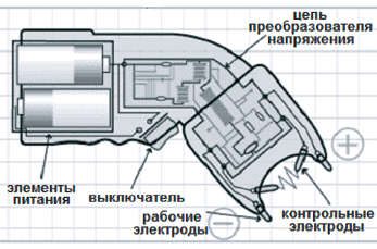
To repair a stun gun with your own hands, you can’t do without knowledge of how a stun gun works. In fact, the work of the stun gun is quite simple. A charged stun gun holds a charge in the battery or batteries, from which, when the button of the stun gun is pressed, a constant voltage is supplied to the transformer.
An alternating voltage comes out of the stun gun transformer, which goes to a high-frequency converter and a voltage multiplier. From the voltage multiplier, the current flows to the external contacts of the stun gun, which are designed to shock the enemy.
If the stun gun is equipped with a flashlight, then if it breaks, you should first check the light bulb. Depending on the model of stun guns, either a light bulb or an LED can be installed in the flashlight. With the replacement of the LED in the stun gun, certain problems may also arise, because it is usually non-removable and soldered to a special board.
The main thing when repairing a stun gun with your own hands is not to forget about safety. A blow over 1000 volts, even if it is short-lived, few people like it. Therefore, before repairing the stun gun, make sure that it is completely discharged.
If this is not the case, then be sure to discharge the stun gun, because only in this way you can not worry about the safety itself when repairing the stun gun with your own hands.
An electric shock device (stun gun), abbreviated as EShU, is a publicly available special means of protection against offenders and an effective means of scaring away and protecting animals, such as dogs, when attacked.
Shockers on the market are presented in a wide range, but the principle of operation of all models is the same. They differ from each other only in the magnitude of the voltage on the electrodes, the power of the arc, reliability and the presence of additional services, such as a flashlight and a built-in charger, and others.
The main consumer parameters of any shocker are the open-circuit voltage on the arrester electrodes and the arc power. According to GOST R 50940-96 “Electroshock devices. General technical conditions.» The voltage shockers on the electrodes are divided into five groups. The first is from 70 to 90 kV, the second is from 45 to 70 kV, the third is from 20 to 45 kV, the fourth is from 12 to 20 kV and the fifth is up to 12 kV inclusive. And according to the power of the impact of the arc - into three types. The first is from 2 to 3 W, the second is from 1 to 2 W and the third, from 0.3 to 1 W.
Depending on the combination of type and group that a particular model of the stun gun has, it can be assigned to one of five classes according to GOST R 50940-96. To which class the stun gun corresponds, it is easy to find out from the table below. For example, a stun gun of the second type of the third group belongs to the third class.
First class stun guns are very powerful and expensive, they are weapons for special forces. For personal protection, a shocker of the second or third class is quite suitable. Shockers of the fourth and fifth class are more suitable for intimidating an attacker than for real protection.
Attention, if you decide to buy a stun gun, then consider the following. For a temporary paralysis of the physical strength of an attacker, the time of continuous exposure of the shocker discharge to his body should be about 3 seconds. With a shorter exposure time, you will only anger the offender and then it is quite possible that you yourself will fall under the influence of your own shocker. It is permissible to use a shocker only if you are sure that you can hold the shocker pressed by the electrodes to the enemy’s body for three seconds.
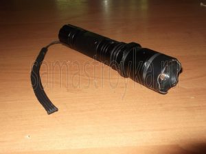
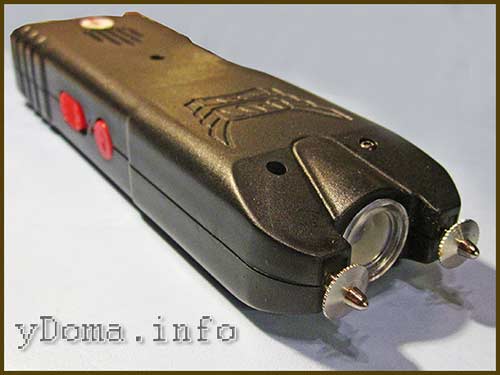
I had to repair a JSJ-704 stun gun with a flashlight. The appearance of this shocker is shown in the photo above. According to external signs, the shocker was in good order, the LED indicating the battery charge was lit when the shocker was connected to the network. The flashlight worked, the ready-to-discharge LED also glowed, but nothing happened when the discharge button was pressed. It became obvious that the fault lies in the high-voltage converter circuit.
All stun guns, regardless of model and manufacturer, work on the same principle. The voltage from the accumulator or batteries is supplied to a high-frequency generator, which converts the DC voltage into an alternating voltage.Alternating voltage is supplied to a step-up high-voltage transformer, the secondary winding of which is connected directly or through a voltage multiplier to the external electrodes of the shocker. When the stun gun is turned on, a powerful electric arc occurs between the electrodes.
The photo shows the electrical circuit diagram of the JSJ-704 stun gun.
The scheme consists of several functional nodes. A GB1 battery charger is assembled on the capacitor C1 and the diode bridge VD1. C1 limits the charge current to 80 mA, the diode bridge rectifies the voltage. Resistor R1 serves to discharge the capacitor C1 through it after the shocker is disconnected from the mains voltage to prevent the discharge of the capacitor through the human body in case of accidental contact with the plug terminals.
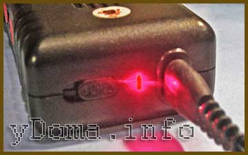
The HL1 LED serves to indicate the connection of the shocker to the 220 V electrical network, R2 serves to limit the flowing current through HL1. This part of the circuit does not directly participate in the operation of the shocker and serves only to charge the battery and may be absent in models of other shockers. Charging time for a fully discharged battery is 15 hours.
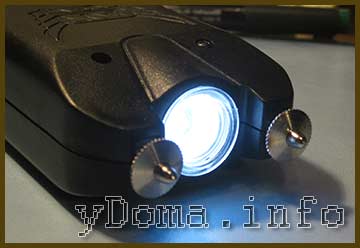
LED HL2 with current-limiting resistor R3 is a flashlight. The lamp turns on when the switch S1 slider is moved to the middle position. The flashlight is placed between the discharger of the shocker and is convenient in the dark. Some models of shockers may be missing.
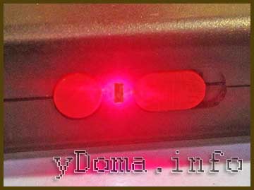
LED HL3 with current-limiting resistor R4 serve to indicate the inclusion of the shocker in the mode of readiness for use. To prevent accidental inclusion in the discharge mode, triple protection is provided in the form of three switches. In order for a discharge to appear between the electrodes, you must first move the sliding switch S1 (located next to the round button) to the extreme right position, then the second sliding switch S2 (located next to the connector for connecting the shocker to the mains for charging) to the right position, after which the HL3 LED will light up, informing that the shocker is ready to be discharged. And only after that, when you press the round pusher of the self-returning button S3 “Start”, a discharge will appear between the electrodes in the form of a blue arc.
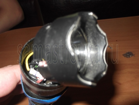
Due to the fact that the halves of the body of the shocker were fastened together with four self-tapping screws, it was not difficult to disassemble it.
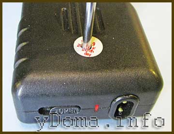
The heads of three self-tapping screws were clearly visible in the hidden holes, and the fourth was sealed with a label. After unscrewing all the screws, the halves easily separated.
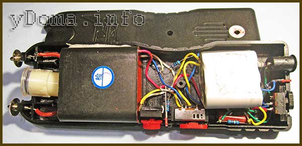
After removing the cover, the following picture opened. As you can see in the photo, the installation of parts of the stun gun is done by a hinged method, there is no printed circuit board. The high-voltage converter is filled with compound. This is good because it is protected from moisture and therefore more reliable, but it is bad that the converter is not repairable. It should be noted that although the shocker is made in China, all soldering is made with high quality and reliability.
Attention, when repairing a stun gun, extreme care must be taken so as not to accidentally touch the discharge electrodes during the operation of the shocker. Kill will not kill, but the discomfort is guaranteed.
Repair of any electronic device begins with checking the power supply. Therefore, the first step is to check the performance of the battery or batteries. The test can be done with a multimeter. If the shocker is powered by batteries, then in addition to their serviceability, you need to check the condition of the contacts in the battery compartment. It happens that they oxidize or weaken their springy properties.
When the “Start” button was pressed with the “Ready” indicator on, the discharge did not occur, but the voltage at the battery terminals, equal to 7.2 V, did not drop. So it's not the battery. I checked the voltage when pressing the "Start" button on the input terminals of the High Voltage Converter, it dropped to a few volts.This voltage was sufficient for the HL3 LED to glow, but not enough for the converter to work.
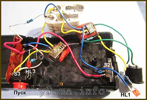
Therefore, the fault was in the poor contact of one of the switches, S1, S2 or S3. I shorted the conclusions of S2 with a jumper and the stun gun worked. To restore the performance of the shocker, you need to clean or replace the faulty switch.
If the stun gun has not been turned on for a long time, then in some types of switches the contacts are oxidized and often it is enough to turn them on and off twenty times to restore their performance. Then the oxide will be erased, and the switch will work again.
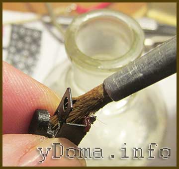
But since the shocker was opened and there was access to the contacts in the faulty switch, the wires were soldered from the switch and the contacts were cleaned with a brush moistened with alcohol. During the time when the contacts were wet from alcohol, the switch was intensively switched. After soldering back to the wire leads, the work of the shocker was restored. As you can see, we managed to repair the stun gun with our own hands, spending very little time.
Here is a video demonstrating the operation of the stun gun after repair. As you can see, a rather powerful arc appears between the electrodes, accompanied by a strong sound of a wide spectrum. Animals, especially dogs, do not like this sound very much; they run away with their tails between their legs.
Hello everyone! Reviews on Mysku of this flashlight or shocker inspired me to buy it as a dog repeller. The device came to me partially working: the flashlight shone, the shocker sparked, but the battery did not charge from the network. Therefore, the lantern was dismantled, as a result, I myself was somewhat shocked by its internal contents, although I assumed that I would see something similar. My review is an addition to existing reviews, that is, a description of the internal structure of this shocker flashlight.
The flashlight I bought after reviewing it was my second order from TinyDeal. An order came to me after about 50 days, a “simple” (in the words of postal workers) parcel without any registration - even mail notifications are not sent to such parcels. This is the first time I received such a package.
Brought home, unpacked, inspected, checked. The flashlight works, the shocker sparks very loudly, which is exactly what I needed. Of the defects, I immediately noticed a crack on the plastic glass that covers the flashlight, and in general the glass itself is somehow unclear. He shook the lantern - like nothing was hanging inside him.
I involuntarily experienced the shocker on myself when I pressed the "start" button once, without making sure that the "shocking" was turned off. It so happened that I was holding the flashlight by the body, and my hand slightly went over the “crown” of the flashlight. The electric shock was strong enough, without a spark discharge, and the campaign broke through the plastic of the crown, since I did not touch the contact plates. I have been repeatedly shocked by voltage sources from 110 volts to 30 kV (the scars have not disappeared yet), and in general I am not very sensitive to this, since the skin on the fingers is quite rough. I estimate the “shocking” effect of the flashlight as quite strong, approximately equal to an electric shock from a 220 volt network. 380 volts hit me only once, and this was perhaps the most dangerous case. The kilovolts in this shocker are purely for the visible effect, and so that the clothes are pierced. If the goal is to shock, not spark, then a voltage of 500 volts would be enough, given that this will increase the current strength significantly. Well, the place of application of the current is very important.
After playing with the flashlight for a bit, I did not bring it to a full battery landing, but still decided to charge it: it was interesting what happens when you plug the flashlight into the mains for charging. It turned out - nothing! Nothing at all! The LED on the end of the flashlight handle did not light up, and by all indications, charging was not going on. Okay, I check the lace (who ever thought of making the cord so short?!) - the cord is in order. So why isn't it charging? Flicked the switches - the result is zero.The review says that charging from the network goes only when the switch on the end of the handle is “On”, but in my case nothing has changed.
Without much hesitation, I unscrew the two self-tapping screws that secure the plastic back of the lantern to the metal one. With a little effort, I remove this plastic part from the lantern. And there…
I took pictures after I took everything apart, so some of the pictures come as if “ahead of it”.
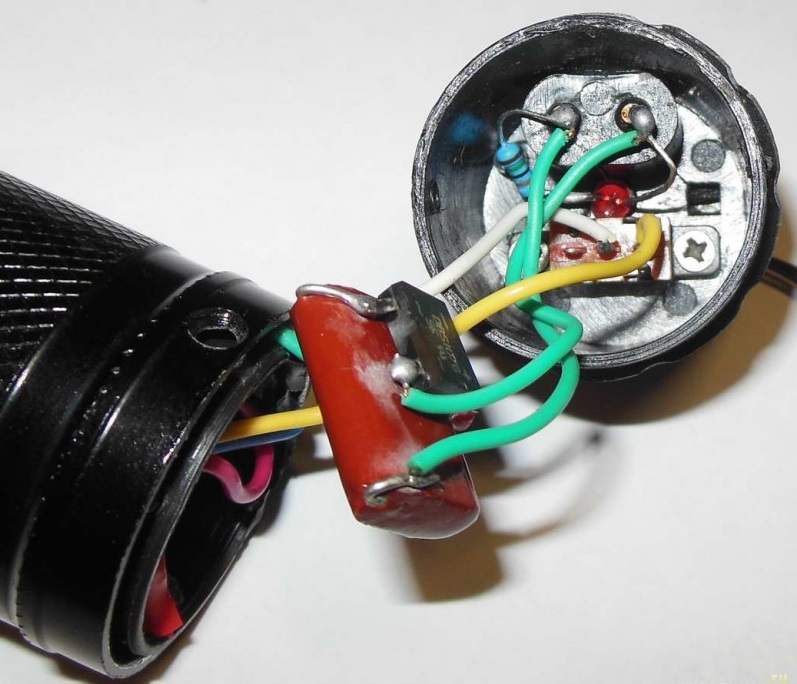
I haven’t seen such a collective farm for a long time ... the wires from the terminals for connecting the charging cord are soldered to the capacitor and the rectifier assembly hanging on the capacitor leads. The wires from the output of the rectifier assembly go deep into the device.


The capacitor even crumbled the case material due to excessive bending of the output.
And the main thing is that all this is not isolated by anything, even just a coil of electrical tape over a conder with a rectifier. If we consider that the wires are thin, and the quality of the insulation does not suffer, then it is quite possible to expect a short circuit and fireworks. There is no fuse. Self-tapping screws protruding inside the lantern, fastening the back cover, can also lead to a short circuit inside the lantern. It’s good that at least the wire connections to the BB converter are isolated, I would check what is there, soldering or twisting, but I forgot to do this.
Next, we look more closely inside the back cover, and we find that the charge indication LED is soldered through a resistor to the terminals, that is, it should light up immediately when external power is applied, and burn all the time while the flashlight is connected to the network. The review says that the LED goes out when the battery is charged - is there really a charge controller in that lamp? I doubt something, maybe there is an inaccuracy in the review? Well, it’s clear that the switch does not need to be switched to “On” for charging, it is included in the BB generator circuit, and not battery charging.
But why does the LED not light up when external power is applied? It is unlikely that it is faulty like this, since new. Ah... Here's the thing... The LED, along with the wire going to the rectifier, just fell off the terminal stupidly: bad soldering. Well, it’s clear now why there is no charge, and the LED does not light up. Solder.


But since I partially dismantled the lantern, I could not stop there. Moreover, I have already seen the end of a plastic cylinder, inside of which two wires went. I guessed that this was a 400kV high voltage generator, as its description on Aliexpress says (review But if there is a voltage converter, then where is the battery? I pulled the voltage converter towards me - it didn’t really resist, and I decided that the high-voltage wires long enough that I could take out the transducer, and indeed I took it out, but only with the BB wires, which turned out to be very short, and which I, it turns out, ripped out of the "crown" of the lantern. It was a surprise, because I thought that the BB the wires are soldered to the contacts, but it turns out that soldering is an unaffordable luxury in this case (in Chinese).
Well, I tore it out and tore it out ... It's impossible to put the BB wires back without further disassembly, so I continue to gut the lantern. From the side of the handle you can see a plastic part - the holder of the button and switch, fixed with a retaining ring.
Just in case, I twisted the BB wires, leaving a gap of about 1 cm between their ends - if I decide to check the operation of the BB converter, it will not burn out due to an excess voltage at the output, which would be if the ends of the wires are separated in different directions. I could not stand it, and checked the disassembled discharge - there is a discharge.
But how to remove the plastic "crown" from the lantern? Moved it, I feel a slight backlash. At first I thought that the crown was glued, but it turned out that two self-tapping screws were hidden under a black strip with an inscription pasted on the edge of the metal part of the lantern. I peeled off the strip, unscrewed the screws, removed the crown, and after it a plastic “bucket” with an LED fell out onto the table, as well as a very remarkable battery.
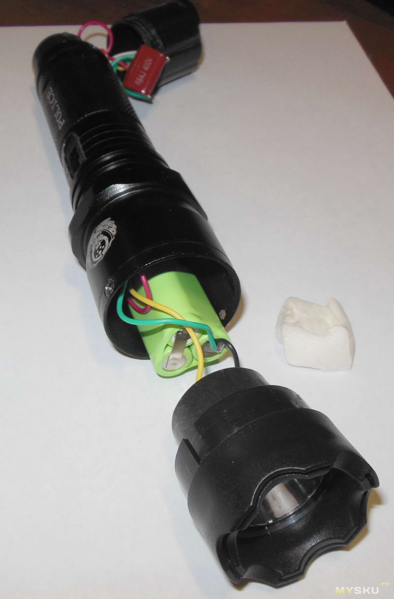
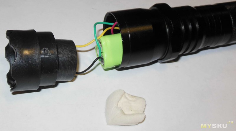


At first, looking at the battery, I was very surprised: was it really produced in 2010? But for bourgeois, the first digit is usually the year of manufacture, and it turns out that the battery comes from 2013. Since the flashlight arrived charged, then perhaps the battery is not so bad, at least in terms of self-discharge. Its type and capacity from the "FEIYU 3.6v 1" marking are unclear, but it is 100% nickel-cadmium, and for three of its series-connected cans, I measured about 3.8V. What capacity can it be? To prevent the battery from dangling, it was pressed with a fabric pad (visible in the photo). No insulation, not even one layer of electrical tape.
Also, there is no insulation at the super-duper LED driver - resistor, and a moving resistor could easily short out the battery. But the fact that the resistor is present, as I understand it, is already good, sometimes they don’t put a cut. Wrapped some electrical tape around the rezyuk.


I understood the reason for the appearance of a crack on the glass of the lantern: this is a self-tapping screw that entered the side surface of the transparent “cup”. The reason is the crooked installation of the “glass” - if it is placed evenly, the self-tapping screw only slightly touches its end, and does not lead to cracks.


Began to collect the lantern back. When disassembling, I completely in vain removed the “snap” (slider) from the flashlight mode switch, and the plastic sleeve with the switch and the shocker on button turned inside the flashlight housing.
At the same time, the top of the button popped out, and it took me some effort to return it to its place, turn the sleeve to the desired position and put the slider on the switch.
I must say that during the fuss with the disassembled flashlight, I was mentally prepared for the fact that poorly soldered wires would fall off the switch or button, but nevertheless the soldering withstood, even though I pulled the wires in the process of examining the flashlight.
I stuffed the high-voltage generator back into the body of the lantern, stretched the wires to the crown. When screwing the back cover, the screws pass through the plastic of the high-voltage generator housing, preventing it from chattering. The wires to the aluminum contact inserts in the crown are not connected in any way, the design simply provides some small distance between the BB wires and the crown contacts. At the same time, it is impossible to guarantee whether or not there is an electrical contact - this is the will of chance. If there is contact now, then with strong vibration, shock of the lantern when the wires fall, they can “run away”, and an extra spark gap will appear. At the explosive wires of my generator, the cores were even slightly deepened into the insulation, respectively, in addition to the visible external discharge, small discharges also occurred along the way inside the plastic crown, as evidenced by the burn marks left by the discharges on the aluminum inserts. To prevent aluminum inserts from popping out during vibration, etc., it is advisable to grab them with glue.


To increase the likelihood of electrical contact between the BB wires and the plates, I cut the insulation so that about 0.3 mm of the central strand of the wire sticks out of it, inserted the wires into the holes in the crown, and hoisted the crown into place. This operation had to be repeated, because a couple of times when installing the crown, the wires slipped out of my destinations. There is no way to fix the wires better, as they are too short. It was possible to drip glue, but I didn’t, you never know you have to disassemble (almost for sure).
Well, everything seems to be ... The lantern has been assembled so far, everything works, shines, sparks, but has not yet charged, and the main question is how long it takes to charge this battery of unknown capacity. If anyone has worked with this and knows its capacity, please tell me. I did not find any similar ones.
Even before opening the lantern, I wrote on TinyDeal that the lantern was faulty, not charging, I attached a couple of photos in which the lantern is plugged in, and the “charging” LED is off. The reaction of the store was interesting. In general, after some dispute with TinyDeal, I was offered a $7 refund in the form of TD points.Or, when ordering over $45, TD promised to send another such flashlight-shocker free of charge, which is very strange: this flashlight has had the “sold” status for a long time. Since I already looked after one flashlight on TD (just a flashlight, without a shocker), I agreed to a refund of 7 bucks, especially since I don’t plan to buy anything big there in the near future.
Maybe someday, if I can get my hands on it, I'll remake this flashlight for a lithium battery with a USB charging controller and a normal LED driver, and maybe with a different LED. True, in order to put a more powerful LED, it will be necessary to grind a heat-removing adapter to replace the native plastic holder. The main question is what kind of lithium-ion battery or battery of batteries will fit here, what format? Certainly not 18650, so perhaps installing a more powerful LED does not make sense.
Perhaps the first modification of the flashlight will be its alteration to charge the battery from a voltage of 5V from USB, you just need to install a resistor, maybe even plug a mini-USB connector into the flashlight. The charge time will be decently reduced, although this time will need to be controlled by yourself, but most importantly, the likelihood of fireworks when charging from the mains will decrease. Haven't done it yet.
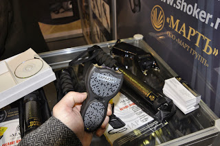
Before buy a stun gun, most buyers wonder how difficult it will be to repair in case of breakdown. Before buying a shocker, sellers are asked questions about the terms of the guarantee and the availability of service centers no less than questions about the features of the weapon and the methods of its use. These questions sound about the same and do not depend on either the gender or the age of the person who has decided buy a shocker.
But the answers to them may vary, depending on where and what shocker you buy. Sellers Chinese devices and shockers produced in nameless artels and workshops will assure you that any master of any workshop will cope with the repair of the shocker. But, they will add, you won’t need to repair it, since the “manufacturer guarantees”, etc. etc. Meanwhile, they carefully avoid the question of what exactly the manufacturer guarantees and where “any workshop” is located, where you could go in case of a breakdown. You will also not receive clear contact details and any other information about the manufacturer and service centers.
This is understandable: such shockers were produced and brought into the country illegally. And, of course, no one will take responsibility for their quality and repair.
But repair difficulties are not the only and not the main problem that you may encounter. First of all, such a purchase automatically makes you a lawbreaker. The Law of the Russian Federation "On Weapons" allows citizens to buy and use as weapons of self-defense only shockers produced in Russia by licensed manufacturers. Thus, buying a Chinese or unlicensed shocker, you breaking the law.
If you still decide to buy a shocker, turning a blind eye to the requirements of the law (they say, no one will know), then you will face another problem. Counterfeit shockers either not effective enough as a weapon of self-defense, or, conversely, can be deadly.
The effectiveness of the shocker depends on the balance of its characteristics such as power, voltage, sparking frequency. An imbalance in one direction or another turns the shocker into either a useless "rattle" or a deadly device.
To maintain this balance, official manufacturers conduct rigorous research before putting a shocker model into production. Careful control is also carried out at all stages of production. All this requires the use of modern expensive equipment and high-quality electronic components.
Of course, underground manufacturers will not bother with all these issues. Their goal is to sell you weapons. And how effective it will be, they no longer care.
But that should be your concern.Buy shockers only from official Russian manufacturers. By doing this, you will protect yourself from many problems, both legal and criminal.
Moreover, the repair of such shockers will not cause you any inconvenience! The Mart company offers unique conditions for warranty service of its products: if during the warranty period (2 years) any flaw is found in the shocker, Mart simply replace it with a new one.
For any questions regarding the performance of the warranty, please contact Service center, or by the contacts indicated on the company's website.
We wish you safety!
stun gun - the device is very useful, but what is sold in the store will not protect you in real "combat" situations. It is worth recalling once again that according to GOST, civilians (mere mortals) cannot wear and use electroshock devices whose power exceeds 3 watts. This is ridiculous power, which is only enough to scare away dogs and drunken drunks, but not for defense.
An electroshock device must be highly effective in order to protect its owner in any situation, but alas ... there are no such devices in the store.
So what to do in this case? The answer is simple - to assemble a stun gun with your own hands at home. Some of you may be wondering: is it safe for attackers? It's safe if you know what to collect. In this article, we will offer a shocker that has a titanic output power of 70 watts (130 watts peak) and can lay down any person in a split second.
In the passport data of industrial electroshock devices, you can see the parameter - EFFECTIVE EXPOSURE TIME. This time depends on the power. For regular 3-watt shockers, the exposure time is 3-4 seconds, but naturally no one has yet been able to hold it for 3 seconds, because due to the negligible output power, the attacker will quickly figure out what the matter is and attack again. In this situation, your life will be in jeopardy, and if there is nothing to defend yourself, then the consequences can be tragic.
Let's move on to assembling a stun gun with our own hands. But first, I want to say that this material is presented on the network for the first time, the content is completely copyrighted, thanks to a good friend Evgeny for the suggestion to use a push-pull multiplier in the high-voltage part. The series multiplier (often used in shockers) has a rather low efficiency, in which case the power is transferred to the body of the attacker without much loss.
Below are the main parameters of the stun gun:
Stun guns are durable and reliable devices that can provide your effective protection for more than one year. But technology is technology and sometimes it breaks down. In this case, our specialists are always ready to help you!
Repair of electric shocks is one of the main directions of our activity! If for some reason your weapon has ceased to function or does not work correctly - hand it over to us and you will receive a fully functional device back!
Usually the cost of repairing a stun gun ranges from 350-700 rubles, the user receives a serviceable weapon within 2-3 days from the moment we received it. But sometimes, due to improper operation and non-compliance with the charging instructions, the device may become completely unusable - it will be impossible to repair the shocker.
But even in such a situation, we do not leave our customers! We can exchange your failed spark gap for a brand new working taser at an additional charge that varies by model.
In some cases, repairing a stun gun is unprofitable for various reasons. If you do not want to waste extra time, but want to immediately get a new weapon instead of a broken one, just contact us by phone and we will tell you the amount of the additional payment and other nuances!
We always try to find a solution to the problem that will be the most profitable and convenient for you!
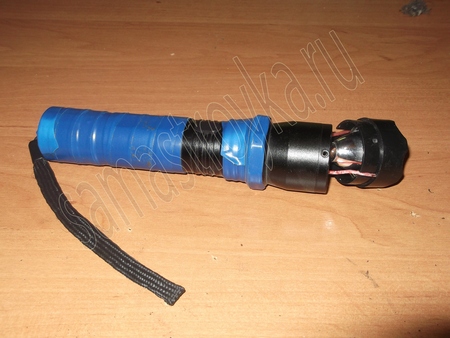
The stun gun is an excellent weapon for self-defense. Today it can be bought by any individual who is 18 years old, it is quite legal! The shocker does not require additional documents from the buyer and its use is legal. The stun gun is intended for active defense against robbers and hooligans, but everything is not so simple. The fact is that the law of our country does not allow us, mere mortals, to wear stun guns with a power of more than 3 watts. The voltage of the shocker (arc length) does not matter and is intended only for breaking through clothes, it follows that a shocker with a voltage of several million volts in a difficult moment can turn out to be just a toy. Really powerful shockers use only organs, if you have a “police” shocker, you can not read this article, and I ask everyone else to warm up the soldering irons and prepare parts for the device.
I present to your attention the design of a stun gun with a power of 7 - 10 watts (depending on the power source), which you can do with your own hands. The design was selected as the simplest so that even beginners can handle it, the selection of parts and materials is also available to beginners.
The voltage converter is made according to the blocking oscillator circuit on a single transistor, a reverse conduction field effect transistor of the IRF3705 type is used, which allows you to squeeze “all the juices” from the power source, IRFZ44 or IRL3205 transistors can also be used, there is almost no difference. Also, you need a 100 ohm resistor with a power of 0.5-1 watts (I used a 0.25 watt resistor, but I strongly advise against repeating my mistake).
The final and most important element of the converter is a step-up transformer. For the transformer, a core was used from a switching power supply from a DVD player. First, we remove all the old windings from the transformer and wind the new ones. The primary winding contains 12 turns with a tap from the middle, that is, first we wind 6 turns, then we do it, we twist the wire and wind 6 more turns in the same direction on the frame, the diameter of the primary winding wire is 0.5 - 0.8 mm. After that, we isolate the primary winding with 5 layers of transparent adhesive tape and wind the secondary. Both the primary and secondary windings must be wound in the same direction. The secondary winding contains 600 turns of wire with a diameter of 0.08 - 0.1 mm. But we wind the wire not in bulk, but according to special technology!
Every 50 turns we put insulation with adhesive tape (in 2 layers), so the transformer will be reliably protected from breakdowns in the high-voltage winding. A transformer wound using this technology does not need to be filled, although just in case it can be filled with epoxy. We solder a stranded insulated wire to the terminals of the secondary winding. It is desirable to install the transistor on a small aluminum heat sink.
After the converter is ready, it needs to be tested. To do this, we assemble a circuit without a high-voltage part, there should be a “burning current” at the output of the transformer, if it is, then everything works. Next, you need to solder the voltage multiplier. Ceramic capacitors have a capacity of 4700 picofarads, the capacity is not critical, the main thing is to choose capacitors with a voltage of at least 3 kilovolts. With a decrease in the capacitance of the capacitors, the frequency of the discharges increases, but the power of the shocker decreases, with an increase in capacitance, the frequency of the pulses decreases, in return, the power of the shocker increases. The diodes in the multiplier need high-voltage type KTs106, they can be obtained by breaking the Soviet TV multiplier or simply bought on the radio market.
Next, we connect the multiplier to the converter according to the diagram and turn on the shocker, the arc should be 1 - 2 cm (if you use all the ratings that are indicated in the diagram). The shocker emits loud pops with a frequency of 300 - 350 Hertz.
As a power source, you can use lithium-ion batteries from mobile phones with a capacity of 600 mA, it is also possible to use nickel batteries with a voltage of 1.2 volts, four nickel-metal-hybrid batteries with a capacity of 650 mA were used in my design, due to a powerful field-effect transistor Batteries work under heavy load (close to short circuit), but nevertheless their capacity is enough for 2 minutes of constant operation of the shocker, and this is a lot for such a compact and powerful stun gun!
Installation - is carried out in any convenient plastic case (fortunately, I had a suitable case at hand from the old Osa stun gun). The high-voltage part of the circuit must be coated with silicone (for reliability). A cut-off fork, nails or a screw will serve as bayonets. The stun gun must be supplemented with a switch and a button without fixing, this is necessary to avoid self-switching in your pocket.
In the end, a few words about the parameters of the shocker - the voltage on the arresters is over 10 kilovolts, the breakdown of clothes is 1.5 - 2 cm, the average power is 7 watts, the shocker is also supplemented with a built-in charger and an LED flashlight, the charger circuit is taken from a Chinese LED flashlight. The switch has three positions, the LED must be connected to the power source through a 10 Ohm resistor (so as not to burn the LED).
| Video (click to play). |
This shocker turned out to be quite compact due to the multiplier and is quite suitable for our beloved ladies. Compared to factory-made stun guns that are sold in stores, our stun gun is much more powerful, and if you still want to increase power, you can increase the power to 7.2 volts, because. A lot also depends on the capacity of the batteries.

