In detail: do-it-yourself repair of a mini jaguar 281 sewing machine from a real master for the site my.housecope.com.
Sewing machine "Mini Jaguar" is a compact, lightweight and economical model designed for home use.
The device of the sewing machine Mini Jaguar:
1. thread guide
2. thread guide
3. thread guide
4. presser foot pressure adjustment screw
5. foot
6. needle plate
7. pull-out table
8. Needle clamp screw
9. spool pin
10. bobbin stop
11. flywheel
12. spool pin
13. carrying handle
14. presser foot lifter
15. electrical cord socket
16. fabric advance mechanism
17. yarn former
18. power cord
19. pedal
Upper thread tension regulator - 21. Using this regulator, reduce or increase the tension of the upper thread. The larger the number, the greater the upper thread tension.
The selected stitch scale is 23. This scale indicates the selected stitch pattern and the width of the zigzag stitch.
Speed range switch 25 on a Mini Jaguar sewing machine. The Mini Jaguar sewing machine has two speed ranges: the slow range is for complex sewing at low speeds, and the second range is for normal sewing at high speeds.
Lever for adjusting the stitch length/backtacking - 24. To adjust the stitch length, loosen the nut on the handle by turning the nut counterclockwise. Move the lever between the numbers 4 and 0, re-fix the handle with a nut. When performing a backtack, lower the lever below “O” and sew in the opposite direction.
Start / Stop switch - 22. On some models of the Mini Jaguar sewing machines, the Start / Stop switch is located directly above the needle, in addition to the speed range switch. With the speed range selected, press the switch to start the machine. To stop the machine, press it again.
| Video (click to play). |
The presser foot lift mechanism is 20. There are three positions for the presser foot:
1) When sewing, lower the presser foot down.
2) when feeding or removing the fabric, raise the lifting mechanism to the middle position.
3) when replacing the presser foot or removing thick fabric, raise it to its highest position.
1. If sewing machine Mini Jaguar has a start/stop switch, make sure it is in the stop position.
2. Make sure the speed range switch is in the off position.
3. Insert the plug of the power cord into the socket on the machine 15 and connect the power cord to the socket.
How to operate the Mini Jaguar sewing machine.
a) Set the speed range switch to the "High" or "Low" position.
b) If the machine has a “Start/Stop” switch, set it to the “Start” position. c) Step on the pedal with your foot to drive the machine. To stop, take your foot off the pedal.
Attention: If you have to stop working or sewing for a long time, unplug the power cord from the outlet. If the machine stops due to the thread getting into the shuttle, for safety reasons, the power supply is interrupted automatically for 20-30 seconds. To resume operation, after a 3-minute break, turn on the power switch again.
Removing the drawer/accessory drawer. You can remove the sliding table by moving to the left. When installing, move the table back until the pins fit into the holes in the machine body. Accessory drawer can be opened by lifting the lid up and back.
Bobbin cap. Open the bobbin cover by moving downwards away from you.Use your index finger and thumb to grasp the latch of the bobbin case. Pull the bobbin case towards you. When the latch is lifted up, the bobbin itself will fall out of the bobbin case.
Place the felt disk on the spool pin and place the bobbin on the spool pin. Pass the thread from the spool through the bobbin thread tightness adjustment tensioner. Pull the end of the thread through the special hole in the bobbin. Place the bobbin on the winder pin so that the end of the thread comes out slightly from the bobbin. Move the winder rod to the right until it clicks.
Start the machine with the speed selector in the "Low" or "High" position. Release the thread after a few turns of the bobbin. Note: keep your hands away from the needle when the machine is running. When the bobbin stops spinning with thread wound, turn off the power. Pull the bobbin pin to the left to remove the bobbin.
Inserting the bobbin into the bobbin case. You need to install the bobbin with your right hand, so that the thread moves in a clockwise direction. Insert the bobbin into the bobbin case so that the thread comes out about 10 cm. Pull the thread into the slot in the bobbin case and then pass it under the flat tension spring.
Installing the bobbin case in the shuttle. Take the bobbin case by the latch. Move the bobbin case to the middle spindle of the bobbin. Note: Make sure the locating pin is fully seated in the locating slot at the top of the hook.
Release the latch to lock the bobbin case. Raise the presser foot lever. Raise the needle to its highest position by turning the handwheel towards you. Thread the upper thread in the following order, according to this diagram.
Raise the presser foot lever so that the thread can pass between the upper thread tension discs. Raise the take-up lever to its highest position by turning the handwheel towards you. Hold the end of the thread with your right hand and pull the thread through the thread guides as shown. Thread the thread in the take-up lever from left to right. Thread the needle from yourself to the back, pulling the thread 10 cm through the eye of the needle.
Receiving thread from the bobbin. Raise the presser foot lifter up. Hold the top thread loose with your left hand. Turn the handwheel toward you with your right hand until the thread take-up lever reaches the top position again. Pull the thread from the bobbin while pulling the end of the top thread with your left hand. Pull the thread from the bobbin until the end of the thread passes through the hole in the needle plate. Pull both threads under the foot. The sewing machine is now ready to go.
Performing straight stitches with a Mini-Jaguar sewing machine.
1. Set the stitch length to 4 mm, thread tension to 3. Raise the thread take-up lever to its highest position by turning the handwheel towards you.
2. Pull the ends of both threads under the presser foot away from you.
3. Place the fabric under the presser foot and lower it to the lower position.
4. Turn the handwheel of the machine until the needle pierces the fabric under the foot.
5. Switch the speed control to the "low" or "high" position.
6.If the machine has a start/stop switch, turn it on.
7. At the end of sewing, the machine must be stopped, to continue working, press the Stop / Start switch again.
8. Turning the handwheel by hand, raise the needle up.
9. Remove the fabric under the foot by cutting the ends of the thread.
10. The cut ends of the threads are pulled under the foot, leaving a free end of each thread 10 cm.
Fastening a stitch on a Mini Jaguar sewing machine. Secure the stitches with lever 24, back-tacking with a few stitches in the opposite direction. To do this, set the stitch length lever to a position below the “0” mark.
This is what this sewing machine looks like disassembled. As you can see, it has a lot of plastic parts, many of which can be damaged under heavy loads.Take care of the machine and sew on it only thin fabrics recommended by the instructions.
Sewing machine manufacturers
You do not know which sewing machine to buy and figure out which sewing machine company is better? All well-known brands of modern sewing machines are of fairly high quality. Choosing a sewing machine, first of all, you need based on your needs. Perhaps an ordinary economy-class sewing machine from any manufacturer is what you are looking for.
Which sewing machine to buy
Sewing machines, including Jaguar firms, radically differ from each other only in the type of shuttle used. For household sewing machines, there are only three of them: sewing machines with a vertical hook; sewing machines with a horizontal hook and machines with a swinging hook. Which of these shuttles is better and how it differs, you will find out in this article.
Sewing machine on credit
Buying household appliances on credit has become so easy that sometimes you can get a loan right in the store with only your passport. Unlike many “useless” purchases, a sewing machine can become a source of income and quickly recoup the costs of its purchase and interest on a loan.
How to open a mini-studio
Many people think that opening an atelier is difficult and requires a considerable amount of money. Not at all, it is enough to have several household machines and an overlocker and some other sewing accessories. You can rent a room in a “sleeping” area. In such areas, there will definitely be a lot of clients for your atelier if you have “golden hands”.
Types of sewing hook
If you are going to buy a sewing machine, first of all, decide what type of hook it should have. For rare home use, a swinging type of shuttle is suitable. For those who often sew for themselves and to order, you need to buy a machine with a rotating shuttle.
Do you have a sewing machine and love to sew? Then this site is for you. Professional masters will tell you how to carry out minor repairs to a sewing, knitting machine. Experienced technologists will share the secrets of tailoring. Review articles will tell you which sewing or knitting machine to buy, an iron mannequin and many other useful tips you will find on our website.
Thank you for viewing the page in its entirety.
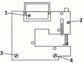
Compact electric zigzag sewing machine. The body of the machine is plastic and consists of two halves. They are fastened with four screws: short screws at the top 1 and 3 (rice. 164), long screws at the bottom 5 and 4. Screw entry from the back. When assembling, you must first be able to lower the screws into a deep hole 5 and 4, which must fall into their threaded, vertically standing bushings, then put the short screws in the deep holes in the same way 1 and 3.
Rice. 164. Appearance (from the back side) of the Jaguar sewing machine:
The electric motor of the Jaguar sewing machine has the following technical data: D = 36 mm, 1 (without pulley) = 57 mm, power - 15 watts. For comparison: the Polish electric motor TUR-2 has a power of 90 watts. The entire sewing machine is 95% plastic. Even the shuttle is made of two materials - the belt is made of metal, everything else is made of plastic.
The shuttle is right-handed, swinging in a vertical plane.
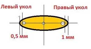
In order to set the desired distance from the shuttle to the needle when it is in its lowest position (and this distance on the left prick of the zigzag is 1 mm), the following operations must be performed:
- Remove the electric motor with the transformer block.
- Remove the needle.
- Take the feed dog - the tissue feeder to the upper position and fix it.
- Loosen the two screws securing the shuttle housing.
- Raise the shuttle travel housing along with the left end of the horizontal drive rack that drives the shuttle pusher.
- Slightly skew the left side of the shuttle travel housing upwards and carefully disengage the rack-drive with the pinion.Here, exercise maximum attention and caution so as not to break the plastic toothed rack-drive, which is hinged with a plastic rivet to a vertical plastic lever.
- Move the gear rack-drive 1 tooth to the right or left (decide locally) in engagement with the spur driven gear of the shuttle pusher.
- Put the shuttle travel housing in place, attach it with two screws, put the needle, lower the needle bar to its lowest position and see what is the distance between the shuttle nose and the needle. If the shuttle nose is 5-7 mm to the left of the needle or 3-4 mm to the right, repeat the whole operation from the beginning.
If the nose of the shuttle is 3-4 mm to the left of the needle or 1-2 mm to the right, fine-tune the position of the shuttle. Loosen the screw for adjusting the position of the shuttle relative to the needle and, by shifting the gear rack-drive to the right or left, set the distance between the needle and the nose of the shuttle to 1 mm.
Place the needle on the right zigzag prick. Bringing the nose of the shuttle to the needle, achieve their meeting at a distance of 1 mm above the upper edge of the eye of the needle. Adjust by moving the needle bar vertically. Here there are difficulties in that for the inner nut of the adjusting screw of the needle bar level, a hex socket wrench is needed, and the edge width is 1 mm. There is nowhere to take it, and it is not attached to the car. Therefore, it is better to replace it with an ordinary screw without a head with an M4 thread. How can you maintain a machine with such an unprecedentedly complex adjustment (adjustment)?
The shuttle in diameter and height (axis) corresponds to the shuttle from the Chaika machine. But the height of its girdle is 3.5 mm, and the height of the girdle of the shuttle of the Chaika machine is 4.5 mm.
The needle bar is of very low hardness and has a play in the frame, which is clearly felt by hand, this is clearly unacceptable for a sewing machine. The needle is closely offset to the back wall in the needle hole.
It is necessary to remove the needle bar and bend it forward by 0.4-0.5 mm. To remove the needle bar, it is necessary to: remove the shuttle travel housing, lower the feed dog - fabric feeder and remove the needle bar down. When installing the needle bar, you must again catch the gear connection of the lower plastic rack-drive of the shuttle with the cylindrical gear.
When sewing, the result is not a straight line, but a wavy line.
The block of copy disks is made integral with the driven gear (rice. 165).
Rice. 165. Detail - plastic driven gear with a block of copy disks (Jaguar machine):
The mechanism of the JAGUAR sewing machine differs from the mechanisms of other models produced at that time. Let's see how it's set up.
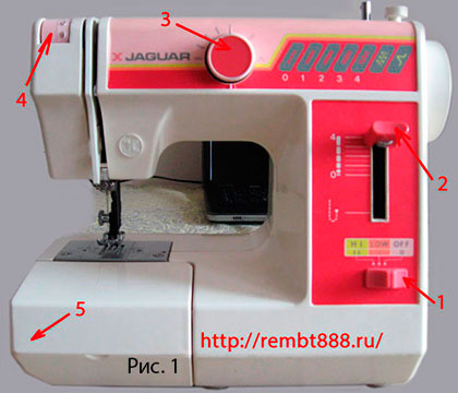
On fig. 1 shows a front view. Here: 1. machine switch for three positions - from right to left - off, average speed, maximum speed; 2. Stitch length regulator; 3. Stitch selection knob; 4. Upper thread tension regulator (RNVN); 5. Removable table-pencil case.
Stitch length dial constantly spring up. On its rod there is a thread along which, during rotation, the adjusting nut moves. When rotated clockwise, the nut moves deeper into the machine, thereby reducing the length of the stitch. In the same way as on Podolsk 2M or Chaika 3, only there is an arbitrary installation due to the poppet washer.
Automatic handle switch with a click stitch width also changes with a click, that is, by a certain distance. There is no separate width adjuster on this machine.
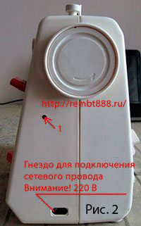
Let's go further, on the side of the machine has a socket for connecting to a 220V network. The number 1 marks the hole through which, on some models of machines, we have access to the fastening of the stitch length regulator lever. see fig. 2. Flywheel does not have a friction mechanism, so winding the thread on the bobbin is not particularly convenient on this machine. There is also no jack for connecting the pedal.
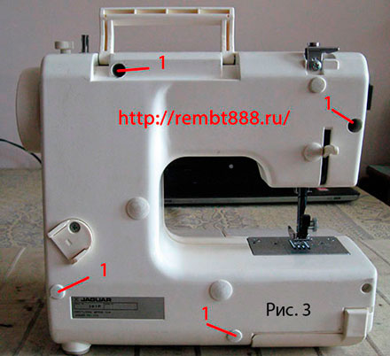
The rear view is shown in fig. 3. At the very bottom is a plate with data about the machine. Almost all holes are closed with plugs, but for disassembly we will need to unscrew only those marked with the number 1.A mounting device is visible on the machine stand, a reel seat is inserted into it.
In work, sometimes you need to flash something narrow. On this machine pencil case very easy to remove, just slide it to the left. It also needs to be removed to replace the bobbin, as it blocks access to the shuttle.
Figure 5 shows a close-up of the machine control knobs. The arrow on the shuttle shows the place where the needle gets in case of incorrect adjustment or large play in the mechanism for transmitting movement from the main shaft to the shuttle.
Needle damage to the hook is a common occurrence in this model. If this happens, then the machine immediately began to skip, break the upper thread.
The upper thread clings to the sharp edges of the potholes, which also does not favor the good operation of the machine.
If you suddenly have to disassemble such a model, then pay attention to Figure 6.
This is how the hex screwdriver should be inserted into the bolt securing the stitch length adjustment knob.
Sometimes the fastening mechanism with its bolt looks to the right, then the answer must be inserted into the hole from the right side.
Attention! Do not try to disassemble the body products until you unscrew the fastening screw and remove the stitch length knob.
Before we start disassembling the JAGUAR sewing machine, it is necessary:
- remove the needle;
- remove the paw. Here, the foot with the holder is made as a single unit;
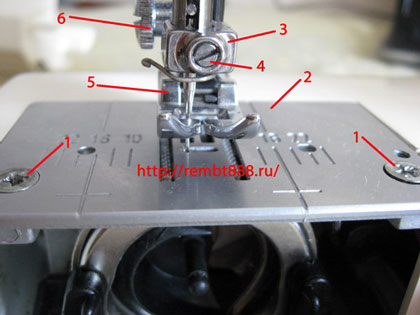
- remove the needle plate by unscrewing the two screws. On this machine, we need a Phillips screwdriver.
1. Fixing screw; 2. Needle plate; 3. Needle holder; 4. Needle clamp screw; 5. Foot; 6. Presser foot screw.
Figure 7 shows the same assembly, only with dismantled parts.
If you have the same machine, and not only this one, after you have removed the needle plate for cleaning, maintenance, etc. - check the tightness of fastening fabric conveyor. The fastening screws are indicated here by the number 5.
The feed dog (4) itself must be exactly in the middle of the slot in the needle plate and be strictly parallel to the edges of the hole. If this rule is not observed (fulfilled), then it is necessary to loosen the fastening screws, achieve the above and tighten both screws tightly.
Well, now let's look at the reason for the owner of the mini Jaguar sewing machine to be repaired. Figure 8 shows a close-up shuttle. Here we see that the surface of the shuttle at the needle entry point and picking up the nose of the hook of the needle thread very badly damaged. Such a shuttle needs to be changed. But since the shuttle here has a thinner working surface, it will not work with another model of the machine. I had to restore this shuttle. If possible, large potholes were removed, all edges and edges were rounded and polished, the nose of the shuttle was polished, but until the whole machine was assembled, it was not possible to check the operation of the shuttle.
After all (four) screws, marked with the number 1 in fig. 3 you need to lift the front cover and remove the connectors shown in fig. 9. The blue connector wires lead to the speed switch and will prevent us from removing the front cover.
In figure 10 we see two halves of a sewing machine.
Attention. When you assemble the body products back, be careful when inserting the bolts (self-tapping screws) into place. They can fall into the case and you have to disassemble everything again.
Figure 11 shows a close-up take-up unit. If you have already dealt with sewing machines, you will notice that the thread take-up unit here is different from other machines. The thread take-up itself at one end stands on an axis in the machine body, and its groove is dressed on the crank axis. In this place, the thread take-up can develop a groove in the axis, then there will be a knock and play in the work.
1. Needle bar. 2. Needle bar fixing screw. 3. Connecting lever. 4. Crank 5. Thread take-up 6. Main shaft eccentric. 7. Screw for fastening the connecting arm and the needle bar frame. In this place, the needle bar is adjusted in the lateral position.
Details of the machine stand are shown in Figure 12.
1. Control board
2. Electric drive
3. Worm
4. Automation mechanism.
Since there was a strong backlash in the shuttle drive in the car, I had to remove the board with the transformer, it was screwed with two screws, see fig. 13 to open access to the details of the bottom of the machine.
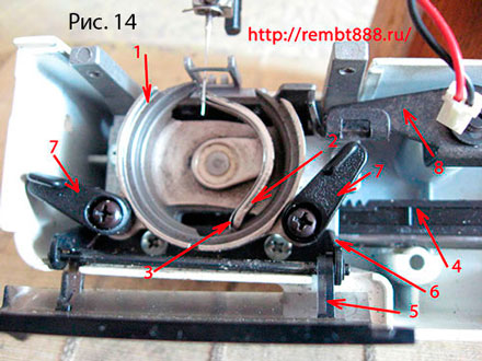
Now access to the details is open, first consider the details of the table on the left side. see fig. 14.
Shuttle housing attached to the back of the machine. Access is blocked by a plug. Shuttle pusher (2) driven by rack (4)
Shuttle device differs from similar ones on modern machines both in the method of fastening, and in size, and in the movement drive. The rail moves in a straight line to the left - to the right. The position of the rail sets the course of the machine.
1. Shuttle body; 2. Shuttle pusher; 3. Pusher spring; 4. Gear rack; 5. Hinged cover of the shuttle compartment; 6. Mounting bracket; 7. Latches of a clamping ring; 8. Conveyor lifting shaft.
If we look at the car to the right. then we will see the adjusting unit and the right end of the conveyor lift shaft. To the right, a clip stuck to the engine housing, which flew off the axis of the connecting lever that transmits movement from the main shaft to the toothed shaft.
Attention. Here's the reason for the crash. A backlash appeared and, accordingly, malfunctions, a clip flew off and a backlash appeared.
By releasing the adjusting screw, you can change the position of the lower end of the connecting lever, respectively, the time of approach of the shuttle nose to the needle changes.
In Figure 16, you can see in more detail the device and the operation of parts in the machine rack.
Connecting lever (1) swings on the axle (2). The stroke is adjusted by changing the position of the lower end of the connecting lever, which transmits the movement to the toothed shaft (5). Below the bolt (3) is a stud that supports the end of the conveyor lift shaft (4).
To the right you can see the connecting lever (fork) of the advance. This fork is responsible for transmitting the movement of the fabric conveyor. In the upper part, it rests on the advancing eccentric, then through the stone it is connected to the link of the stitch length regulator and, at the very bottom, to the crank shaft of the fabric conveyor motor.
To better consider stitch length adjuster remove the limit bar, look
figure 17
1. Regulator yoke; 2. Stone; 3. Lever; 4. Fixing screw; 5. Adjustment knob hole; 6. Eccentric advance.
By changing the position of the lever (3), the position of the regulator gate is changed. The stone in the wings starts moving along a different profile and, accordingly, the stitch length changes.
By swinging the lever (1) Figure 16, holding it in the lower part, you can determine if there is any play in the motion transmission system from the main shaft to the shuttle. If there is a decent backlash in this place, then it needs to be eliminated. The fact is that in the upper part this lever has a cylinder that runs in the groove of a large cylinder mounted on the main shaft, see Figures 18 and 19.
These figures show a device for converting the rotational movement of the main shaft into translational (linear) movements of the rack. The worm (1) of the automation mechanism is also very clearly visible, which is fastened with screws (2) (Fig. 18)
In Figure 19, contour 1 marks the control mechanism for almost all parts of the bottom of the machine. We can clearly see the groove (2) for the connecting lever. The bearing (5) of the main shaft (4) is fixed with a screw (6)
The part highlighted by the contour consists of several parts, made as a whole. Don't touch it unless absolutely necessary.
On the left, the main shaft is shown in figure 20. main shaft (1) is adjusted using a shim (2) which is fixed with screws (3). Main shaft eccentric (4) is attached to the main shaft with a pin (5). The screw (6), which transmits the movement to the thread take-up (7), is painted over so that it does not need to be touched again, and also so that it does not unscrew itself.The connecting lever (8) with the crank moves in the thread take-up and on the cylinder, from prolonged operation, a groove may form and play will appear, which can be eliminated by bending the thread take-up.
When we looked at the case from the back side, we agreed that we only tighten the screws (1), why? Because on the inside they can end with a pin or axle, as in figure 21, positions 1 and 2. The connecting lever (3) on the axle (2) must not have any play and was fastened with a clip that fell off and stuck to the engine. Due to this, a backlash appeared, the course changed and the needle broke the shuttle. The toothed lever (4) on the right side had no play. We rise above - the adjusting unit, everything is fine here too. A little higher is the axis, after fixing this node with a clip, it also began to function normally. If there is a backlash between the cylinder and the groove in the cylinder of the main shaft, then you can get rid of it by bending the upper end of the lever towards you.
The advance shaft (5) transmits the movement to the fabric conveyor with the help of a fork (9) by means of a crank (6).
Presser bar (7) This car is black. The thread take-up is very visible (8)
The drive unit of this sewing machine is shown in Figure 22. Here: 1. engine; 2. fastening screws; 3. toothed belt; 4. Gear; 5. Bracket
Installing this unit on the machine is not difficult, you just need to withstand the condition of ease of movement and lack of play.
Reinstalling the parts that were removed, I think, will not be difficult for you. I got everything in place. The course in this car was selected individually, it turned out to be approximately
2.45 mm. I installed the front cover, connected the electrical wiring and tried to flash it on this machine, you will see the result in fig. 23
As it turned out, the elimination of backlash in the machine parts and the restoration of the shuttle led to a good result.
P.S. What I would like to say in conclusion is that this machine is very delicate, of course, even coarse fabrics can be sewn, but it’s not worth it. It is easy to move it to any place, work on it and clean it, it does not take up much space. The low sewing speed and the lack of a pedal are not very depressing. There are exactly the same machines with a power button on the sleeve and a pedal-button. For a good, permanent job, if someone sews at home, it will not work.
To leave comments you need to register.
You have no rights to post comments
Do-it-yourself jaguar repair —>
Jaguar sewing machine repair
Sewing machine Jaguar JemLux / / Sewing machines / Home appliances / Catalog / Prospect - online store of home appliances in Nov
Jaguar sewing machine repair
sewing machine kitty jaguar reviews
Buy Sewing machine JAGUAR 145 in the online store Reviews, description, characteristics
Jaguar sewing machine repair
Sewing machine Jaguar Instructions for sewing machine Mini Jaguar
Repair of sewing machines Jaguar - Repair of sewing machines and overlockers in Yekaterinburg
SEWING MACHINE LITTLE USED Jaguar 415 — 11 programs 3000 rubles, photo 1 Rostov-on-Don SLANET
Repair of sewing machines in Moscow - Electronics repair
Sewing machine repair mini jaguar
Do-it-yourself Chinese sewing machine repair —>
Review of Jaguar Fantasy sewing machine Even for the money you can buy better
Passport for sewing machine jaguar series 333
Sewing machine Jaguar 620 gallery, photos, installation diagrams
OUR OFFERS
GNTI – Sewing machine Sewing machine Mini Jaguar 281 test winding thread on a bobbin – Video reports from the world of science and technology
On the photo 2, numbers, details of control, machine.
- Switch. Works in three positions - from right to left:
- turned off,
- average speed,
- maximum speed.
- Stitch length knob.
- Stitch selection knob.
- Upper thread tension regulator. (R.N.V.N.).
- Pencil case - for storing paws, bobbins and so on.
On the photo 3, the machine has a socket for connecting to a 220 V network, the engine is installed inside the machine. Pedal, to press the elbow.
First of all, you need:
- Remove the needle.
- Remove needle plate
On the photo 4, shows the knot above the needle plate:
- Fixing screw, needle plate.
- Needle plate.
- Needle holder.
- Screw - needle holder.
- Foot.
- Presser foot screw.
On the photo 5, with a hexagon key 2 - 3 mm in cross section, unscrew the sleeve with an external thread, and under the internal hexagon. – Access to the stitch length lever attachment.
On the photo 6, a screwdriver is shown. To open the car, I had to saw through a screwdriver, a needle file, such a groove.
On the Photo 7 shows the back of the car. Screws 1 and 2 are short, 3 and 4 are long. The top is sealed with corks.
On the photo 8, a kinematic diagram is shown, mini Jaguar cars.
- Flywheel.
- Big gear. Under it, little one.
- Eccentric bushing.
- Fork.
- Plastic drum.
- main shaft.
- Crank.
- Thread take-up.
- Needle bar lead.
- Bracket, with needle bar adjustment screw, vertical.
- Needle bar.
- Needle holder.
- Conveyor block.
- Shuttle adjusting screw.
- Shuttle adjusting screw.
- Shuttle block.
- Conveyor lifting plate.
- Rack.
- Engine.
- Fork pull.
- Electrical board with three plugs and sockets.
- The pressure screw that regulates the pressure of the bar on the plastic drum.
- Plank.
- Finger, when pressed, on the conveyor lift plate.
- Connection with toothed plate.
- Stitch selection knob.
- Worm gear, on the main shaft.
On the photo 9, the arrows show the details of the machine:
- Screw. Lifting plates, conveyor.
- The pressure screw that regulates the pressure of the bar on the plastic drum.
- Push bar.
- Gear rack plastic.
- Promotion shaft, conveyor.
- Eccentric bushing.
- Kernel. Presser foot.
- Thread take-up.
- Thrust - a fork on top, an eccentric on the bottom.
The exhibition of the needle, I produce with respect to the edges, holes in the needle plate. As for the car Seagull 3.
On the photo 10, the location of the needle, on the left and right injection, in the hole of the needle plate. Also in the center.
On the photo 11, shows a block of copiers. Mounted above the worm gear.
On the photo 12, a worm is shown - gear under No. 1.
Lowest, left position, straight stitch. The next position, a small zigzag. Fifth position, large zigzag. See position, stitch selection knobs. Photo 2 No. 3.
- We set the stitch selection knob to the position - the largest zigzag.(there are no failures in this node)
- Install the needle plate in place.
- Turning the flywheel, lower the needle to the left injection, through the needle plate, to the lowest position. At the same time, we have:
- The conveyor block should be under the needle plate at the lowest point.
- The nose of the shuttle should be in position by 1 mm, not gone into the body of the shuttle block. Photo 14.
- Switch to straight stitch.
- Shuttle block spout, must be strictly behind the needle. + - 1 mm.
- The gap between the upper track of the shuttle and the flat of the needle should be 0.1 mm.
On the photo 13, shuttle mechanism it consists of:
- The path along which the shuttle moves.
- Shuttle pusher.
- Buffer spring, on the shuttle pusher.
- Rack with teeth - it rotates the gear - mounted on the axis of the pusher.
- Hinged cover, shuttle compartment.
- Mounting bracket, hinged cover.
- Two clamps, pressure plate.
- Conveyor lifting plate.
- Adjusting screw, position, hook block housing, relative to the needle.
- Adjusting screw, position, hook block housing, relative to the needle.
On the photo 14, the nose of the shuttle should be in position by 1 mm, not gone into the body of the shuttle block.
On the photo 15, view of the shuttle block, from the side.
On the photo 16, shuttle mini Jaguar. The black part is plastic, the rest is metal.
The surface of the hook, at the point where the needle enters and is caught by the nose of the hook, the needle thread, is very badly damaged. Such a shuttle needs to be changed! But since, in this shuttle, the width of the working surface is 3.5 mm. The Seagull has 3.0 mm. Photo 16 - 1, then from other models of cars, more than one shuttle will not work! From Seagull - when installing the clamping ring, the shuttle will overwrite!
On the photo 16-1, width of the working shelf, shuttles.
- Shuttle from cars "Lada 238".
- Shuttle from cars“Seagull”, Podolsk 142″.
- shuttle machine "Chapel 30".
In photo 16-2, the thickness of the shuttles.
- Shuttle from cars "Lada 238".
- Shuttle from cars “Seagull”, Podolsk 142″.
- shuttle machine “Chapel 30”.
I had to restore this shuttle.
- Potholes were removed, all edges and edges were rounded and polished.
- Polished spout, shuttle.
Preparation of the shuttle, for installation in the block.
Blunt nose, shuttle - (this is skipping stitch).
- We sharpen the nose on the reverse side with a blunt, diamond file. Photo 16-3
- Then we bring to the tip of the needle, velvet, sandpaper.
- We remove chamfers, on a vertical plane.
(Sharp chamfers are thread breaks.) From many years of work, on the shuttle, pits, grooves are formed, so we cut them off from the plane. And also polish.
On the photo 16-4, places of processing of the shuttle, from the front side.
On the photo 16-5, places for processing the shuttle, from the back side.
- From all sides, we dull the heel with a diamond, velvet, needle file.
- But we dull the outer path, the inner part of the shuttle, along the entire length, only with velvet paper.
Everything, the shuttle, is ready for installation in the nest.
On the photo 17, assembly with plastic drum:
- Stream.
- The sleeve is a hex screw.
Carbolite drum - consists of two parts.
At the bottom of the drum, there is a pressure bar.
A roller is installed in the pressure plate.
On the photo 18, transfer bracket.
- Push bar.
- The pressure screw that regulates the pressure of the bar on the plastic drum.
- Clamp screw. Adjusts the position of the finger below this screw.
- Conveyor plate.
- Rack. (About the shuttle gate).
On the photo 19, stitch length mechanism, it consists of:
- Regulator yoke.
- A rock. Rusk in the channel.
- Lever arm. Bottom return spring.
- Fastening screw. Hexagon
- Seat, regulator knobs, stitch lengths.
- Eccentric bushing. Under the fork, traction.
By pressing on the seat, the regulator knobs, the spring is compressed. If it were not for the nut (which fixes the position of the handle in one position), on the handle, the handle would rise to the top (photo 5). The position of Rusk in the channel also changes, the fork rises higher, since the axis of the cracker is inserted into the fork. When the main shaft rotates, the eccentric sleeve (6) either presses on the bottom of the fork, or not. This results in a change in stitch length.
On the photo 20, shows the left end of the main shaft. On which, is located - the crank-rod-mechanism.
- Needle bar fixing screw.
- Thread take-up.
- Needle bar lead.
- Connecting bracket, needle bar driver with crank.
- Fastening screw, connecting lever from the copier mechanism with the needle bar frame.
- Crank.
Here are the reasons why the mechanic was called:
- When the screws are loosened, a knock is heard. – Tighten the screws!
- At the bottom of the needle bar, there is a strong play on the sleeve.
The needle bar is made of steel 3. Chrome plated on top.
The bushing and needle bar, the owner of the machine, ordered at the factory.
I replaced. The gaps are gone.
Machine setup complete!
Having put the covers in place, I tried to sew.
The elimination of backlash in the machine parts and the restoration of the needle bar bushings, as well as the restoration of the shuttle, gave their result.
| Video (click to play). |
In custody the machine is 70% plastic and cheap non-hardened metal. Yes, it is light and almost noiseless. It is suitable for teaching in schools. But for home conditions, it is not suitable.

