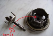
In detail: do-it-yourself bellows repair from a real master for the site my.housecope.com.
The bellows-thermoballoon assembly is designed to close the gas to the main burner when the boiler reaches the set temperature. This device works purely mechanically. The main mechanical meaning of the work of the bellows lies precisely in the stretching and compressing of its “accordion” from the pressure inside the bellows, which increases with increasing temperature. Read more about the device of the bellows and its operation here. If it is not entirely clear what we are talking about here.
It is clear that there are only two options for the operation of the boiler: with defective bellows, or with correct bellows. This will make it easier to explain and understand the following.
How does a boiler with a working bellows work?
Boiler start. The boiler is cold. We close the valve (1) located on the pipeline going to the main burner (if it is open). Only boilers AOGV Zhukovsky are equipped with such cranes. This is done so that when the button (3) of the solenoid valve is pressed, the gas goes only to the igniter. Firstly, this is so that the igniter, so to speak, is set on fire confidently. Secondly, this is due to the possibly low gas pressure, which sometimes drops to 80-60 mbar in severe winters. And it would be nice to "put all the gas on the igniter." Thirdly, at start-up, when the boiler is cold, the “accordion” of the bellows is compressed and the lower valve of the Economy automation unit is always open. His spring squeezes out. Details of the device of the Economy unit are here. Therefore, when the button (3) of the solenoid valve is pressed, gas flows, in addition to the igniter, also to the main burner. And why "divide" the incoming gas into two parts?
| Video (click to play). |
If there are difficulties in understanding what is being discussed now, read about valve equipment.
So. Press the solenoid valve button (3). The gas went to the igniter. We lit the igniter, waited 30-45 seconds and released the button of the solenoid valve. The button must remain pressed. After that, gradually open the valve (1) of the pipeline leading from the unit to the burner. The main burner ignites immediately and the boiler begins to heat up. We set the temperature adjustment knob (2) of the bellows to the desired temperature, say + 60 + 70 C. When the boiler reaches the set temperature, the mixture inside the bellows begins to expand, the “accordion” of the bellows moves apart, presses on the rod and closes the gas access to the main burner. When the boiler cools down, the "accordion" is compressed, the spring squeezes out the lower valve of the block, thereby opening up gas access to the main burner. The burner lights up from a burning igniter. And this process continues until, for example, it becomes warmer outside, and we want to change the temperature in the boiler to a lower one.
Here we are waiting for the first malfunction. More precisely, not a malfunction, but how you can easily and permanently break a perfectly working bellows. When the boiler is hot and you want to lower the temperature - DO NOT TURN THE TEMPERATURE CONTROL KNOB (2) , – let the boiler cool down. Ideally, let the boiler cool down to a temperature slightly lower than what you want to set. It is done like this. We close the valve of the pipeline (1) through which gas flows from the unit to the main burner. In this case, the igniter will remain burning as it burned, and the boiler will slowly cool down. After that, we wrap the thermostat knob (2) to the position we need. Open the faucet (1). It's all. If you start tightening the handle “hot”, you will crush the already weak “accordion”. The boiler is hot, the accordion is open on both sides, there is pressure inside the bellows.And we begin to compress and press on the bellows even more. From the first time, it may even be lucky - the bellows will not burst. And if you do this several times in a row, the bellows fails. This remark applies to all bellows, without exception, both for Russian blocks and imported ones (For example, Eurosit 630 or Honeywell).
Symptoms of malfunction No. 1. When turning the knob of the temperature regulator (2) suddenly smelled something like kerosene. Or else. Clap when tightening the bellows nut “hot”. These are signs that the bellows has broken.
Well, OK. Bellows broken. It happened. How does a boiler work?
How does a boiler with a faulty bellows work?
Moving along the entire chain from starting the boiler “cold” to opening the pipeline valve (1), we will not notice anything special. The only moment. After starting the main burner, the boiler will never turn off again. After this phrase, I even felt sorry for the poor boiler. N-yes. Which will never turn off. So how does it work?
Symptoms of malfunction No. 2. The boiler works “directly”. That is, - the flame on the burner is regulated only by the gas cock (1): more or less. The hot boiler does not react to turning the temperature regulator knob (2).
Such a case. People broke the bellows and clearly saw that the boiler bellows was faulty and decided not to change the bellows-bulb for the time being. And so it was. They began to live on, but there was one big minus. They succumbed to the persuasion of modern masters and cut the circulation pump into the heating, making the circulation in the system forced. They cut off the old open tank, put a modern closed red one.
And here is a miracle! They suddenly turned off the light. The pump, of course, stopped. Nobody at home. The boiler took and rustled up to + 95 + 100С. It wasn't long before the cauldron boiled when someone came. Turned off the boiler. And he gurgles inside. Then it turned out that the light will now be turned off 2 times a week. And, having bypassed all the purchases and cost options, he and his wife decided that putting in a new bellows and saving the boiler when the lights were turned off would still be much cheaper than buying solar panels, a household power station, a uniformer, an uninterruptible power supply, a windmill, etc.
Symptoms of malfunction number 3. (bye guess, – not tested by time). The boiler at the appointed temperature +60 heats up to + 70 and turns off. In principle, everything is fine. There is just some delay. Which, by the way, can then increase up to + 90C, if nothing is touched. Let the boiler cool down. You turn it on. And again, slowly, over time, the shutdown temperature begins to rise.
Here are the answers. If this happens on AOGV-11.6 Economy boilers, then they have an adjusting screw on the bottom of the thermostat nut (2). Read more here. If this phenomenon is observed on boilers with a capacity of 17.4 and above, then it is possible (but not yet confirmed by mass cases) “bites” the lower valve rocker or pin (see complete overhaul and arrangement of the Economy gas block). In any case, when heated, the accordion of the bellows “drives apart” and raises the lever, closing the gas flow going to the burner. If the gas closes late, there is a micro-crack in the bellows. The pressure is not enough. But this is just a guess. This was also observed in imported Honeywell and Eurosit 630 blocks.
Symptoms of malfunction number 4. Applies to those who have boilers in pairs. For example, in the off-season, one boiler always works, while the other one rests. If the boilers are in series, then the bellows of the non-operating boiler must be fully open. . The boiler may not work, but it is hot. The bellows is closed, bursting from the inside, and he has nowhere to go, and he bursts. Therefore, you can keep a new boiler in reserve, in the system, for a long time, and when you start it, you will find that the bellows has already been covered.
As of today, 10/24/2014, these are all the cases known to us related to the malfunction of the bellows-bulb.
Phones for communication:
Operator: 8 (495) 506 81 52
Master: 8 (903) 297 35 57
Didn't call?
8 (909) 240 90 51
127224 Moscow
st. Severodvinskaya 13
Repair of the automation system of the gas boiler AOGV-17.4-3
Recently, the gasification of settlements in Russia has been going on at a rather intensive pace. The main element of the equipment that is installed in every rural house is a gas boiler, the author of this material shares his experience in repairing automation of the AOGV - 17.4-3 gas boiler, popular in rural areas, manufactured by the Zhukovsky Mechanical Plant.
Purpose and description of the main units of AOGV - 17.3-3.
The appearance of the heating gas boiler AOGV - 17.3-3 is shown in rice. one , and its main parameters are given in the table.
Its main elements are shown in rice. 2 . The numbers in the figure indicate: 1- traction chopper; 2- thrust sensor; 3- draft sensor wire; 4- start button; 5- door; 6- gas magnetic valve; 7- adjusting nut; 8-tap; 9-storage tank; 10-burner; 11-thermocouple; 12- igniter; 13- thermostat; 14-base; 15- water supply pipe; 16- heat exchanger; 17-turbulator; 18- knot-bellows; 19- water drainage pipe; 20- the door of the traction control; 21-thermometer; 22-filter; 23-cap.
The boiler is made in the form of a cylindrical tank. On the front side are the controls, which are covered with a protective cover. gas valve 6 (Fig. 2) consists of an electromagnet and a valve. The valve is used to control the gas supply to the igniter and burner. In the event of an emergency, the valve automatically turns off the gas. Traction chopper 1 serves to automatically maintain the vacuum value in the boiler furnace when measuring the draft in the chimney. For normal operation, the door 20 should freely, without jamming, rotate on the axis. thermostat 13 designed to maintain a constant temperature of the water in the tank.
The automation device is shown in rice. 3 . Let us dwell in more detail on the meaning of its elements. Gas passing through the purification filter 2, 9 (Fig. 3) goes to the solenoid gas valve 1. To the valve with union nuts 3, 5 draft temperature sensors are connected. The ignition of the igniter is carried out when the start button is pressed 4. There is a setting scale on the body of the thermostat 6 9. Its divisions are graduated in degrees Celsius.
The value of the desired water temperature in the boiler is set by the user using the adjusting nut 10. Rotation of the nut leads to linear movement of the bellows 11 and stem 7. The thermostat consists of a bellows-thermobalon assembly installed inside the tank, as well as a system of levers and a valve located in the thermostat housing. When the water is heated to the temperature indicated on the adjuster, the thermostat is activated, and the gas supply to the burner stops, while the igniter continues to work. When the water in the boiler cools down 10 . 15 degrees, the gas supply will resume. The burner is ignited by the flame of the igniter. During operation of the boiler, it is strictly forbidden to regulate (reduce) the temperature with a nut 10 - this can lead to breakage of the bellows. You can reduce the temperature on the adjuster only after the water in the tank has cooled down to 30 degrees. It is forbidden to set the temperature on the sensor above 90 degrees - this will trigger the automation device and turn off the gas supply. The appearance of the thermostat is shown in (Fig. 4) .
Actually, the procedure for turning on the device is quite simple, and besides, it is described in the instruction manual. And yet, consider a similar operation with a few comments:
- open the inlet gas supply valve (the handle of the valve must be directed along the pipe);
- press and hold the start button. At the bottom of the boiler, a hiss of escaping gas will be heard from the igniter nozzle. Then the igniter is lit and after 40. 60 and the button is released. Such a time delay is necessary to heat up the thermocouple. If the boiler has not been used for a long time, the igniter should be lit after 20...30 s after pressing the start button. During this time, the igniter will fill with gas, displacing air.
After releasing the start button, the igniter goes out. A similar defect is associated with a malfunction of the boiler automation system. Note that it is strictly forbidden to operate the boiler with the automation turned off (for example, if the start button is forcibly jammed in the pressed state). This can lead to tragic consequences, since if the gas supply is interrupted for a short time or if the flame is extinguished by a strong air flow, the gas will begin to flow into the room.
To understand the causes of such a defect, let us consider in more detail the operation of the automation system. On fig. 5 shows a simplified diagram of this system.
The circuit consists of an electromagnet, a valve, a draft sensor and a thermocouple. To turn on the igniter, press the start button. The rod connected to the button presses on the valve membrane, and the gas begins to flow to the igniter. After that, the igniter is lit.
The igniter flame touches the body of the temperature sensor (thermocouple). After some time (30.40 s), the thermocouple heats up and an EMF appears on its terminals, which is enough to trigger the electromagnet. The latter, in turn, fixes the rod in the lower (as in Fig. 5) position. Now the start button can be released.
The draft sensor consists of a bimetallic plate and a contact (Fig. 6). The sensor is located in the upper part of the boiler, near the pipe for the removal of combustion products into the atmosphere. In the event of a clogged pipe, its temperature rises sharply. The bimetallic plate heats up and breaks the voltage supply circuit to the electromagnet - the stem is no longer held by the electromagnet, the valve closes, and the gas supply stops.
The location of the elements of the automation device is shown in Fig. 7. It shows that the electromagnet is closed by a protective cap. The wires from the sensors are located inside thin-walled tubes. The tubes are attached to the electromagnet using cap nuts. The body leads of the sensors are connected to the electromagnet through the body of the tubes themselves.
A check during the repair of a gas boiler begins with the “weakest link” of the automation device - the draft sensor. The sensor is not protected by a casing, so after 6.12 months of operation it “acquires” a thick layer of dust. Bimetal plate (see fig. 6) oxidizes rapidly, resulting in poor contact.
The dust coat is removed with a soft brush. Then the plate is pulled away from contact and cleaned with fine sandpaper. We should not forget that it is necessary to clean the contact itself. Good results are obtained by cleaning these elements with a special spray "Contact". It contains substances that actively destroy the oxide film. After cleaning, a thin layer of liquid lubricant is applied to the plate and contact.
The next step is to check the health of the thermocouple. It works in heavy thermal conditions, as it is constantly in the igniter flame, naturally, its service life is much less than the rest of the boiler elements.
The main defect of a thermocouple is burnout (destruction) of its body. In this case, the transition resistance at the welding site (junction) sharply increases. As a result, the current in the Thermocouple - Electromagnet circuit.
The bimetal plate will be lower than the nominal value, which leads to the fact that the electromagnet will no longer be able to fix the stem (Fig. 5) .
The low value of thermo-EMF generated by a thermocouple can be caused by the following reasons:
- clogging of the igniter nozzle (as a result, the heating temperature of the thermocouple may be lower than the nominal one). A similar defect is “treated” by cleaning the igniter hole with any soft wire of a suitable diameter;
- shifting the position of the thermocouple (naturally, it can also not heat up enough). Eliminate the defect as follows - loosen the screw securing the liner near the igniter and adjust the position of the thermocouple (Fig. 10);
- low gas pressure at the boiler inlet.
If the EMF at the thermocouple leads is normal (while maintaining the symptoms of the malfunction indicated above), then the following elements are checked:
- the integrity of the contacts at the connection points of the thermocouple and the draft sensor.
Oxidized contacts must be cleaned. Union nuts are tightened, as they say, "by hand". In this case, it is undesirable to use a wrench, since it is easy to break the wires suitable for the contacts;
- the integrity of the electromagnet winding and, if necessary, solder its conclusions.
The performance of the electromagnet can be checked as follows. Disconnect the thermocouple lead. Press and hold the start button, then ignite the igniter. From a separate source of direct voltage to the released contact of the electromagnet (from the thermocouple), a voltage of about 1 V is applied relative to the housing (at a current of up to 2 A). To do this, you can use a regular battery (1.5 V), as long as it provides the necessary operating current. Now the button can be released. If the igniter does not go out, the electromagnet and draft sensor are working;
First, the force of pressing the contact to the bimetallic plate is checked (with the indicated signs of a malfunction, it is often insufficient). To increase the clamping force, loosen the lock nut and move the contact closer to the plate, then tighten the nut. In this case, no additional adjustments are required - the pressing force does not affect the temperature of the sensor response. The sensor has a large margin for the angle of deflection of the plate, ensuring reliable breaking of the electrical circuit in the event of an accident.
Unable to ignite the igniter - the flame flares up and immediately goes out.
There may be the following possible reasons for such a defect:
— closed or faulty gas cock at the boiler inlet,
- the hole in the igniter nozzle is clogged, in this case it is enough to clean the nozzle hole with a soft wire;
- the igniter flame is blown out due to the strong air draft;
- low gas pressure at the boiler inlet.
The gas supply is turned off during boiler operation:
- actuation of the draft sensor due to clogging of the chimney, in this case it is necessary to check and clean the chimney;
- the electromagnet is faulty, in this case the electromagnet is checked according to the above method;
- low gas pressure at the boiler inlet.
All good. It just so happens that the hydraulic compensator goes out of order and starts knocking, ringing, etc. Often in such a situation, people simply change the hydraulic compensator. Of course, you can do so, but the cost of one hydraulic compensator, although not large, is still noticeable. And if there are several hydraulic lifters to replace? All 16? The price tag starts to frankly bite.
In fact, there is nothing to break in the hydraulic compensator during operation, all breakdowns are associated with clogging of oil channels with dirt, which simply need to be washed.
First you need to understand how to distinguish a non-working compensator from a good one. The core of a good compensator should not be pressed through with a finger. If it is pressed through and springs back into place, then air has appeared in it.
This can happen for 2 reasons:
1) The hydraulic compensator was stored incorrectly for a long time, and the oil slowly leaked out of it (new hydraulic compensators are always empty)
2) The oil channels of the hydraulic compensator are clogged with dirt, where oil does not pass where it is necessary, it passes where it is not necessary, and so on.
In the first case, you can simply put them on the car, and in 10 minutes they will be pumped over and start working correctly. In the second case, we need to clean it.
First of all, you need to open it. As practice has shown, this is the most difficult part of the repair. For opening, the core is simply knocked out of the body by strong blows of the open part of the glass on a hard surface through the fabric. I wrapped the glass in 4 layers of fabric, tying the ends of the fabric on the back into a knot and holding it.
Do not knock on thin hard materials such as plywood, etc.they "absorb" the momentum too much, greatly complicating the task. Most likely you will beat off your hands and not get the desired result. I beat it on the concrete floor, through thin linoleum (+ 4 layers of fabric), some advise doing it on a piece of wood, but it should be quite massive.
As a result, we should get a separate case, and a separate core:
Core and body.
The core consists of a cylinder, a piston and a spring. The piston itself is easily removed from the cylinder by hand.
The piston has a hydraulic valve, which must be cleaned first. To open it, carefully pry off the valve cover with a thin screwdriver:
This should all be carefully washed so that there are no traces of dirt. Particular attention should be paid to the valve opening:
Using a thin rod, we push the valve ball, pushing the piston into the glass:
Once again we check that the core is not pressed through, wipe it with a cloth and put it aside (ready for installation)
PS: Keep the hydraulic compensator only with the open part of the glass up, as in the last photo.
Author; Dmitry Grigoriev, St. Petersburg
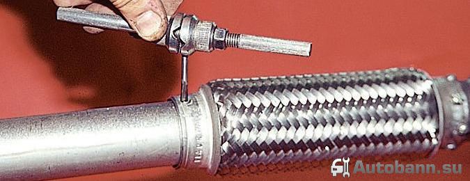
The exhaust system of any car, like other components and mechanisms, is prone to wear. The reason can be various external factors - this is the duration of operation, the manifestation of corrosion, etc. One of the important components of the details is the corrugation of the exhaust system of the car. Despite its durability and strength, it also wears out. Therefore, in order for a do-it-yourself muffler corrugation replacement to be effective, it is necessary to have practical experience in this type of repair work.
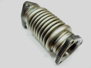
Corrugation (bellows) is an important key element of a modern car, connecting the engine to the muffler. It prevents mechanical deformation of the engine, thereby increasing the performance of the exhaust system.
- Bellows with external and internal braids, which are used only on cars with a gasoline engine. The outer braid of the corrugation prevents strong vibrations, and the inner braid serves as protection against deformations, which can subsequently lead to its breakage;
- Bellows with three braids, suitable for both diesel and gasoline engines. It includes an additional inner braid made of durable tubing.
Bellows (corrugation) - is the most vulnerable part of the exhaust system. Basically, mechanical damage to the device occurs due to uneven sections of the road, contact with stones and other hard objects. Also, its operation is negatively affected by catalyst clogging, improper dismantling of the muffler, excessive stretching, etc.Corrugation bends, where moisture settles, as well as connecting seams, are most often damaged.
Consider one of the correct options for removing the device with your own hands:
- First you need to unscrew the nuts from the manifold and the exhaust pipe;
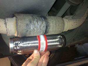
- After removing the front pipe, we proceed to cutting off the old corrugation with the help of a grinder. In the case when the device is under the manifold, it should be cut carefully so as not to damage the flange and the pipe itself. It is advisable to remove the remains of old welding with a chisel.
Do-it-yourself installation technology for a new corrugation:
- First you need to change the muffler rubber, and only after that just install the exhaust pipe in its place. It is important that it is in free float, and not compressed or curved;
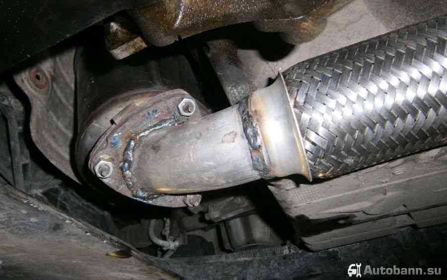
- Having fixed both parts of the receiving pipe, we proceed to install a new corrugation. To do this, we need a welding machine to first grab it in several places, and then scald it at the joints;
- At the final stage, we put the exhaust pipe, together with the rings and gaskets, in place and put on the bracket.
As you can see, the process of replacing a defective corrugation with your own hands is not complicated, the main thing is to follow a simple technology and the result will be obvious. Sometimes situations happen that replacing the muffler corrugation did not bring a positive result. Such cases are very often present in practice and are usually associated with improper operation of other mechanisms of the car - wear of the engine mount, due to strong engine vibration, etc.
To do this, it is better to use the services of specialized auto repair shops with high-precision diagnostic equipment and qualified specialists. With the help of diagnostics, you can detect hidden defects in all components and mechanisms of the car and make repairs quickly and with minimal budget expenditure.
- Ignition systems.
- Fuel supply mechanisms.
- Exhaust gas cleaning unit.
- Engine parameter control unit.
A few remarks should be added to all of the above:
- the release of moisture from the exhaust pipe should not cause any concern - this is normal for modern cars that are equipped with a catalyst;
- the liquid appears due to the formation of condensate, because the outer part of the system cools more intensively than the inner one, this is especially true in winter.
Quite often you can find a situation where moisture appears as a result of a poor-quality replacement of the acoustic filter bellows or its rotten body.
On all machines, even new Mercedes GLS 2016 year, a mixture of gases enters the exhaust manifold from the cylinders, which includes the following components:
- carbon dioxide;
- oxygen;
- water;
- nitrogen oxides;
- carbon monoxide;
- unburned hydrocarbons.
Most often, a similar picture can be observed during the warm-up of the internal combustion engine. The essence of the issue is that the electronics gives the command to enrich the combustible mixture. This is done in order to increase the temperature of the exhaust to heat the same catalyst, because its optimal operation starts around 300°C.
As a result of combustion, a mixture far from the stoichiometric composition contributes to an increase in the concentration of unburned and carbon monoxide gases. It is this fact that leads to the intensive formation of moisture. In this regard, the following points should be taken into account:
- long and active driving effectively removes water from the acoustic filter, which prevents the formation of corrosion on the internal components of the system;
- short trips without preheating, especially in winter, contribute to the accumulation of a large amount of moisture in the noise reduction device, which, when interacting with combustion products, forms an acid harmful to the metal.
Some motorists, when water flows from a car muffler, recommend drilling a hole in its front and rear parts with a diameter of 3-4 mm. In winter, this method will prevent the formation of frost in the catalyst.
An elastic connection to compensate for mechanical vibrations and thermal stresses most often becomes unusable for the following reasons:
- wall damage;
- breaks in the event of an increase in gas pressure in the system due to a breakdown of the catalyst;
- destruction of the motor pillows and fasteners of the exhaust system, which lead to unwanted vibrations;
- external defects of the assembly due to exposure to chemicals that are applied to the roadway in winter.
- Bulgarian;
- heat resistant paint;
- semi-automatic welding unit and related components.
The technological process of replacing the coupling requires the following points:
- using a grinder, cut out the defective part in the places where the braid and the adapter ring are connected;
- cut the rings that are welded on the outer ends;
- eliminate the remains of the weld;
- install a new part in a regular place and weld it;
- treat the welding spots with heat-resistant paint.
After completing the replacement of the corrugation of the car muffler with your own hands, you need to check the tightness of the connections. Gas leakage is determined visually with the engine running. Here are some additional tips to help you get the job done right:
- To facilitate installation, before starting work, it is necessary to mark with a core the joints of the compensator with the pipes of the exhaust system.
- Before installing the corrugations, pre-weld the ends of the double exhaust pipes.
- If there is not enough space for high-quality welding work, then repairs must be carried out on a dismantled exhaust unit.
The reason for the appearance of moisture is condensation processes during temperature changes. This factor is most intense when the engine warms up and disappears after a long drive. For most modern cars, the symptom indicates the correct operation of the catalyst and motor.
If defects in the vibration isolating coupling are found, the reasons that caused its damage should be determined. To carry out repairs, it is enough to have a semi-automatic welding machine and a grinder. The technology of the process consists of cutting off a defective part and welding a new one, followed by processing the seams with heat-resistant paint.
The bellows is the most reliable sealing element of movable joints relative to the external environment (see Fig. 19), which provides almost complete tightness and eliminates stem leakage.
Bellows are made from thin-walled pipes by plastic deformation of the metal. In the fittings of nuclear power plants, bellows made of corrosion-resistant steel 08X18H10T are used.
Single-layer steel bellows according to GOST 17210-71 are manufactured with a wall thickness of 0.08 to 0.25 mm and an outer diameter of 8.5 to 125 mm. Multilayer steel bellows in accordance with the industry standard OST 26-07-857-73 can be manufactured with a wall thickness of 0.16; 0.20; 0.25; 0.32 mm and with outer diameter from 22 to 200 mm. The number of layers of multilayer bellows is from 2 to 10.
Single-layer steel bellows according to GOST 17210-71 are manufactured with a wall thickness of 0.08 to 0.25 mm and an outer diameter of 8.5 to 125 mm. Multilayer steel bellows in accordance with the industry standard OST 26-07-857-73 can be manufactured with a wall thickness of 0.16; 0.20; 0.25; 0.32 mm and with outer diameter from 22 to 200 mm. The number of layers of multilayer bellows is from 2 to 10.
The bellows is usually one (upper) end hermetically attached to the cover or pinched between the body and the cover, and the second (lower) end is hermetically connected to the spindle. Thus, the movable cover-spindle interface is sealed, and the bellows work under the action of external pressure.In this case, the spindle must perform only translational movement, and therefore a keyway or flat is provided in the valve spindles, which prevents the spindle from turning around its axis. The most convenient way of joining the bellows is welding with argon arc welding or roller seam using pulsed current. Welding is often carried out "on the mustache" (Fig. 59), in this case two thin annular protrusions are welded, which creates a tight overlap that is easier to cut and then weld when replacing the bellows.
If traces of erosive wear, dents, scuffs, scratches and other defects up to 0.5 mm deep are found on the sealing surface of the seat, the surfaces should be ground in. With a greater depth of defects, it is necessary to restore the sealing surface by surfacing, followed by machining and lapping (Fig. 50, 51).
To ensure high quality welding of sealing surfaces on plates, it is recommended to use the following method: welding on a plate is carried out through a frame (jig) made of copper (Fig. 52), which contributes to the formation of body-shaped surfacing with minimal processing allowances (up to 1 mm). After surfacing, the surface is machined and lapped.
Table 8.9 shows an example of a flow chart for the repair of a bellows valve body.
The most commonly used methods for making bellows. Only seamless pipes or pipes with a longitudinal weld are allowed to use these manufacturing methods.
Elastomeric formation
The tube is inserted into a core containing a rubber cylinder. The axial force acting on the core stretches the rubber cylinder, forming bulges in the pipe. After that, the load is removed from the rubber cylinder, and the bulge is compressed in the axial direction by an external force, forming a corrugation. Corrugations are formed one by one. The pipe is shortened as the corrugations are formed.
Expansion (Core Stretch Method)
Separate corrugations are formed in the pipe by stretching the inner core. The flatness partially minimizes the expansion, the pipe should rotate a little. The process is repeated until the required corrugation height is reached. Each corrugation is later aligned in size by means of special inner and outer rollers.
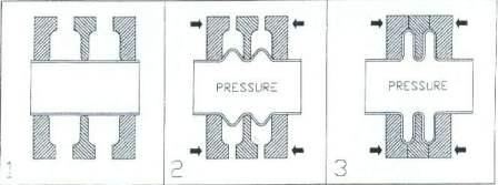
hydraulic forming
The pipe is located in a hydraulic press or bellows machine. Surrounding outer fixed rings are located outside the pipe in the longitudinal direction at intervals approximately equal to the length of the finished corrugation. The pipe is filled with a substance, such as water, and the pressure rises to the yield point. The shaping operation continues with simultaneous peripheral fluidity and is controlled by longitudinal shortening of the tube until the desired configuration is achieved. This method can produce one or several corrugations at once. Depending on the configuration of the bellows, some intermediate steps may be required, such as heat treatment. Balanced bellows can be made using relief rings as part of the fixed plates. When finished, when the fixed plates are removed, the rings become an integral part of the bellows.
Pneumatic formation
This method is identical to the elastomeric formation except for the formation of the initial bulge by squeezing the "inner tube" rubber.
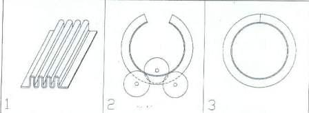
Rolling corrugated sheet
The flat sheet is mechanically corrugated either by pressing or by rollers to obtain straight sections. This preformed sheet is rolled up into a tube. The bellows is obtained by longitudinal welding of the edges of the sheet with each other.
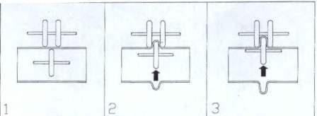
Roll forming
The pipe is located in a bellows machine and one or more corrugations are formed by roller pressure. Usually rollers are located on both sides of the pipe, inside and outside.The pipe may rotate relative to the rollers, or it may be stationary, and the rollers form a bellows by their rotation. The figure shows the first option.
coiled ring
A separate corrugation is made from a flat sheet and then folded into a ring. The edges of the ring are welded across the corrugation. If a bellows with more than one corrugation is needed, the required number of rings are made, which are welded together.
Press forming
A corrugation is formed from a flat sheet using a stationary press. This method is used primarily for the production of rectangular bellows. Using this method, different corrugation profiles can be obtained. The most commonly used U and V-shaped profiles. The possibility of material and method limit the length of the profile. Longer lengths can be obtained by welding several profiles together.
Combined method
| Video (click to play). |
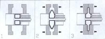
Some of the methods described in the previous paragraphs can be combined. One procedure for forming a toroidal bellows combines two methods. For example, a corrugation is formed by stretching and a height greater than the calculated height. Then, the corrugation is placed between the mold rings, as in hydraulic forming. The rings are compressed and hydraulically formed into a toroid as shown in the figure.

