In detail: do-it-yourself repair of a satellite converter from a real master for the site my.housecope.com.
Repair of a satellite convector at home using scrap materials. After a yearly inspection of your satellite dish, you accidentally discovered a defect on one of the convectors. Do not panic and run straight to the store and buy a new convector. The new satellite converter is not always better than the old one. And the LNB converter for several receiver outputs is much more expensive. Why do you need extra cash expenses?
Quite often, a problem occurs when a crack appears on the protective cap of satellite convectors. As a result, moisture gets into the inner part of the LNB. All these factors are constantly influenced by weather conditions - sun, frost, rain, snow.
Most often, the problem is detected when there is no longer a signal or a bad signal from your favorite TV channel. But this does not always indicate a breakdown. Such converters work for a long time and are used for high-quality repairs.
If you find a converter with a cracked protective cap.
First of all, you need to look inside for water, rust, oxidation. If there is, then we remove the convector and remove the defects. In this case, do not touch the receiving pins of the waveguide. To make it easier to remove the protective cap, we lower the converter with a lid for several minutes in hot water. Your main task is to choose a protective cap for the satellite converter instead of the cracked one. Some craftsmen put plastic bags in several layers on the antenna and wrap them with tape, elastic band or electrical tape. I do not think that such a renovation will last for a long time, but nevertheless it has the right to be.
| Video (click to play). |
The repair will be of better quality if you use an electric soldering iron. For small cracks, it is fine. We solder the crack with a plastic patch. The main thing is that plastic does not reduce the quality of the receiving LNB signal.
Very well, instead of a protective cap, different types of lids from home chemicals (deodorant, shoe polish) are suitable. You can pick up something that fits snugly instead of our protective cap.
Plastic bottles are also great. Cut off the desired length from the bottom, put it on the converter and fill it with epoxy resin or silicone sealant. The quality of such a cap is much higher and it works for a longer time.
Hello, dear readers of the blog Man in the House.Ru. In today's article, as you probably already understood, we will consider the most common causes of a malfunction in the operation of a satellite dish and how to eliminate them.
It is no secret that repair of satellite dishes can be done by hand. Calling a specialist for a tincture can be unreasonably expensive for you. To save the family budget, let's take a look at how to repair a satellite system with our own hands.
Often, after repairs, cable problems arise. The antenna cable, through which the "head" of the satellite dish is connected to the receiver, can simply be interrupted or short-circuited after the next repair. There are also cases where the coaxial cable breaks along the line of the central core. To accurately determine the reason for the failure of satellite television reception, first, check the condition of the cable. Often, a visual inspection is sufficient to detect obvious breaches in the sheath insulation, fractures and pinches in the cable.
You can more accurately determine the condition of the cable by armed with a special device - a digital multimeter. If you don't have such a device at home, then a low-voltage incandescent light bulb from a flashlight and a mobile phone battery will be enough.Such a simple folk device for checking electrical circuits is popularly nicknamed "arkashka". To check with the "arch", you need to connect the tested core to a rupture of the simplest electrical circuit with a battery and a light bulb. If the light comes on, the conductor is intact, and if not, there is an open circuit. Checking a coaxial cable both with the help of a digital device and with the help of a popular notion of the "arkashka" type is simple: we check the central copper core and braid one by one.
A working cable should normally call back between the beginnings and ends of the conductors of the same name, but not between the opposite ones. Simply put, the central core at the beginning and at the end of the wire should normally ring with the device (the "arch" lamp will light up), as well as the beginnings and ends of the braids. It is important to take into account that the device should not ring between the braid and the core (the light will not light up). The resistance between these elements should be high - a few mΩ. A low resistance between the aluminum braid and the copper core of the coaxial cable indicates a short circuit.
Situations are also possible when it is not possible to check the integrity of the conductors of the cable conductors in this way due to the remoteness of the plate and the receiver. It is for this case that the following diagnostic technique can be recommended: firstly, we check if there is a short circuit between the central core and the screen, and secondly, we deliberately short-circuit the core with braided shielding on one side, and on the other, we check with the device. If the device beeps or the "arch" lights up, it means that both the braid line and the core line are completely intact.
The most commonplace option for a short circuit in a cable is improper termination of cables and incorrect connection of f-connectors. It's no secret that novice satellite dish installers strive to install this very dish as soon as possible, not giving a damn about the reliability and quality. Their main goal is to get the coveted 500 rubles as soon as possible.
To prevent a short circuit, which can cause damage to both the receiver and the LNB, it is necessary to carefully check the correctness of the termination of the cable. There is no special trick in this process: you need to carefully strip the top insulation by 1.5-2 cm, remove the silver screen back, strip the central gold vein and screw on the f-connector. Then all that remains is to trim the central copper core so that it protrudes no more than 2-3 mm from the f-connector.
The main mistake newbies make is that they don't pull the hairs of the aluminum braid shield back well enough. These very hairs can eventually come into contact with the central copper core and disable expensive equipment. In fact, a short circuit will occur, which in the worst case will "kill" the receiver. It is also a mistake to cut off the aluminum foil. It is better to simply slide it back so that the f-connector better connects and holds on to the coaxial cable. In any case, it is necessary to carefully check whether there is no short circuit between the center conductor and the "ground" of the shield braid. After energizing the receiver, it will be simply impossible to fix anything.
LNB head failures are also very common. Hit of atmospheric precipitation, short circuit, as well as overvoltage - these are the main reasons for the failure of satellite dish converters. To check the breakdown of a specific LNB, simply unplug the discs (if you, of course, have several converters) and connect the heads one by one directly to the receiver. In this simple way, you can quite accurately determine the faulty converter.
Hello.
This is the second time I have lost my Sirius signal.
After replacing the head, the last time, the signal was about 3 hours, then it disappeared.
I changed the connection port 1, with the Sirius cable to Hotbird. Hotbird works, but Sirius does not.It turns out desex + cable + port 1 of the hotbird signal passes, and port 1 + the same cable + head of the working signal NO. Astra and Hetbird are working. What could it be.
Vladimir
Eh, dear Vladimir! Do you know how many disks were made to me to change. I have ten satellites and normally none of them have a signal. Is there a standing master in Pyatigorsk? Give his number, please. Thank you in advance!
Hello. After filing 360 V, the tuner burned out. We bought another, wanted to invite a tuner. However, they admit that everything burned out. Is it possible to check the performance of the heads and other equipment ourselves?
Hello, I have such a problem. There are plates for two TVs. When I turn on one tuner, a signal appears on another TV and it is on the satellite that I turn on on the first tuner. There is no signal on other satellites And so on each satellite .. when I turn off the first tuner on the second tuner, it shows no signal. . When I change Two disks, everything works fine. But not for long for half a year. And then the same situation is repeated again. Tuner OPENBOX X-820BL. What can it be, please tell me. Thank you
Newbie
Group: Users
Posts: 22
Registration: 12/21/2009
User #: 11955
Thank you said: 0 times
Is it in our time?
At a cost of 2 bucks?
p.s. The head is an LNA, a complex microwave device.
Repair requires knowledge, skill and expensive devices.
=============================================
New LNBs are miniature, the body is filled with a compound.
It was possible to repair the old type heads. Everything is on screws, and the board is 3 times larger.
Here is the LNB Cambridge board
We have a General Satellite GSLF-52E LNBF linear polarization converter with two outputs (for two tuners / TV sets). Symptoms: at one of the two outputs it does not catch the vertical polarization channels.
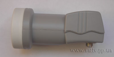
Appearance before raskurochivanie
We remove the plastic case (the most difficult thing is to pull off the cap in front, so that it does not bend and stretch all the edges with a screwdriver). We have:
These rings in front are called "feed", but in fact it is a hood (in photo-terminology), which does not allow rays of an unselected direction to penetrate inside. Next comes the pipe - this is a "waveguide", at the bottom of which there are two mutually perpendicular pins 1 cm long - horizontal and vertical antennas (and a large crossbar behind one of the pins is a reflector of horizontal polarization):
The actual "converter" is an electronic board inside a box sealed with brown rubber sealant. This carpetter converts the carrier frequency of 10700-12750 MHz, on which the satellite emits, to a frequency of 950 to 2150 MHz, which can be driven over regular television coaxial cable. The fact is that a signal at a frequency of about 12 GHz will completely fade in such a cable after 1 meter of its length, and 2 GHz will fade out after 100 meters. Therefore, for the sake of using conventional television cables, this electronics is fenced in the focus of a satellite dish.
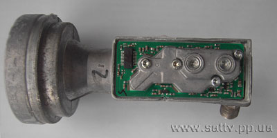
We open the box by cutting off the rubber sealant. On the one side:
Unscrew 3 screws (do not touch the central one) of the screen, we have:
Simple repair of the satellite converter with disassembly.
In this lesson, the voltage stabilizer on the head (convector) is out of order.
Now let's see what's inside the satellite converter for 2 outputs SLWI 52E. In order to see what it consists of, let's take it apart.
Now we are dismantling the circular polarization GSLF-51ER for one output. Let's see what is interesting in it and how it looks inside. We will disassemble this product as it turns out, if necessary, by the method of destruction.
DIY satellite receiver repair. No signal. Does not turn on. Do-it-yourself tuner repair. The most common problems. Using the Orton 4100 tuner as an example, I will tell you how to repair satellite receivers, I will consider almost all the most common problems, I will give practical advice on repair. Help channel qiwi wallet 380939291223,
Does the tree interfere with satellite signal reception? It often happens that a tall tree grows in the direction of the satellite or a house is located.
If you are faced with the task of receiving signals of circular polarization on a linear converter, but there is no circular one, then we install a depolarizing plate in the waveguide of the converter ourselves. Also, the plate must be rotated 90 ° if the circular converter is installed on a toroidal antenna.
We have a General Satellite GSLF-52E LNBF linear polarization converter with two outputs (for two tuners / TVs). Symptoms: at one of the two outputs it does not catch the vertical polarization channels.
Appearance before raskurochivanie
We remove the plastic case (the most difficult thing is to pull off the cap in front, so that it does not bend and stretch all the edges with a screwdriver). We have:
These rings in front are called "feed", but in fact it is a lens hood (in photo terminology), which does not allow rays of an unselected direction to penetrate inside. Next comes the pipe - this is a "waveguide", at the bottom of which there are two mutually perpendicular pins 1 cm long - horizontal and vertical antennas (and a large crossbar behind one of the pins is a reflector of horizontal polarization):
The actual "converter" is an electronic board inside a box sealed with brown rubber sealant. This carpetter converts the carrier frequency of 10700-12750 MHz, on which the satellite emits, to a frequency of 950 to 2150 MHz, which can be driven over regular television coaxial cable. The fact is that the signal at a frequency of about 12 GHz will completely fade in such a cable after 1 meter of its length, and 2 GHz will fade out after 100 meters. Therefore, for the sake of using conventional television cables, this electronics is fenced in the focus of a satellite dish.
We open the box by cutting off the rubber sealant. On the one side:
Unscrew 3 screws (do not touch the central one) of the screen, we have:
Satellite converter (LNB, Low Noise Block) is a device that is designed to receive a satellite signal, convert it and transmit it via cable to a satellite receiver (receiver). The Ku-band converter for an offset antenna is structurally made in the form of a monoblock, i.e. irradiator, waveguide, electronic board are connected into one whole.
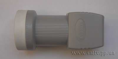
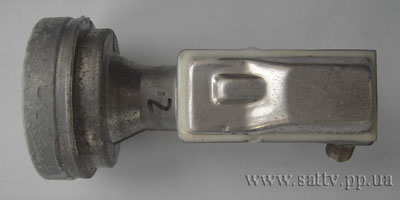
Converter without plastic housing.
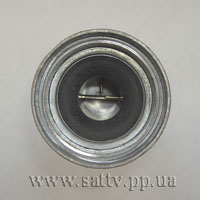
Under the plastic housing there is an aluminum feed, a waveguide and a housing for an electronic board. Structurally, this is all combined into a single whole. The metal cover that covers the board is sealed with elastic sealant along the edges to protect the electronics from moisture. After removing the top cover, we see the printed circuit board and the metal structure on it.
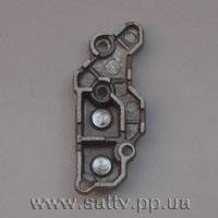
This is a screen for the microwave path. It also houses chambers for two resonant local oscillator resonators (one with a frequency of 9.75 GHz and the other with a frequency of 10.6 GHz) with adjusting screws. Tightening the screw changes the volume of the chamber and, as a consequence, the frequency of the local oscillator, which makes it possible to shift the intermediate frequency of the signal at the output of the converter within a small range.
The block diagram of a universal Ku-band satellite converter with one output is shown in the figure:
The universal converter has two receiving pins located at 90 degrees relative to each other (for horizontal and vertical polarization). The signal from the receiving pin goes to the first amplifier stage, then to the buffer amplifier, from the output of which it goes to the mixer. The mixer is also fed a signal from one of the generators (10.6 GHz or 9.75 GHz, depending on which band is selected), as a result of which the frequency of the received signal is reduced to the range of 950 - 2150 MHz. After the mixer, the signal is fed to the last amplifier - the intermediate frequency amplifier (IF). The switching of polarizations and local oscillators is performed by the control controller.
Frequency conversion in a satellite converter is based on the principle of operation of a heterodyne receiver and is as follows.If we take two harmonic oscillations with different frequencies (cos (ω1) and cos (ω2)) and add them, the result is the sum of two harmonic oscillations with a frequency cos (ω1 + ω2) and cos (ω1 - ω2)... This follows from the trigonometric formula for the product of cosines
For example, if the frequency of the received signal from the satellite is 11900 MHz, then when it is added to the local oscillator signal with a frequency of 10600 MHz, we will receive signals at the output of the mixer with a frequency of 11900 - 10600 = 1300 MHz and 11900 + 10600 = 22500 MHz. The 22500 MHz signal is filtered in the IF amplifier (since it has a bandwidth of up to 3 GHz), which is located behind the mixer. As a result, only a signal with a frequency of 1300 MHz will remain, which will be transmitted to the satellite receiver via cable.
Let's take a closer look at the printed circuit board of the converter:
Where can I use parts from the converter.
The satellite converter uses parts (transistors, amplifiers) with fairly good parameters. Transistors with similar characteristics are not always available in radio stores, and if they are, then the price for them is usually high. The cost of the cheapest satellite converter is about $ 1.5-2. For this money, you get 2 gallium arsenide transistors, 3 HF bipolar devices and 2 HF field switches (not counting the broadband amplifier and strapping from SMD resistors and capacitors). I used 2SC5508 transistors in a 430 MHz radio beacon. The BGA2712 chip with NE3503M04 can be used in an antenna amplifier in the decimeter range. For better amplification, you can leave the native PCB by removing the local oscillators and the horizontal polarization channel (so that you can power the amplifier from a 12V power supply, since 18 Volts must be applied to turn on the horizontal polarization receiving channel). In this case, the signal from the antenna must be fed to the receiving pin, and removed from the output of the converter. Forum radio amateurs> have successfully converted a satellite converter into a 10-12 GHz transmitter.
List of literature on this topic
2. Koryakin-Chernyak S. L. Handbook for the repair and adjustment of satellite equipment 2010.
The device and circuitry of the satellite receiving kit. Part 4 - Converter
Written by Administrator on March 22, 2012. Posted in Do it yourself


The photos below refer to my design of the converter holder, as, in some designs satellite dishes, there is no adjustment described below at all, but usually similar designs work on the same principle. And the main thing is not this, but what would convey to you, for the future, the basic principle of this setting.
Converter holder on my satellite dish, fastened with one bolt and nut. If we loosen them, then this holder, together with the converter itself, can be brought closer or further away from the spherical mirror. satellite dishmoving them in a certain plane (Photo 1).
To make this possible, the manufacturer made a longitudinal hole in the pipe itself, on which the satellite converter holder is attached (Photo 2).
Why do we need to adjust the distance between the converter feed and the reflecting surface of the mirror? satellite dish?
Here the point is that, focused by the mirror satellite dish the beam must fall into the center of the converter feed. When you put the converter itself on the L-shaped holder, the reflected and focused signal beam can only hit the edge of the feed. For example, on the upper edge of the irradiator (Photo 3), well, or on the bottom (Photo 4).
So we must make the adjustment so that the signal hits exactly the center of the irradiator. But since we cannot see the signal itself, we will do this setting, again, by the indicator of the level and quality of the signal of the satellite receiver. That is, according to its maximum indicator.
To begin with, remember on the indicator itself, the percentage level of the satellite signal.We will do this in order, since during the converter setup, we will cover with our hands a part of the signal flow itself. Move the converter, for example, towards the mirror satellite dish, in small steps until it stops. From time to time, removing your hands from the converter, look at the signal level. Do the same by sliding the converter to the other side.
In general, find the position of the satellite converter in which the signal indicator of your receiver will be as maximum as possible.
To focus the satellite signal on the converter feed, loosen the screws that fix the converter itself to its holder. Loosen so that it can move back and forth with a little effort (Photo 1).
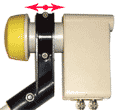
Photo 1
You, the design of the converter holder, may be different, but the principle of all settings will be the same, the same.
The focus adjustment process is the same as for centering, which I described above. Also remember the percentage signal level on the indicator. Move the converter, first in one direction, in small steps until it stops (Photo 2), do not forget to remove your hands from the converter body and look at the signal level. Do the same by moving the converter to the other side (Photo 3). And thus, find the position in which the signal will also be maximum.
After bringing the converter into focus, and tightening the fastening bolt and nut, you can proceed to another setting of the satellite converter. This will be the last stage of the mechanical satellite dish settings.
Here we need to adjust the vertical position of the satellite converter. The process of this adjustment, again, such as when centering and adjusting focus, which I talked about on the previous page, the only difference is that we will carry out this adjustment in a different plane.
Take hold of the converter body and rotate it on the holder into one. and then in the other direction (Photo 1), while being careful not to knock out the focus setting. Maximize the reading on the signal strength meter. After adjusting, tighten the mounting screws.
Do not despair and run straight to the store. After all, not always a new converter is better than an old one. And converters for multiple outputs are also more expensive. Why do you need extra expenses?
So, quite often the problem occurs when the covers of satellite converters crack. And all because of not very high quality materials and the constant influence of the sun, frost - weather conditions.
Most often, the problem is detected when there is no longer a signal. But this does not always indicate a breakdown. Such converters work for a long time and are used for high-quality repairs.
First of all, you need to look inside if there is any rust or oxidation. If there is, we carefully remove it, do not touch the receiving pins.
To make it easier to remove the lid - lower the converter with the lid for a few minutes in hot water.


Our main task is to pick up the cap for the satellite converter instead of the broken one.
Some craftsmen put plastic bags in several layers right on the antenna and grab them with tape, elastic band or electrical tape. I do not think that such a renovation will last for a long time, but nevertheless it has the right to be.
The repair will be of better quality if you use a soldering iron. With small cracks, it will come off. We close it up, if necessary we put a patch of plastic. The main thing is that the material does not reduce the quality of the receiving signal.
Different types of corks from home chemistry (deodorant, shoe polish) are suitable instead of caps. You can pick up something that fits tightly instead of our cap.
Plastic bottles are also great. Cut off the desired length from the bottom, put it on the converter and seat it. Easily done with a technical hairdryer, you can try it over a gas stove.


The quality of such a cap is much better than the bags and has been working for a long time.
Moreover, it is always possible to use a sealant.
Posted by admin in Household appliances 07.06.2018 0 38 Views
There are a lot of satellite antennas, they are divided in everyday life into two global types, offset and direct focus. The difference is in the arrangement of the converter feeds. If just in the center, we have a direct focus satellite dish. Beginners are wondering why cymbals are so different from other receiving devices that surround humanity in everyday life. It's about directed properties. Dishes (parabolic antennas) have a large gain and a narrow radiation pattern. Rigid stabilization of the satellite in orbit is required, but the radiation power can be significantly reduced. The spacecraft received from the developers a wide radiation pattern, covering thousands and millions of square kilometers of the territory. 99.99% of energy is wasted. Repairing satellite dishes with your own hands is more about tuning, positioning, and the correct use of converters.
The main types of failures relate to converters. The plate can only be damaged on purpose. Indeed, why break a piece of iron. Making a satellite dish is ridiculously simple:
- a plate is suspended on a bracket to the wall;
- feeds are placed in the focal plane of the paraboloid.
Everything! A signal comes from the satellite, the object is far away, it is believed that the lines are parallel. As a result, according to the laws of optics, the signal is collected in the focal plane. For offset antennas, the dish is not perpendicular to the direction to the satellite, the feed is far from the center. On the contrary, with direct focus antennas, the converter is located on the axis, due to which part of the signal is lost. This is an inevitable flaw. For offset antennas, the feed hangs outside the dish, another factor manifests itself: the catching area of the rays is proportional to the cosine of the deviation from the perpendicular. This is not to say that the first design is better or worse than the second.
Offset antennas are useful where there is no chance of tilting the dish so that the axis looks directly at the satellite. These are predominantly equatorial and tropical regions. In practice, offset antennas are not less common than direct focus antennas. It is wrong to call the feed a converter and vice versa. A device hanging near the focal plane of the antenna includes:
- Irradiator. Looks like a tapered opening, protected by a plastic removable casing from precipitation.
- Depolarizer. A section of a straight waveguide (pipe) where a dielectric plate and a pair of rods are located. Serves for converting circular polarization to linear.
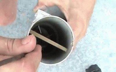
- Converter. It represents an electronic unit where the satellite frequency is reduced to 1 or 2 GHz for transmission over the feeder with the lowest loss. An additional low-noise amplifier is located here. The sensitivity formula is dominated by the characteristics of the first active stage. It is important to reduce the noise level here.
The matter is complicated by the broadcasting of satellites in the frequency range. C and Ku bands accepted. In any, its own kind of polarization dominates. On C - circular, in Ku - linear. Newbies are perplexed. We clarify that the C-band used in the Russian Federation has circular polarization for a number of reasons:
- The legacy of a difficult past. In the USSR, circular polarization was used on spacecraft for satellite transmission of information, the orbit of the spies was different from the geostationary one. It was not required to take into account the angle of inclination of polarization, as when using the horizontal type.
- The polarization vector is deflected by magnetic fields. Solar storms and fluctuations in terrestrial characteristics affect the tilt angle. Moreover, the Faraday effect decreases with increasing frequency. Therefore, in the Ku band it is not too scary.
Such features simplify the setup of the equipment, there is no need to rotate the converter around the axis, which is great - the angle is difficult to catch. If C and Ku are broadcast with linear polarization, the Faraday effect affects differently, as a result, the antenna cannot be tuned in the desired way. This is worse than the loss caused by a hybrid converter. It is difficult to estimate, but the closer the subscriber is to the pole, the stronger the distortion.RF lies in the northern territories.
We add that the Ku and C bands are so large that the sections are split additionally, otherwise it is impossible to design local oscillators to obtain intermediate frequencies (see above). Satellites do not capture the entire spectrum, which is taken into account by converters. Keep advice:
Check in addition to the range of the sub-range of the provider. When choosing equipment, make sure that the converter supports the wave.
The converters are similar in appearance: a steel box, a pipe section, opened, the structure is sewn into plastic, covered with a cover from the side of the entrance. From the point of view of geometric dimensions, there is a difference for the ranges, but the filling is more important. In any case, the electronics have their own bandwidth, without a match, the signal will not pass. Let's say more - the manufacturers keep the equipment stuffing a secret, so some converters work outside the standard limits, this is rather an exception to the rule than a constant pleasant surprise for the user. Hybrid converters work at all frequencies (check), there are two receivers inside.
Any converter, regardless of inclination, looks to the center. This will ensure that the maximum energy hits the opening. If it deviates slightly, it will continue to work worse. With the improvement of work, a situation of superposition of fields is possible, when the rule is violated, but in the general case, center the aperture so that you look at the bottom of the plate. Modern equipment performs satisfactorily in many situations, but key points should not be overlooked.
Setting up a satellite dish begins with orientation. An angle calculator is found on the provider's website or in an accessible place. They are aimed at a specific satellite, or the coordinates of the spacecraft will need to be entered. Of course, you need to know your geographic location as accurately as possible. Easier to find with a smartphone with a navigation module. The accuracy is sufficient for calculations. The calculator will give the elevation angle, azimuth, and tilt angle of the converter. It happens that there are several satellites. Then we look at the coordinates of the spacecraft, find the middle one, aim the saucer at the device.
In the latter case, one feed will be in the middle. For an offset dish, the elevation angle is different from that given by the calculator. Or the robot will ask about the type of antenna. As a rule, offset feeds are slightly shifted downwards, it is worth considering when aiming. They differ from direct focus ones, for example, in the F / D ratio (antenna focal length per diameter). It is possible to distinguish approximately the irradiators by their appearance: the offset horns use a stepped horn, the straight focus concentric circles. This is not a rule, but this is the case in reality. Therefore, when using unsuitable illuminators, do not be surprised that the reception quality is below average.
They made it clear what to do when tuning the antenna yourself. We add that targeting can be done using the receiver. In most sets of satellite dishes, built-in programs (means) for capturing waves are given quality, power. If the first person looks at the screen, and the second person works on the bracket, the result will be achieved by joint efforts.
Using the compass, set the azimuth, the elevation is measured with a level and a protractor. After an approximate installation, positioning begins according to the indications of the equipment. After reaching the maximum, experiments with the angle of inclination of the converter begin.
Then we proceed to the installation of additional irradiators, if any. For a specific one, the angle of inclination is determined separately. If the satellite broadcasts in two bands, you should take a hybrid satellite dish converter. The tilt angle of the depolarizing plate sets the direction of circular polarization. If the setting is incorrect, there is no reception. Without undertaking repair of satellite dishes, it is recommended to remove the plate, pick up the signal without it, and then put it on. It is a challenging process, but doable.In the absence of a plate, the received power is 3 dB lower, which corresponds to an equivalent decrease in the area of the plate by 1.4 times.
Notch the brackets before removing the antenna, this will help to quickly put the dish in place. The main causes of breakdowns relate to the directional failure of the paraboloid. By the way, do not forget to put a lightning rod next to it, otherwise the lightning will burn the converters. The electronic part cannot be repaired. The country has not yet learned how to program microcircuits.
Satellite converter LNB or (low-noise block) is a very important component of the overall project for reliable signal reception.
As you probably know on the dish (satellite dish) there is a satellite converter or converters for different purposes.
Catch a signal from the satellite and process this signal beautifully. In order for a beautiful picture to appear on the TV.
LNB or satellite head is installed on the receiving satellite dish. If you want to watch a movie from many satellites, then the satellite converter will not be one, but several.
And so we have a clarity that converters are designed to convert the received signals, namely, to lower the frequency spectrum, linearly transfer it to a lower frequency region.
The need for such a conversion arises from the fact that the frequencies at which the satellites operate are too high to be transmitted over the cable.
The decoding of the abbreviation LNB ambiguously hints at the main characteristic of the converters and this is the noise level, you probably guessed, the lower the noise, the better.
The noise level of modern converters does not play a big role, since it usually ranges from 0.1 to 0.5 decibels and practically does not affect the signal quality in any way.
This LNB device or satellite converter is mounted on a special holder called an outrigger bracket (included in the satellite dish kit) so that the head is in focus of the antenna mirror.
For broadcasting TV programs from satellite, 2 bands are used. The C-band is the frequency range from 3.4 to 4.2 GHz. Ku-band is a frequency band from 10.7 to 12.75 GHz. The Ku-band is too wide, so it is split into 2 sub-bands: lower (10.7-11.7 GHz) and upper (11.7-12.75 GHz).
The Ku-band converter contains two local oscillators to work with both sub-bands. As a rule, a 10.6 GHz local oscillator is used for the upper sub-band, and 9.75 GHz for the lower one.
LNBs are available in Circle and Universal polarization. There are two types of satellite signal polarization: left-right (circular) and vertical-horizontal (linear).
Different satellite TV operators work with different polarizations. The most common ones are presented below:
Tricolor TV -CIRCULAR
NTV Plus -CIRCULAR
Telecard- UNIVERSAL
Continent TV -UNIVERSAL
Rainbow TV -UNIVERSAL
LNBs differ in the number of independent outputs. There are converters with one (SINGLE), two (TWIN), four (QUAD) and eight (OCTO) outputs. If you buy a converter to watch satellite TV on only one TV, then you need a converter with one output.
If you intend to install the kit on 2 TVs, then the converter, respectively, must be with two outputs. Sometimes, in order not to lead a lot of wires into the apartment, instead of putting, for example, a converter on four outputs, a satellite signal divider is used.
Outwardly, it really looks more aesthetically pleasing and in some cases much more convenient, but one should not forget that when using a divider, you get about 5 decibels of noise into the load, which will negatively affect the signal quality.
But in some cases, you cannot do without a divider when the house has already been finished and wired for on-air television. In this case, it is impossible to do without the divider.
An average converter can last from one to five years depending on environmental factors, mainly the abundance of rainfall and humidity.
There are also cases when, due to a manufacturing defect, the converter breaks down within a couple of weeks from the moment of installation.
But even in this case, it makes no sense to look for the truth, since it is unrealistic to prove that the cause of the breakdown is unrealistic in the quality of the converter assembly, and the warranty for them, as a rule, does not apply.
It is believed that it is easier to buy a new one than to repair it.But this is also not a panacea for everyone. Since we have already started talking about the new converter, here is a novelty for your attention, for confident 4K reception.
The Inverto Essential converter is the ideal solution for satellite broadcasting throughout Europe, allowing you to get the most out of your antenna.
The developers of Inverto Essential have taken care of the 4G / LTE signal filter, so that new generation mobile networks do not interfere with the excellent reception of this converter!
What's relevant, Low Noise Figure, Low Phase Noise, DVB-S2 (HDTV) and 4K Ultra HD Compatible, Low Power Consumption, High Cross-Pole Performance.
• Low phase noise, DVB-S2 (HDTV) compatible
• Ultra Low Noise ULN + technology
• Low power consumption
• High cross-polarization characteristics
• High frequency stability
• Noise figure: 0.3 dB (ULN +) Typ. (0.7dB Max.)
• Input Low Range: 10.70-11.70 GHz
• Input High Range: 11.7-12.75 GHz
• Output Low Range: 950-1950 MHz
• Output High Range: 1100-2150 MHz
• Lower LO frequency: 9.75 GHz
• Upper local oscillator frequency: 10.60 GHz
• Waterproof housing
• Number of outputs: 2
There are not many satellite converter disease syndromes.
And so, during manual search, the receiver shows that the signal strength is more than 50 percent, and the quality is 0 percent. But often the same indicators occur when you are mistakenly tuned in to another satellite.
Or even so ... sometimes the converters "fly out polarization", or only some of the frequencies. At the same time, it does not show some of the channels. The receiver displays the message "No signal" on them.
As a rule, an effective treatment under all circumstances is to replace the defective converter with a new one.
It should be remembered that the new converter must be of the same polarization as the one that was previously out of order.
When installing the satellite converter yourself, be careful not to change the angle of the antenna direction, this will save you from having to re-tune the antenna to the satellite.
Converter functions
Converter for converting microwave frequencies to a lower frequency, called intermediate (900-2150 MHz). The signal at this frequency is transmitted through the cable to the receiver and fed to its antenna input.
To reduce the received frequency spectrum, one or two local oscillators are built into the converter - stabilized high-frequency sources. The input frequency is reduced by subtracting the local oscillator frequency from it.
Converter for amplification of the received signal. After all, the signal from the satellite is received with a very low power, completely unacceptable in the paths of the receiving equipment. Therefore, the second, no less important, function of the converter is amplification.
The 13/18 V signal is used in modern universal converters only for polarization switching.
Versatile converters from other Ku-band full-range converters are distinguished by the versatility of signals that control band switching and polarization, as well as the fact that these signals are transmitted over the same cable with an intermediate frequency.
• Firstly, install two converters on the antenna, each with its own feed and polarizer. But at the same time, the feed of at least one converter will not be completely in the focus of the antenna, which will somewhat reduce the antenna directivity;
• Secondly, purchase a design called a C / Ku-rotor, which includes feeds for the C- and Ku-bands, dividing the received stream into two parts. C / Ku-rotors are produced combined with electromechanical polarizers.
But at the same time, there are tangible losses in the power of Ku-band signals and frequent failure of the moving parts of the electromechanical polarizer, especially at low temperatures;
• third, install a combined converter for receiving C- and Ku-bands, which is still inferior to separate converters in terms of technical characteristics.
Converters must be sealed.Otherwise, due to daily temperature fluctuations, condensation forms inside the converter, which leads to a deterioration in its parameters and, ultimately, to failure.
In addition to insufficient tightness, there are other variants of structural defects, for example, high damage to sunlight or temperature extremes.
We got to the place about my experiment with an offset satellite antenna, read it.
Breakdowns happen, it is quite difficult to insure against such tricks when buying. Here is a video that can help you with head repair:
| Video (click to play). |
In addition, we will consider the subtleties of the setting, specifically the LNB setting, what and why, and most importantly, what I do before the onset of cold weather and also recommend the same thing in the spring.

