In detail: DIY repair of the voltage stabilizer ruself from a real master for the site my.housecope.com.
voltage regulator playlist
something disappointed with the quality in 2 years ((
The resant is no better.
Taking into account the work for which he was not intended and the strong daily loads, everything suited me. He paid for himself a long time ago, and if that is not a pity, and change. Resantu rasiatrival before buying, but the reliability is completely razocheravali and I think she will fly also on the warranty period. In general, it is advisable to install either a triac or transistor even more powerful, but the price bites
With a repair, do not get lost, otherwise it disappeared and is not visible, not audible


+ BI BI RUS will stock up on beer and kirieshkas, and the judge for soap earlier.
))). The national team of Bavaria has left for the training camp, but a new Sonya plestation has been bought))), so the half-bass will be


+ BI BI RUS Gray When football is over, Lewandowski is eager to score goals for Gray.
Like any other electronic equipment, voltage stabilizers are susceptible to damage. Some models have a long service life, others break more often. Much depends not only on the quality of the installation, but also on the thoughtfulness of the circuitry.
The most susceptible to breakdowns are units that contain mechanical devices: a brush assembly in electromechanical stabilizers and electromagnetic relays in relay ones. Failures of thyristor devices are much less common and are mostly associated with abnormal voltage values and low-quality components.
It is impossible to foresee all variants of breakdowns within the scope of one article, and only highly qualified specialists are capable of repairing complex electronic equipment. However, some damage can be repaired at home.
| Video (click to play). |
Further, we will talk about the repair of the Resant stabilizer, as the most common brand. Other types of devices are either clones or have similar circuitry and internal structure.
Any repair to stabilizers should begin with a visual inspection of the interior of the device. First of all, you should pay attention to the absence of visible damage: burning of the tracks on the board, the terminals of the elements, the integrity of the transformer windings. Often breakdowns in the stabilizer occur due to improper operation of the control circuit, which is caused by the loss of capacity of electrolytic capacitors. Such elements usually have a bulged end of the body and must be replaced first. Let them not be the cause of the breakdown at the moment, but next time they will make themselves felt. The capacity of the replaceable capacitors should be the same as on the original, and the operating voltage may exceed the required - there is nothing wrong with that, even better.
Important! When replacing capacitors, do not reverse polarity.
Further search options depend on the type of stabilizer used.
A significant part of the damage to electromechanical devices is associated with critical wear of the servo brushes. The movement of the brushes along the bare part of the windings occurs with significant friction, as a result of the passage of large currents through the brush-winding contact, the elements of the brush assembly are heated. All this leads to the destruction of the brush material. If during inspection it is revealed that the brush is damaged, its wear prevents it from firmly pressing against the winding, then the brushes must be replaced.
Another case of breakdown is the burning of the winding wire and the closure of adjacent turns with electrically conductive dust from the brushes. To restore performance, you need to clean the bare part of the winding from oxides with fine-grained emery paper.
Important! Do not use coarse grain pelt, as the grooves on the surface of the wires will cause strong sparking and burning of the windings and brushes. The main criterion for choosing a grain size is the absence of visible grooves on the surface of the wire.
Dust between the windings can be removed with a strong blast of air from the compressor. Not everyone has such a device, so you can use an old hard-bristled toothbrush. The work will be easier if the brush is moistened with alcohol of the maximum concentration.
Note! Diluted alcohol, solvents, and especially water should not be used.
In relay stabilizers, electromagnetic relays have the least reliability. The flow of large currents through the contacts causes their burning or even sintering. The latter is dangerous in that it can cause a short circuit of part of the autotransformer windings.
Resant voltage stabilizers or similar ones have five relays on the board, which switch parts of the autotransformer windings according to a certain algorithm. The predominant fluctuations in the input voltage of about one value lead to the fact that only part of the relay, one or two, are constantly in operation. Therefore, it is they who, first of all, fail.
The search for a faulty element is made difficult by the fact that small-sized relays are low - and medium-power stabilizers have an opaque non-separable case. Sometimes it is possible to identify a faulty relay by lightly tapping the body of each relay with an insulated screwdriver handle. Under mechanical stress, the resistance between the burnt contacts can be restored, and the sintered contacts can open. Found relays must be changed without fail.
Powerful devices can have a relay in a transparent case, through which the operation of the contact groups is visually observed. In addition, the body is collapsible for cleaning. Burnt contacts can be tidied up with fine-grained emery cloth. The grain size should be even smaller than when cleaning the windings of electromechanical stabilizers.
Relay in transparent housing
In the event that a visual inspection did not reveal any damage, the relay can be removed from the board and the contacts can be ringed using an ohmmeter. The location and numbering of contacts are shown on one side of the relay housing. The device should show infinitely high resistance between normally open contacts, and close to zero between closed contacts. Having applied a constant voltage of 12 V to the control winding, they ring the contacts again. Now those that were open should close and vice versa.
Important! The relays have powerful leads and require the use of a suitable soldering iron for soldering. Do not overheat the printed conductors.
If there is a LATR - laboratory autotransformer, then troubleshooting and repair of the Resant or other device can be greatly simplified. To do this, assemble the simplest chain:
- The LATR input is connected to the power supply;
- LATR output - to the input of the stabilizer;
- An AC voltmeter is connected to the output of the stabilizer.
Rotating the LATRA adjustment knob from minimum to maximum values, observe the operation of the stabilizer and the voltmeter readings. In a mechanical stabilizer, when the input voltage changes, the servo shaft with the brush assembly should rotate, and the output voltage should correspond to the rated voltage.
In relay stabilizers, you can hear the switching on of various relays, and the output voltage will change stepwise with a swing of no more than 10V when the input voltage changes from the minimum to the maximum.
This repair of the voltage stabilizer is more complicated and requires knowledge of the operation of electronic circuits. In relay and thyristor stabilizers, key transistors that control the operation of triacs or relays are subject to verification. The transistors are checked according to the usual method after they have been soldered from the board. The resistance between collector and emitter must be infinite for any polarity of measurement.
Resistance base - collector and base - emitter in one polarity should also be infinitely large, and in the other - be insignificant.
In electromechanical stabilizers, you can observe the lack of rotation of the servo shaft when the input voltage changes. The reason for this is a malfunction of the HA17324a operational amplifier. This IC has a low cost and is widely available on the market.
Repair of the voltage stabilizer in some cases is possible with your own hands with a minimum of time. It should be borne in mind that the safety of family members may depend on the correctness of the repair. If you are not completely confident in your abilities, then it is better to entrust this matter to a professional.
Today we will consider a list of basic malfunctions of voltage stabilizers of various types with a description of the causes of occurrence and methods of their repair.
Today we will consider a list of basic malfunctions of voltage stabilizers of various types with a description of the causes of occurrence and methods of their repair. After all, not every breakdown of a voltage stabilizer requires service repair, especially after the expiration of the warranty period.
About the internal structure and types of stabilizers
Of all the varieties of voltage stabilizers, three most common topologies can be distinguished with rather specific conversion principles. Among them, it is impossible to single out the most reliable one, too much depends on the nature of the power supply and the type of load, as well as on the quality factor of the device. In our review, we will consider servo, relay and semiconductor converters, features of their operation and typical malfunctions.
In a servo-driven stabilizer, the main functional element is a linear transformer with a multitude of mid-point leads of the secondary, and sometimes the primary winding - from 10 to 40, depending on the accuracy class. The ends of the leads are assembled into a collector comb, along which the collector carriage moves. Depending on the effective voltage on the power line, the stabilizer corrects the position of the carriage, thereby adjusting the number of involved turns and, accordingly, the transformation ratio. At the output of the circuit, a more fine adjustment of the voltage can be carried out, for example, using integrated semiconductor stabilizers.
Relay transformers are designed in a similar way. The number of transformer terminals is smaller; instead of smooth regulation, the fine tuning is achieved by recombination of the windings included in the operation. Power relays with a complex configuration of a relay group are responsible for operational switching. As in the previous case, there may be additional filters, stabilizers and protection devices at the output, however, the main work is performed by a transformer and relay assembly under analog control.
Electronic voltage stabilizers can be based on two conversion principles. The first is switching the transformer windings, but with the help of symmetrical thyristors, and not relays. The second principle is the conversion of current into direct current, its accumulation in buffer capacitors (capacitors), and then the reverse conversion into a “change” with a pure sine wave by means of a built-in generator. At first glance, the scheme seems to be rather complicated, but it provides an unprecedented high stabilization accuracy and high-quality line protection.
Of course, there are other stabilizer schemes, including hybrid ones, but due to their highly specialized use or archaic nature, we will not consider them. Each of the three most common families has so-called childhood illnesses or congenital deficiencies in technology. And therefore, the most important task before sending the device to the service center is to establish whether the breakdown is the cause of non-compliance with the maintenance standards or an ordinary malfunction for this type of stabilizer.
Typical faults of relay devices
Relay stabilizers are characterized by an optimal ratio of cost and reliability. The relay group is exposed to the main wear, and with frequent or constant operation in the mode of increased load - also the dielectric insulation of the transformer windings.
It is quite easy to diagnose a relay as the cause of a malfunction. The first step is to dismantle the components from the printed circuit board; they can be distinguished by a compact rectangular case, sometimes made of transparent plastic, with at least six pins. To determine the purpose of the terminals and the switching scheme, you can refer to the circuit diagram or technical specification for a specific type of relay according to the marking on the case.
You can make a test switching on of the relay, for which the operating voltage is applied to the contacts of the coil, as a rule, it is indicated on the case of the product. The absence of a click when connecting is a clear sign of a burnt coil or stuck contacts. If a click is heard, but when the group of the main contacts is ringing, the circuit of their switching is not observed, the problem is most likely in the mechanism of rejection and pressing, or in charred contact pads.
A significant part of electronic relays has a collapsible housing and can be serviced: restoration of the mechanism, cleaning the contact pads from carbon deposits with an eraser, sometimes even replacing a faulty coil. However, the best solution would still be to purchase new relays to replace the failed ones according to the article number or the location of the terminals.
The loss of dielectric strength of the transformer due to overheating is accompanied by interturn short circuits and is externally observed as darkening or destruction of the winding insulation. The main feature is a significant decrease in resistance below the passport standards.
Since most budget stabilizers have one solid primary winding and a multi-pin secondary, rewinding is not particularly difficult. In each link, the number of turns is small, they can be neatly laid even without a spindle or other winding devices. The most important thing is to accurately observe the number of turns and the direction of laying, as well as to correctly determine the initial resistivity of the conductors, and not just purchase a winding wire by diameter.
Another type of transformer malfunction is the operation of a semiconductor thermal fuse, which is usually included in the rupture of one of the windings. To replace a semiconductor element, it is enough to clarify its series or basic parameters in order to select an analogue. Usually, the thermal fuse is connected in series with the first link of the secondary winding, so all outer turns will have to be removed to access it. The problem is diagnosed simply: between the beginning of the winding and the first tap, the circuit does not ring, but all the other turns are in perfect order.
Broken servo stabilizers
The main reason for failure of servo drives is obvious: wear of the collector assembly. It is this shortcoming that is included in the category of childhood diseases that cannot be eliminated in most models of budget technology.
There are two types of slip mechanisms. At low loads, conventional spring-loaded brushes do an excellent job of switching the windings.The device completely repeats the principle of operation of the collector motors of the power tool, except that the collector itself is deployed from a cylindrical position to a plane. The second type of current collectors has a brush assembly in the form of a roller, due to which friction during movement is reduced, which means that there is no intensive wear of the lamellas. At the same time, the wear rate of tile and roller brushes is approximately comparable.
The disadvantage of a slip ring stems from its geometry. The contact spot is very small - only the line of contact of the cylindrical roller to the plane. True, in the most technically advanced models, the lamellae have radius grooves, although this solution is not entirely justified: as the graphite roller wears out, the contact area inevitably decreases. Depending on the intensity of use, replacement of brushes is required at intervals of 3 to 7 years. The situation can be aggravated in the presence of a large amount of dust and carbon deposits - up to the short circuit of several windings or a complete loss of contact.
Although servo regulators are also susceptible to overload operation, their transformer will wear less. Unlike relay devices, in which voltage and current surges occur regularly during switching, the collector unit adjusts more smoothly, due to which the mechanical effect of the current is minimal. The varnish insulation of the windings still dries up and becomes brittle, but it does not crumble.
Basically, the principle of operation of the servo stabilizer is extremely transparent. If, when turned on, there is an indication of the input voltage, but the device does not respond, the fault lies either in the drive itself or in the control and measuring circuit. In the latter case, a faulty circuit element can be easily detected purely visually or by dialing. If there is no voltage at the output, the transformer is faulty, but if the proper stabilization accuracy is not ensured, the presence of an interturn short circuit in the secondary winding, collector contamination, wear of the collector brushes or the lamellas themselves are evident.
Common problems of electronic devices
Inverter stabilizers are considered the least maintainable at home. There are several reasons for this, but the primary one is the need for special knowledge in circuitry and, in particular, the principles of operation of switching power supplies. It will not be possible to do without an appropriate material base: soldering equipment with temperature control, as well as measuring instruments. The set of diagnostic tools goes far beyond the limits of a conventional multimeter, you will need a device with an extended set of functions for measuring capacitance, frequency and inductance, and it is also desirable to have a simple oscilloscope at your disposal.
The most common cause of failures in the operation of inverter stabilizers can be called a violation in the operation of the clock generator. It is necessary, based on the rated power of the device and the parameters of the transformer, to determine the optimal operating frequency of the pulse converter, and then compare it with the real parameters. Frequency failure is usually the result of a malfunction in the reference oscillating circuit connected to the corresponding pins of the clock IC.
A complete failure of the device is possible for a number of reasons. If there is no built-in diagnostic system, or it is impossible to determine the breakdown by its indications, most likely the cause of the malfunction was the failure of the field or IGBT keys, which is quite simple to determine by the appearance of the case. Another typical cause of malfunctions is a breakdown of the built-in power supply of the control circuits; this part of the circuit is most vulnerable to voltage fluctuations, especially impulse ones.
It will not be superfluous to make a continuity of all circuits, their conductivity must correspond to the circuit and electrical diagrams of the device. The most vulnerable elements include input and output rectifiers, transformer snubber circuits (for suppressing surges), as well as a power factor corrector, if any.
General recommendations
Electronic components are found not only in inverter stabilizers, they can be used in control and measuring circuits or indication and self-diagnosis devices. This mainly concerns passive elements and microcircuits with a low degree of integration: operational amplifiers, logic elements, combined transistors, current and voltage stabilizers.
Failure of these elements can most often be determined purely by external signs: burnt out transistors and diodes have a cracked case, resistors - traces of burned varnish, capacitors simply inflate. Therefore, a close external examination of the printed circuit board is the first step in determining the malfunction.
If it is not possible to visually determine the cause of the breakdown, a sequence of control measurements should be made. First, the conductivity and quality of the dielectric insulation of the circuit is checked in the off state. After that, when power is applied, voltages are measured at key points: at the connection terminals, after the fuse, on filters and stabilizers, transformer windings, and the main nodes of the control circuit.
If the described diagnostic methods do not give a result, it is better to contact a service center, because even a simple breakdown can be very specific, despite the fact that amateur knowledge in electrical engineering and home conditions is not enough to eliminate it. published by my.housecope.com/wp-content/uploads/ext/941
If you have any questions on this topic, ask the specialists and readers of our project here.
Consider a way to self-repair the Ruself voltage stabilizer model SDW-10000-D, with a defect there is no stabilization and no output voltage.
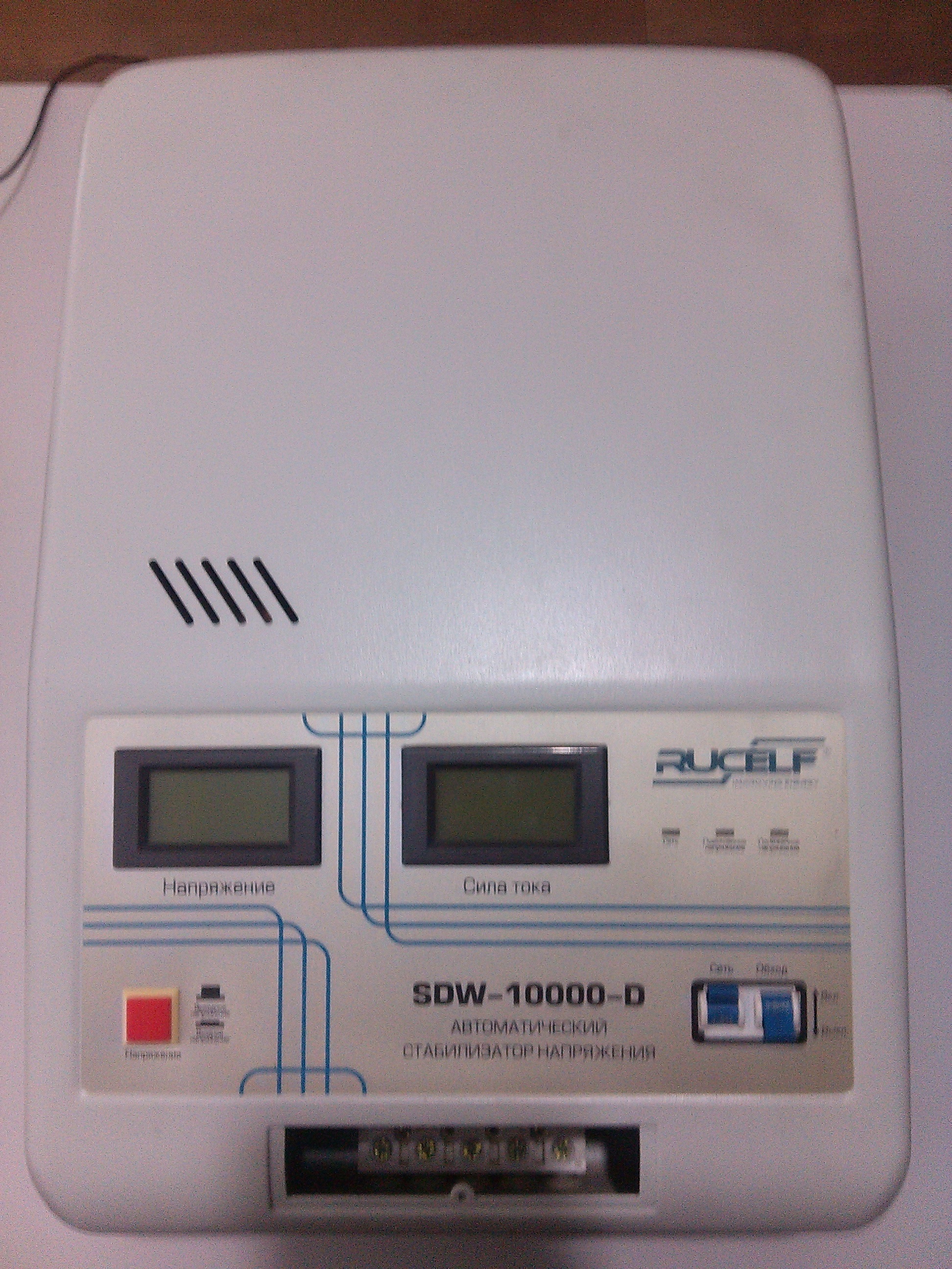
Take a screwdriver and unscrew the bolts on the sides of the stabilizer and remove the top cover.
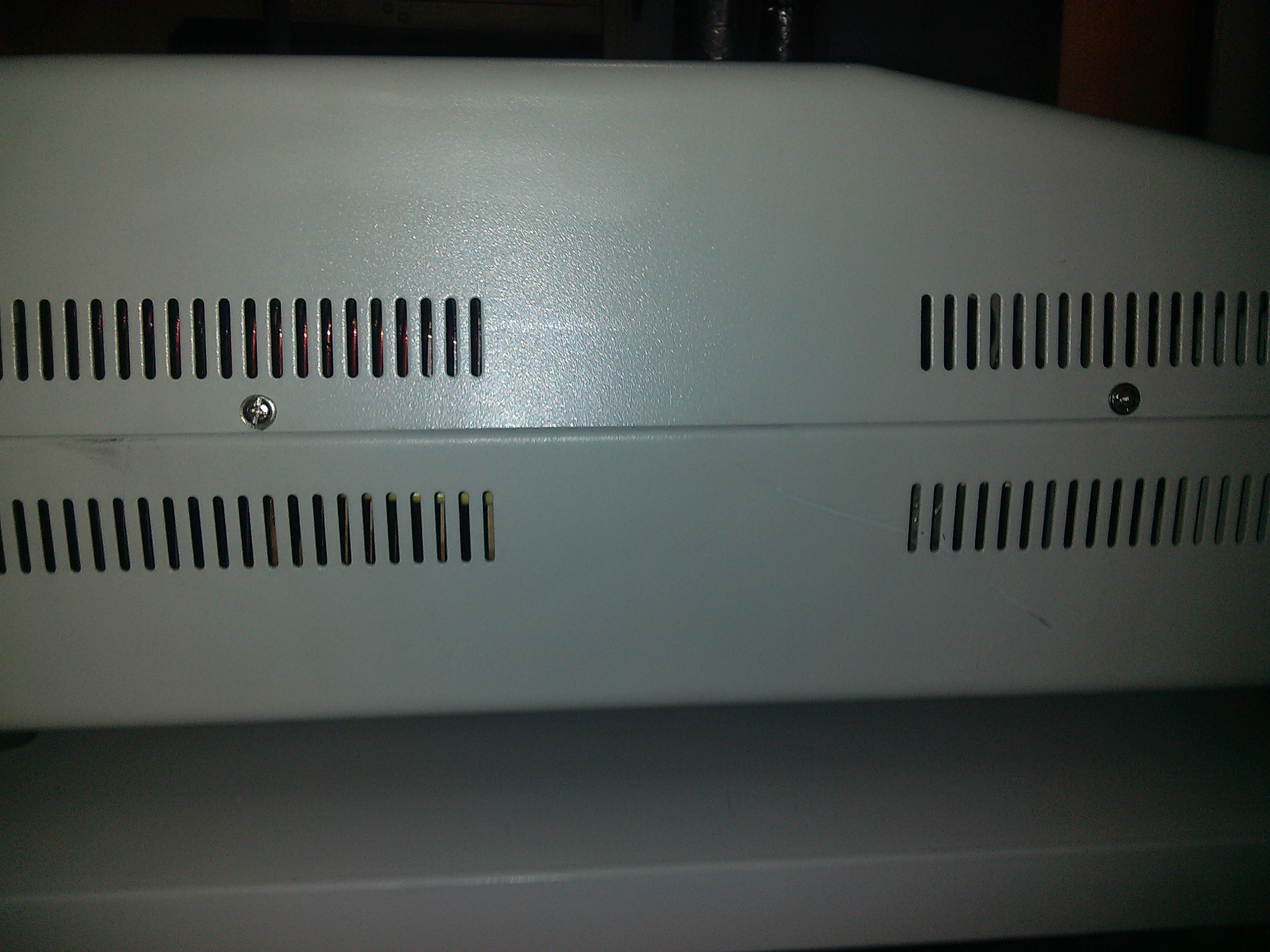
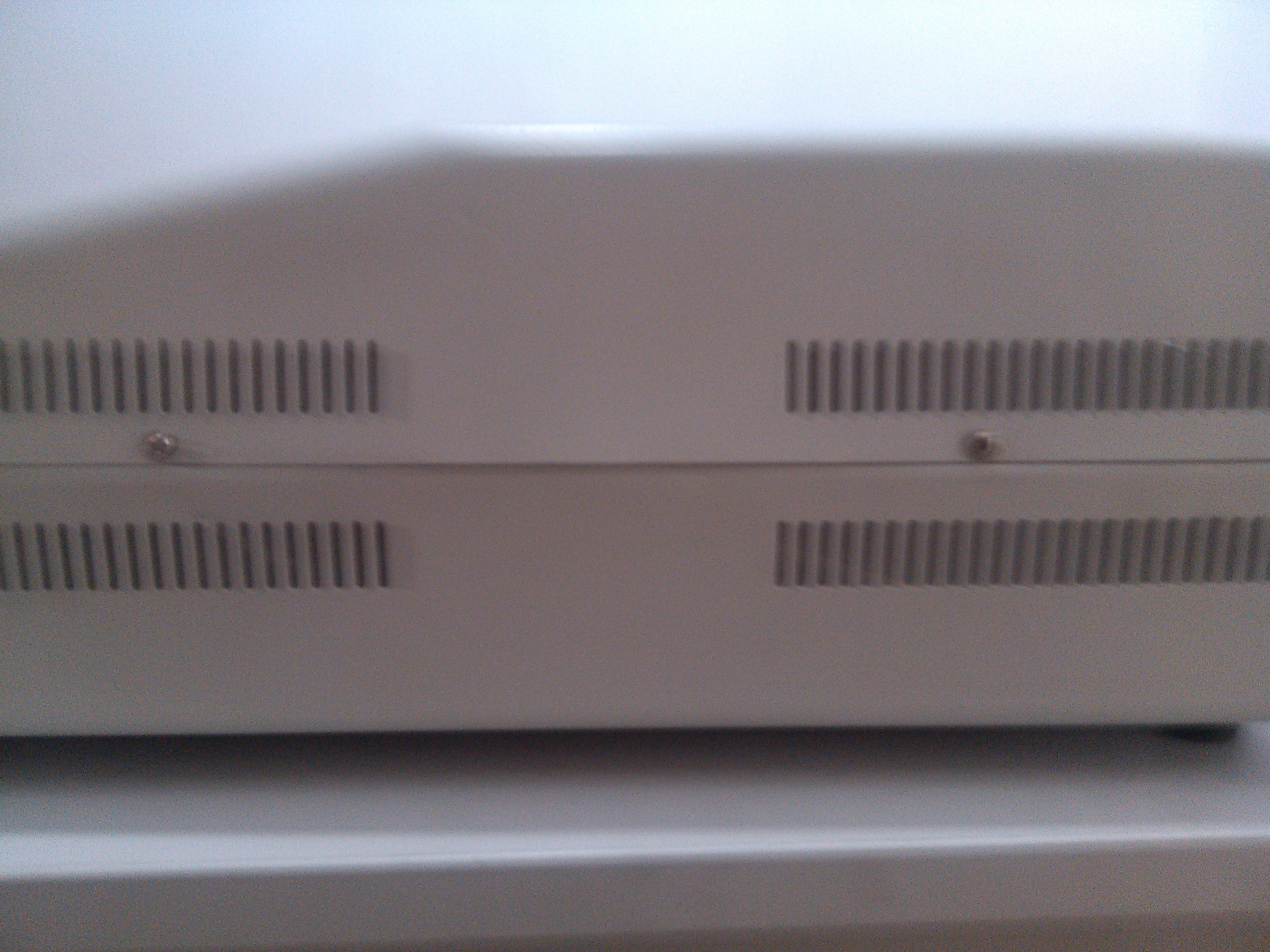

Most often, the reason for the inoperative stabilizer is a failed relay. in the process of operation, its contacts burn out, as a result of this there is no output voltage, so we should replace it.
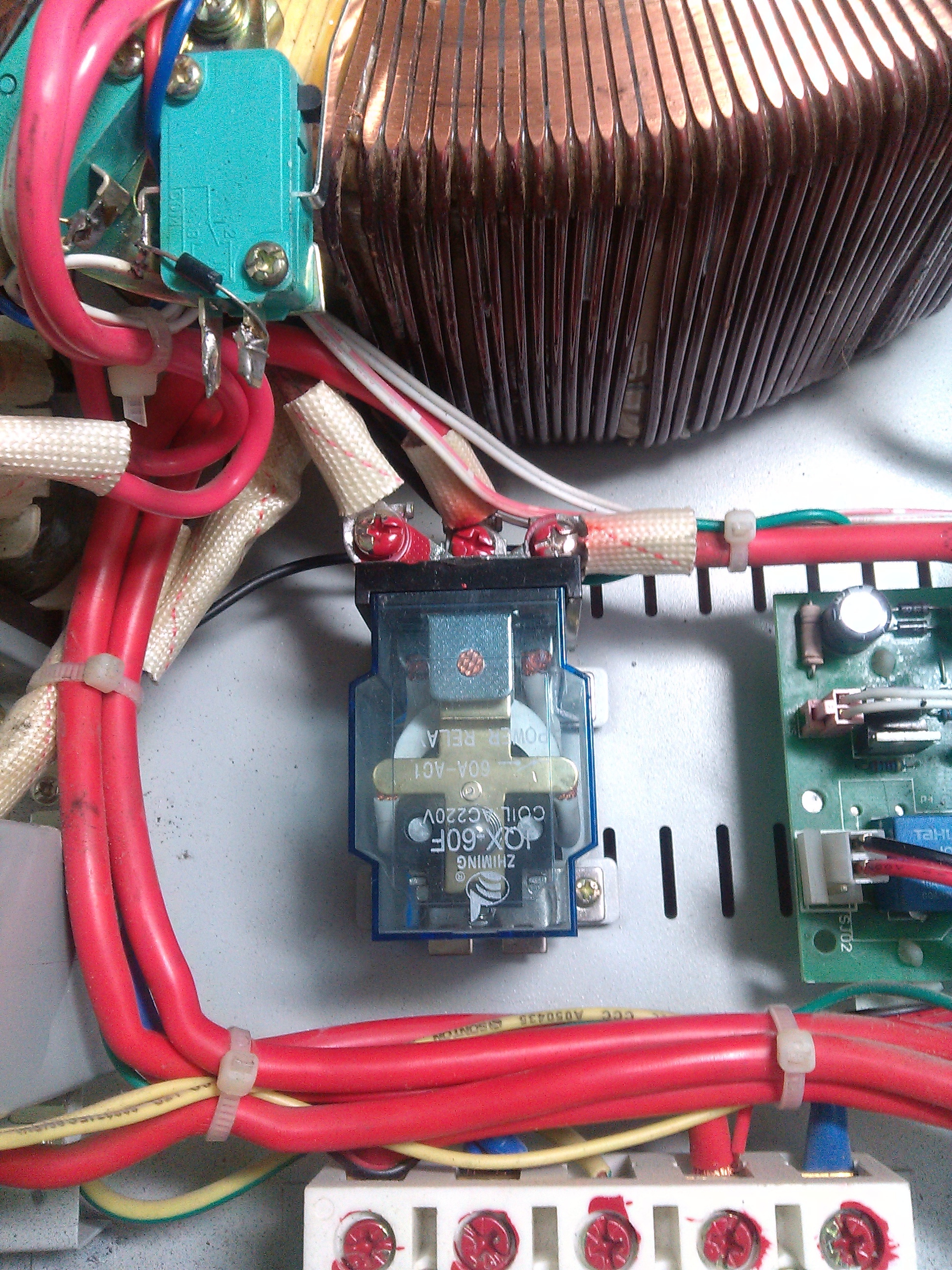
You should also check the rectifier diodes on the gearbox, since they also most often fail. In working order, they should not ring.
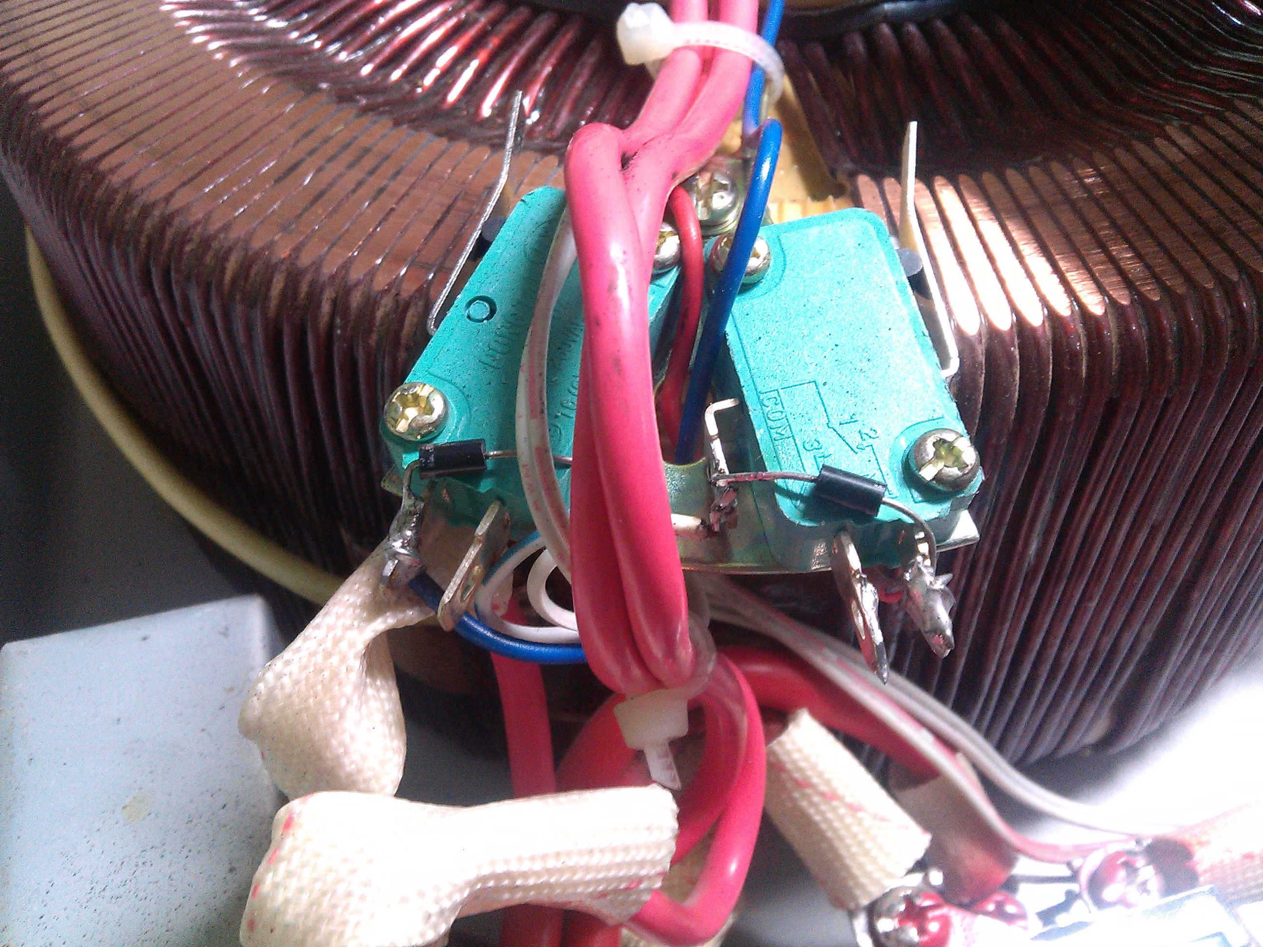
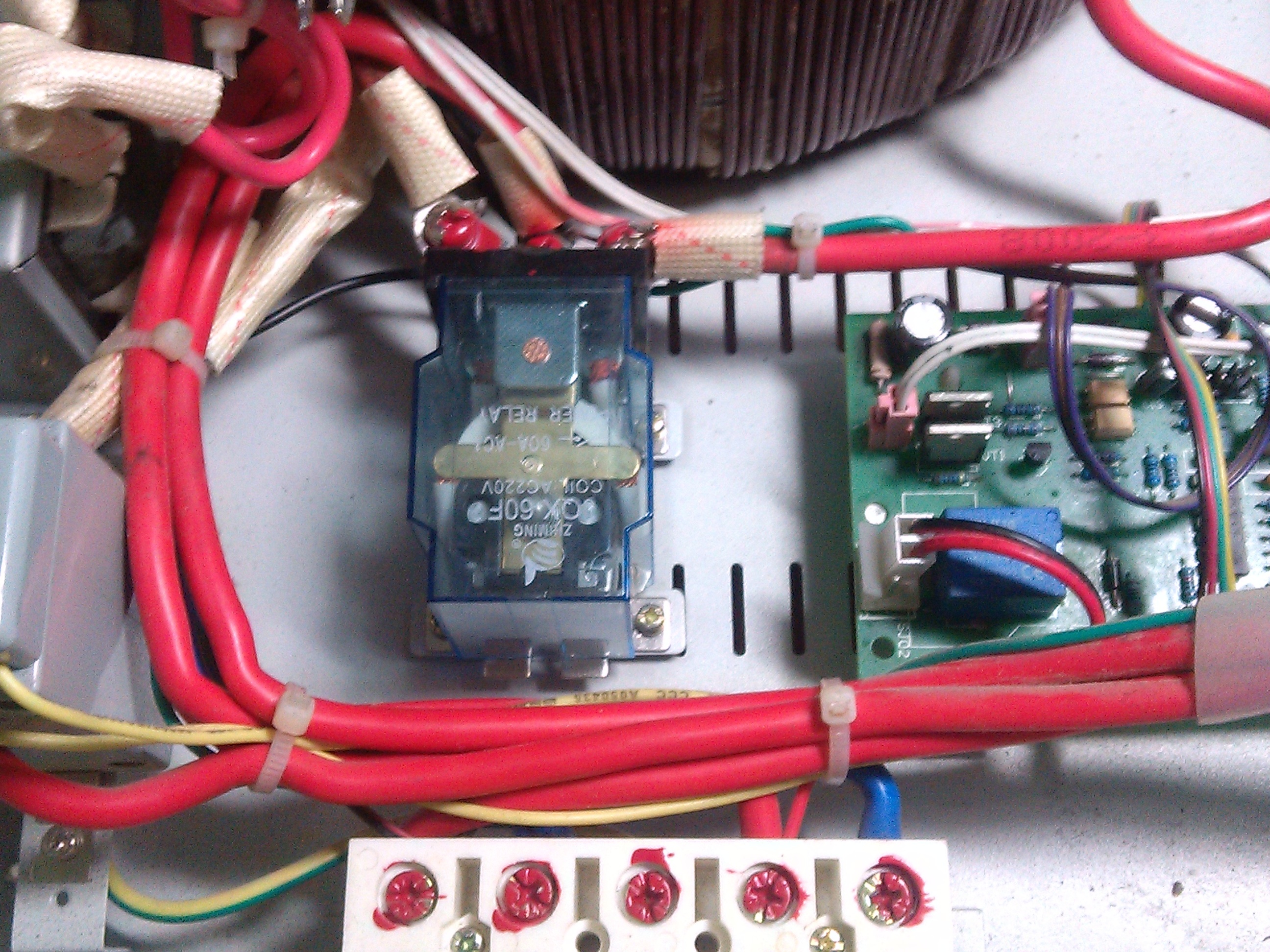

Next, we take sandpaper and wipe the spool on which the gearbox is located with it, because carbon remains on it during the operation of the gearbox, as a result of which there is no stabilization.
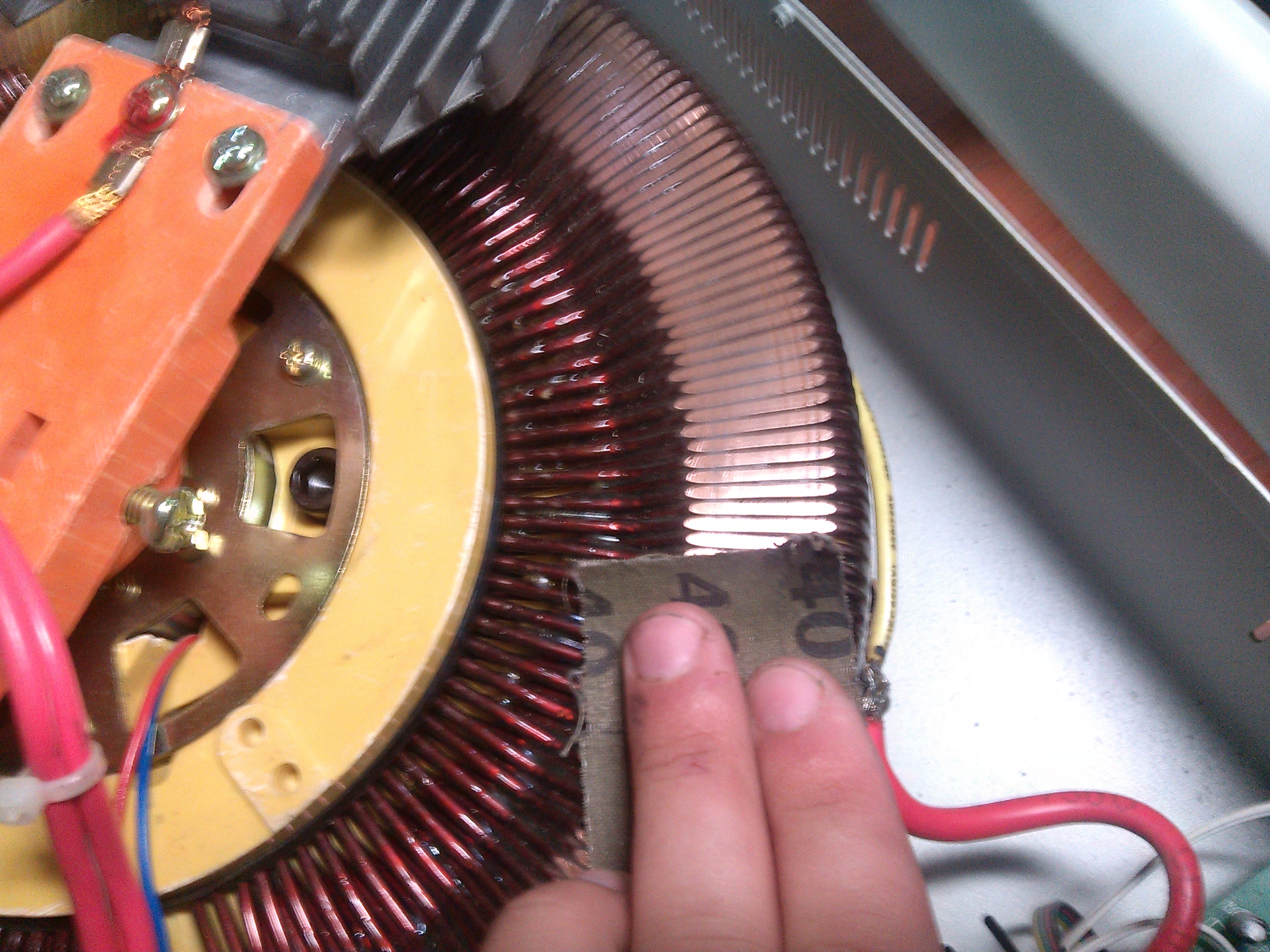
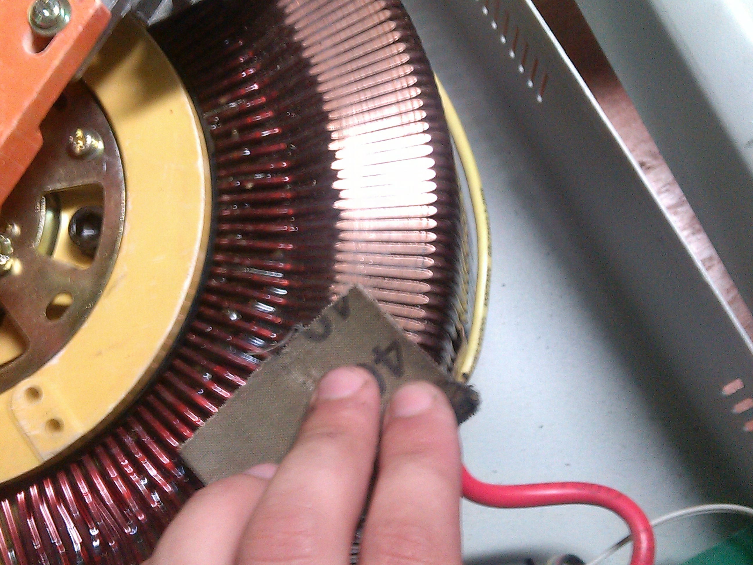

After the work done, we take the power cord and connect it to the input of the stabilizer and plug it into the network. Next, we take a multimeter and check the input voltage.
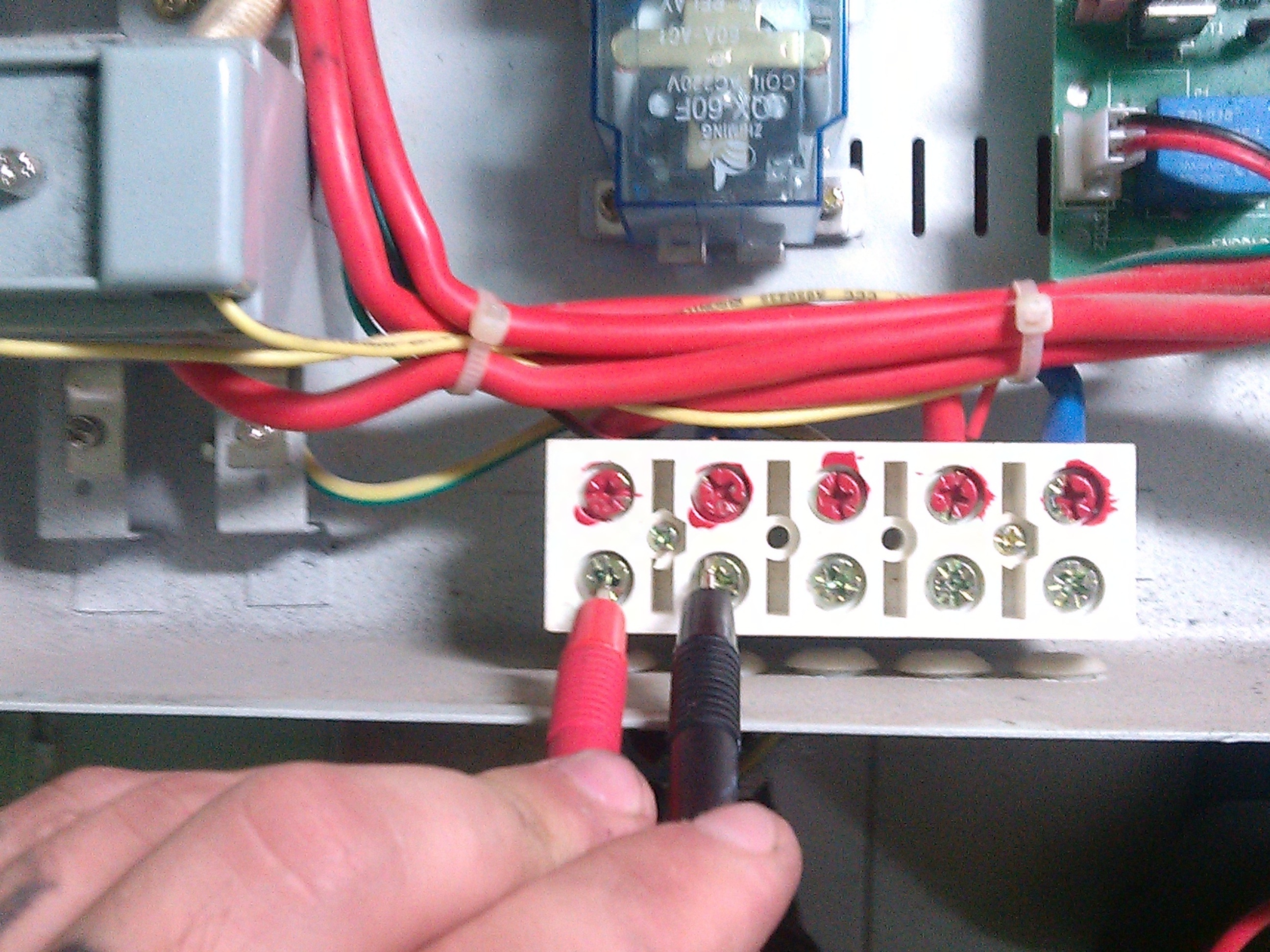
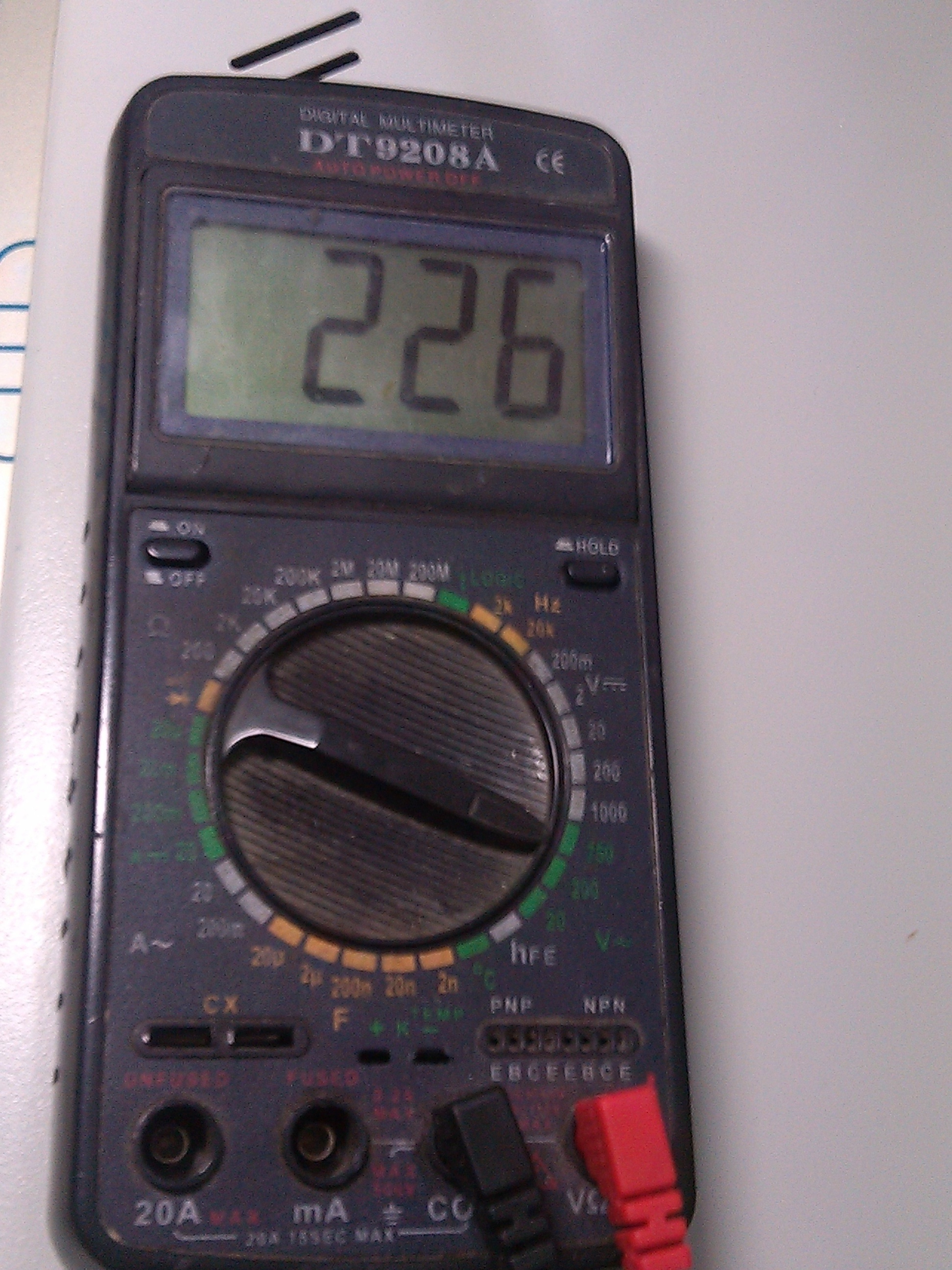

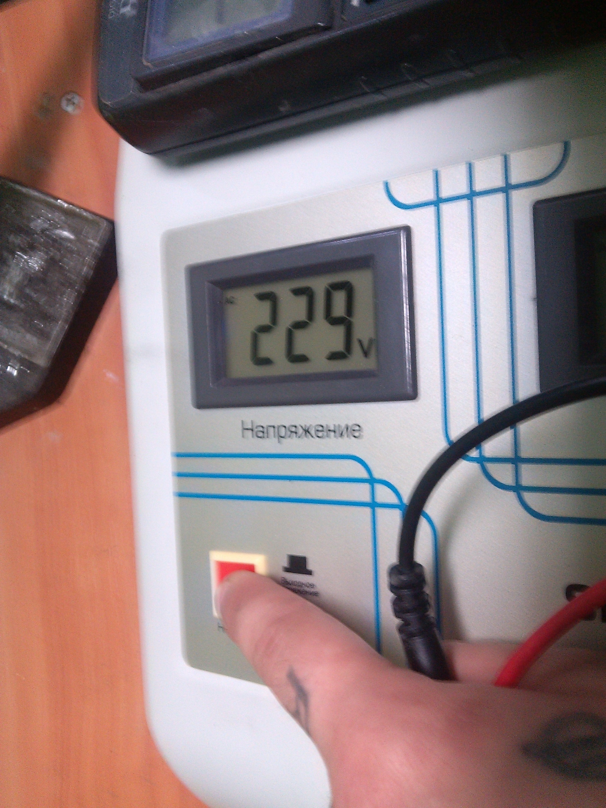

According to the readings of the multimert, we see that there is an input voltage, then we check the output voltage.
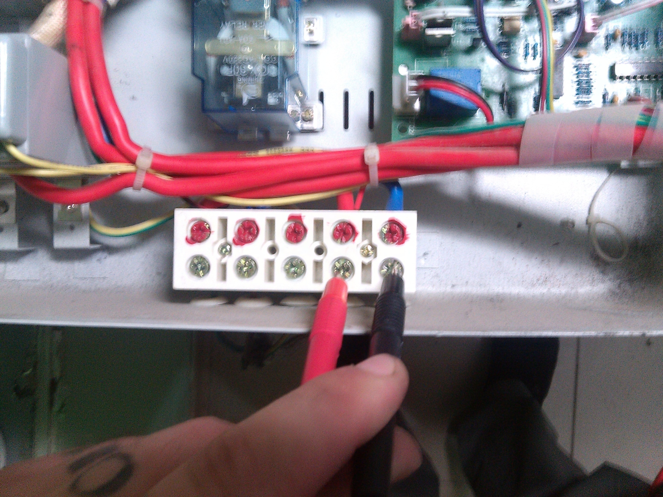
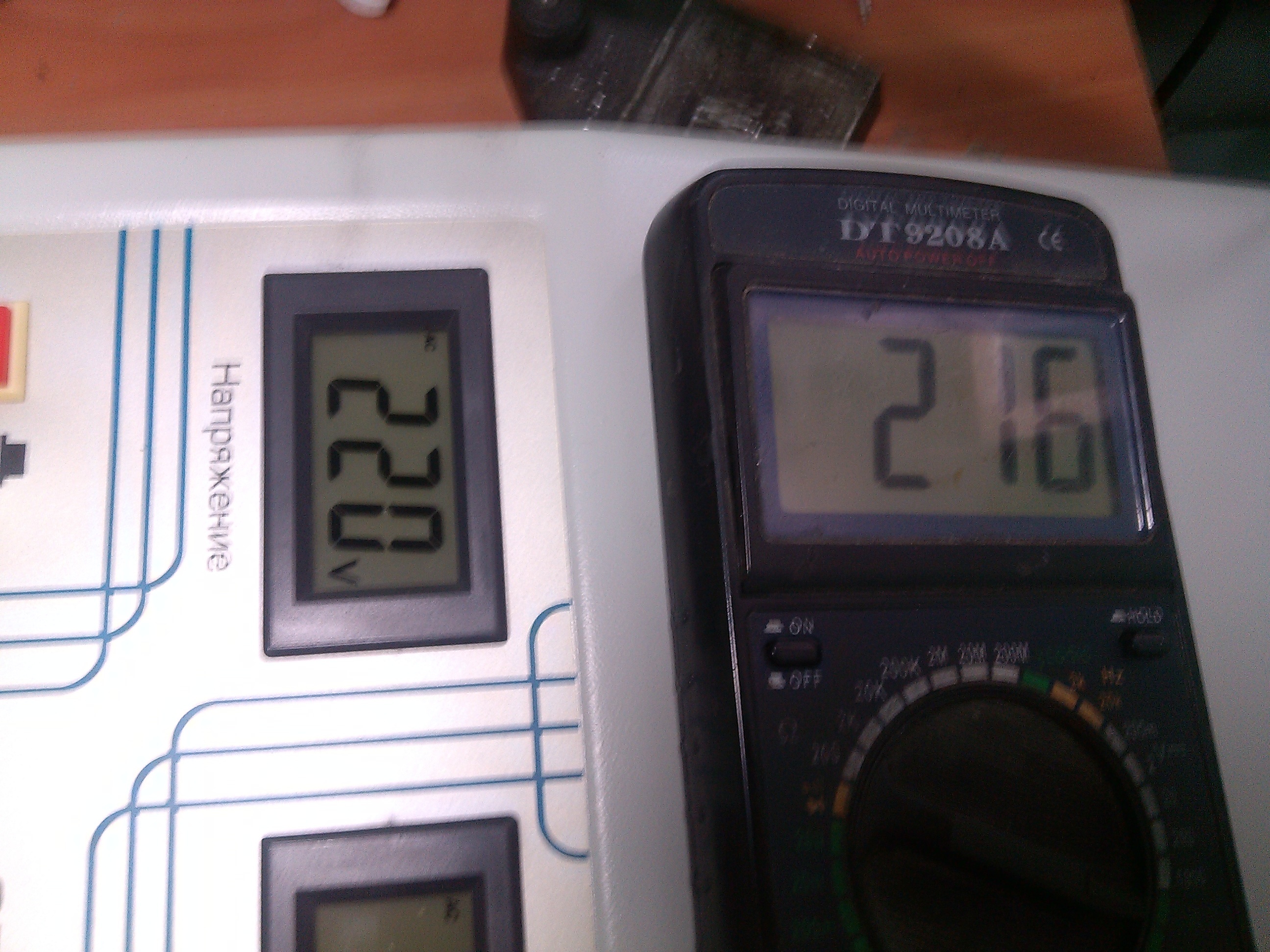

According to the readings of the multimeter, we see that the output voltage is also there, the error in the readings is minimal, which means that the stabilizer is working as it should. Putting everything together in the reverse order and continue to use a fully working stabilizer.
IMPORTANT. Remember that there is a high voltage in the stabilizer, we carry out repairs in compliance with safety precautions.
Graphic display of the main operating modes of voltage stabilizers
In one of the previous articles, the main types of voltage stabilizers were described, as well as instructions on how to connect them to the network with your own hands.This material introduces the main malfunctions of voltage stabilization devices and the possibility of their self-repair.
It must be remembered that a stabilizer of any type is a complex electrical or electromechanical device with many components inside, therefore, in order to repair it with your own hands, you must have a sufficiently deep knowledge of radio engineering. Repairing a voltage regulator also requires appropriate measuring equipment and tools.
Sophisticated stabilizer design
All voltage stabilization devices have a protection system that checks the input and output parameters for compliance with the rated value and operating conditions. Each stabilizer has its own protective complex, but several common ones can be distinguished. parameters, going beyond which will not allow the stabilizer to work:
- Rated input voltage (stabilization limits);
- Output voltage matching;
- Excess load current;
- Temperature range of components;
- Various signals from indoor units.
The list of control parameters of the stabilizers specified in the technical characteristics
It is necessary to check whether there is a short circuit in the load, the input voltage, the temperature conditions of operation and study the meaning of the error codes displayed on the displays.
The most difficult thing is to find a breakdown in the stabilizer on triac keys, which are controlled by complex electronics. For repairs, you must have a diagram of the device, measuring instruments, including an oscilloscope. According to the given oscillograms at the control points, a malfunction is found in the structural module of the stabilizer, after which it is necessary to check each radio component in the defective unit.
The main nodes of the triac stabilizer
In relay stabilizers, the most common cause of failure is the relay that switches the transformer windings. Due to frequent switching, the relay contacts can burn out, jam, or the coil itself can burn out. If the output voltage fails or an error message appears, check all relays.
Power switches of the relay stabilizer
For a master unfamiliar with electronics, it will be easiest to fix an electromechanical (servo) stabilizer - its operation and reaction to voltage changes can be seen with the naked eye immediately after removing the protective casing. Due to the relative simplicity of the design and high stabilization accuracy, these stabilizers are very common - the most popular brands are Luxeon, Rucelf, Resanta.
Resant stabilizer, power 5 kW
If the stabilizer transformer began to warm up without a noticeable load, then a short circuit may have occurred between the turns, called interturn. But, given the specifics of the operation of these devices, in which the terminals of the autotransformer or the secondary winding of the transformer are switched all the time in order to adjust the output voltage to the required value, we can conclude that the short circuit is somewhere in the switches.
Switching unit for relay stabilizer
In relay stabilizers (SVEN, Luxeon, Resanta) one of the relays can jam, and several turns of the transformer will be short-circuited... A similar situation can arise in thyristor (triac) stabilizers - one of the keys may fail and will "short" the output windings. The short-circuit voltage between turns, even with an adjustment step of 1-2V, will be enough to overheat the transformer.
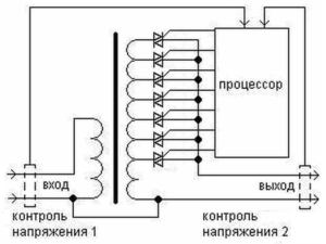
Switching unit of the stabilizer on triacs
It is necessary to check the triac keys to exclude this breakdown.The thyristor or triac is checked by a tester - between the control electrode and the cathode, the resistance during forward and reverse measurements should be the same, and between the anode and cathode, it should tend to infinity. This check does not always guarantee reliability, therefore, to guarantee it is necessary to assemble a small measuring circuit, as shown in the video:
In servo-driven stabilizers, the windings do not switch, but adjacent turns can also be closed due to a mixture of soot, dust and graphite sawdust clogged in the space between the turns. Therefore, servo-driven stabilizers such as Resanta and others require periodic preventive cleaning of contaminated contact pads.
Many users have noticed that the speed of wear and contamination of the contacts of servo stabilizers depends on the operating environment, in particular, dust and moisture. Therefore, the craftsmen came up with a way to modify Resant's stabilizers, installing a fan from a computer processor (cooler) opposite the most commonly used autotransformer sector.
Miniature fan for servo stabilizer modification
A constantly running fan prevents dust from settling on the contact pads, preventing contamination and wear by removing abrasive particles from the working area. In addition to cleaning the contact surfaces, the fan installed in the Resant stabilizer will also contribute to better cooling of the autotransformer.
Repair of stabilizers with a servo drive, such as Resanta, should begin with an inspection of the working contact area of the autotransformer.
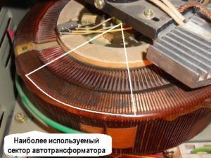
Carefully inspect the most worn areas of the contact turns
If the Resant's stabilizer was stored in a humid environment after a long time of operation, then the exposed unprotected copper contact pads could oxidize, which prevents the contact slider from contacting. Dust accumulated during downtime due to sparking can be flammable. Briefly about the prevention of electromechanical stabilizers and a demonstration of the servo drive in the video:
It is best to remove the pin slider from the servo shaft first. After that, you should use fine sandpaper to clean the contact pads to a metallic sheen. It is better to clean the auto-transformer contacts with a regular eraser. Then you need to carefully remove the accumulated sawdust and abrasive particles with a brush.
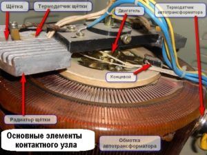
The device of the contact assembly of the servo stabilizer
The next step in repairing the servo stabilizer will be inspection, cleaning and possible replacement of the contact graphite brush. During operation, this brush heats up due to the currents flowing through it. But even more heating occurs due to poor contact between the brush and the contact plates of the autotransformer. Due to the increased heating and arcing during the movement of the slider, the brush burns out even more, thereby contaminating the contact pads and the gaps between them.
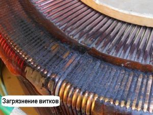
Severe contamination of the contacting turns of the autotransformer
Thus, the acceleration of pollution is gaining an avalanche-like character, which leads to rapid wear of the autotransformer contacts and burnout of the contact brush, after which the stabilizer will stop supplying voltage. Depending on the protection system in the servo-driven stabilization devices from the Resanta company, or from other manufacturers, in the event of a break in the output voltage, the protective automatics must be triggered.
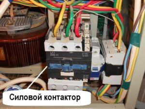
Contactor - power element of protective automation
That is why it is so important prevention servo stabilizers. Often, Resant's repair ends with cleaning the contacts and replacing the contact brush. But, sometimes in servo stabilizers the servo itself fails. Servo failure can be caused by wear on the gearbox, burned out motor, or lack of voltage.Having taken out the motor together with the gearbox, it is necessary to check the mechanism by turning the shaft.
The electronic control board of any type of stabilizer contains many components, including microcircuits, which cannot be tested without special equipment. But it's worth it carefully inspect the board itself and check the components on it for traces of high temperature.
Sophisticated electronic circuit board of the relay stabilizer
Overheated resistors are the first to "catch the eye" and sometimes carbonize to such a state that it is impossible to recognize their markings - you will have to study the stabilizer circuit. Overheating of the resistors indicates a breakdown in other elements of the circuit - most often in power transistor switches. A close examination of the transistors can reveal blackening from overheating, and even mechanical cracks.
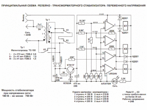
An example of a relatively simple relay stabilizer circuit
The cause of a malfunction of any circuit can be a breakdown in the capacitor. Very often electrolytic capacitors swell, which is why they differ significantly in shape from other capacitors. But the breakdown of a capacitor can not always be determined by its swelling - the electrolyte inside can dry out, from which it will lose its electrical conductivity.
An illustrative example of a blowing capacitor
On the board itself, traces of the impact of freelance overcurrents can also be seen - some tracks may burn, and the contacts may be soldered off, or close together due to the spreading molten solder heated by large currents. In addition, traces of strong heating of parts may remain on the board - from a change in shade to charring of the PCB.
An example of a burned-out track on the board
Visual inspection of the defective module can tell the technician in which direction to diagnose. But, as a rule, the repair of electronic boards of stabilizers is not limited to replacing clearly damaged parts and requires additional checking of various components using special equipment. Therefore, if the continuity of the power transistors and other elements did not reveal the cause of the breakdown, it is better to take the electronic board to the workshop.
The mains voltage stabilizer is designed to protect the devices connected to it from failure, but sometimes it itself can break down. The materials in this article can help you restore the functionality of such a device yourself.
The other day, one of my friends, cleaning up his father's garage, found something that was not working, but in a decent building. Deciding that it was a charger, he came to me in the hope that the device could be restored. As a result, the charger turned out to be. 1 kW mains voltage stabilizer.
Already by the fact that the power cord was cut off, one can judge a malfunction of the device.
I unscrew the fuse holder - there is no fuse at all.
Remove the stabilizer cover. Before us is a classic autotransformer, equipped with a servo drive controlled by automation assembled on a separate board. Although the inside of the stabilizer is covered with dust, the main thing is that there are no oxidized or burnt out parts.
On the reverse side of the autotransformer there is a movable slider with a graphite brush-current collector fixed at the end and two limit switches.
As you can see in the photo, the contact track has a noticeable coating of graphite, and the copper wire has oxidized and turned green in places. At the end of the repair, all this will need to be cleaned with fine sandpaper.
We proceed to replace the power cord. To do this, unscrew the screws securing the autotransformer and take it out, bite off the wires on the switch and on the ground terminal with pliers.
Using pliers, remove the remnants of the cord.
As a new cord, you can use the cord from the computer system unit - when connecting the latter to the uninterruptible power supply unit, the cord from the uninterruptible power supply kit is used, and the “native” one is usually sent “out of sight”.
Having bitten off the unnecessary part with pliers, we insert the end of the cord into the hole with the standard seal. Since there is practically no gap, we pull the cord to the required length using long-nose pliers - unlike pliers, the working part of this tool is somewhat longer, which will allow it to be used with somewhat greater convenience as a lever, taking the stabilizer body as the fulcrum.
We cut the wires and solder them into place. Blue and brown - to the switch terminals instead of the bitten off ones.
Solder the grounding terminal to the yellow wire with a green stripe and install the autotransformer in place.
Now we check the quality of the contact of the brush with the surface of the wires. To do this, it is enough to make sure that there is a gap between the bodies of the runner and the brush holder. The normal size of the gap is 1-1.5 mm, a smaller one will not provide good contact and overheating and sparking may appear, a larger one will cause premature brush wear.
The photo shows the moment of setting the required gap size.
The force of pressing the brush to the wires of the autotransformer is regulated by moving the current collector slider along the shaft. Before the adjustment operation, we loosen its fixation - in the photo the screw fixing the position of the slider is enclosed in a red circle.
If during the adjustment process the slider turns around its axis, and you have not fixed its initial position, do not worry, in this case it is not critical, because The servo gearbox has no restrictions on the number of revolutions in either direction, and the extreme positions of the slider are limited by limit switches.
Note that this screw can unscrew itself, and then the slider will begin to turn - and this, in turn, will lead to the failure of the equipment connected to the stabilizer. Therefore, we periodically check the reliability of fixing this unit, not forgetting that excessive force when tightening the same screw can lead to the destruction of the ceramic body of the slider.
Now we take fine-grained sandpaper and clean the current-collecting “track” of the autotransformer, after which we wipe it with a cotton swab moistened with alcohol, thus removing dust and metal particles.
Having installed the fuse, we proceed to testing. The difference in the readings of the voltmeter of the stabilizer and the control voltmeter of 1-4 volts is insignificant and you can not pay special attention to this fact.
What you should pay attention to is the rating of the installed fuse. It is not recommended to install larger fuses here. So, on the body of the device there is an inscription indicating the fuse rating of 7 amperes. Since this was not found, it was applied at 6.3 amperes.
| Video (click to play). |
So, the stabilizer is assembled, and the connected charger from the screwdriver confirms its performance.


