In detail: do-it-yourself stabilizer repair from a real master for the site my.housecope.com.
Like any other electronic equipment, voltage stabilizers are susceptible to damage. Some models have a long service life, others break more often. Much depends not only on the quality of the installation, but also on the thoughtfulness of the circuitry.
The most susceptible to breakdowns are units that contain mechanical devices: a brush assembly in electromechanical stabilizers and electromagnetic relays in relay ones. Failures of thyristor devices are much less common and are mostly associated with abnormal voltage values and low-quality components.
It is impossible to foresee all variants of breakdowns within the scope of one article, and only highly qualified specialists are capable of repairing complex electronic equipment. However, some damage can be repaired at home.
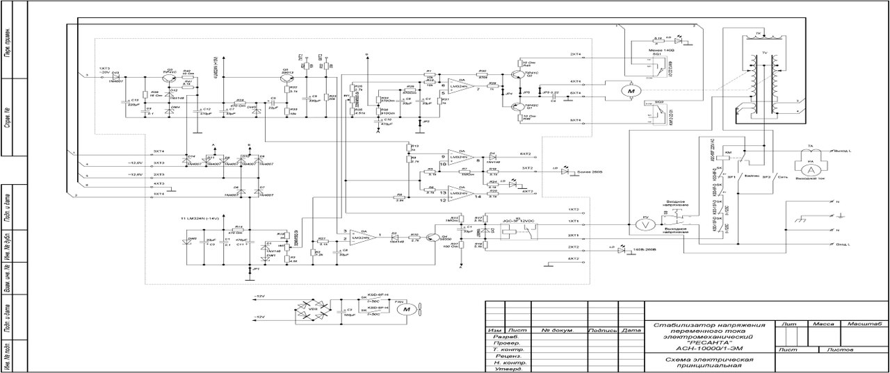
Further, we will talk about the repair of the Resant stabilizer, as the most common brand. Other types of devices are either clones or have similar circuitry and internal structure.
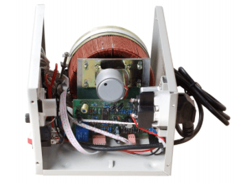
Any repair to stabilizers should begin with a visual inspection of the interior of the device. First of all, you should pay attention to the absence of visible damage: burning of the tracks on the board, the terminals of the elements, the integrity of the transformer windings. Often breakdowns in the stabilizer occur due to improper operation of the control circuit, which is caused by the loss of capacity of electrolytic capacitors. Such elements usually have a bulged end of the body and must be replaced first. Let them not be the cause of the breakdown at the moment, but next time they will make themselves felt. The capacity of the replaceable capacitors should be the same as on the original, and the operating voltage may exceed the required - there is nothing wrong with that, even better.
Video (click to play).
Important! When replacing capacitors, do not reverse polarity.
Further search options depend on the type of stabilizer used.
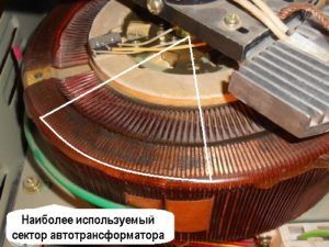
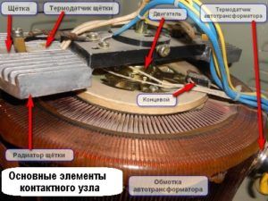
A significant part of the damage to electromechanical devices is associated with critical wear of the servo brushes. The movement of the brushes along the bare part of the windings occurs with significant friction, as a result of the passage of large currents through the brush-winding contact, the elements of the brush assembly are heated. All this leads to the destruction of the brush material. If during inspection it is revealed that the brush is damaged, its wear prevents it from tightly pressing against the winding, then the brushes must be replaced.
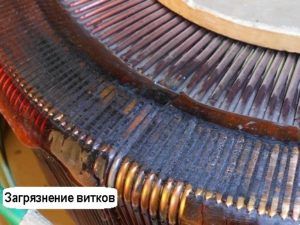
Another case of breakdown is the burning of the winding wire and the closure of adjacent turns with electrically conductive dust from the brushes. To restore performance, you need to clean the bare part of the winding from oxides with fine-grained emery paper.
Important! Do not use coarse grain pelt, as the grooves on the surface of the wires will cause strong sparking and burning of the windings and brushes. The main criterion for choosing a grain size is the absence of visible grooves on the surface of the wire.
Dust between the windings can be removed with a strong blast of air from the compressor. Not everyone has such a device, so you can use an old hard-bristled toothbrush. The work will be easier if the brush is moistened with alcohol of the maximum concentration.
Note! Diluted alcohol, solvents, and especially water should not be used.
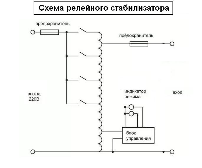
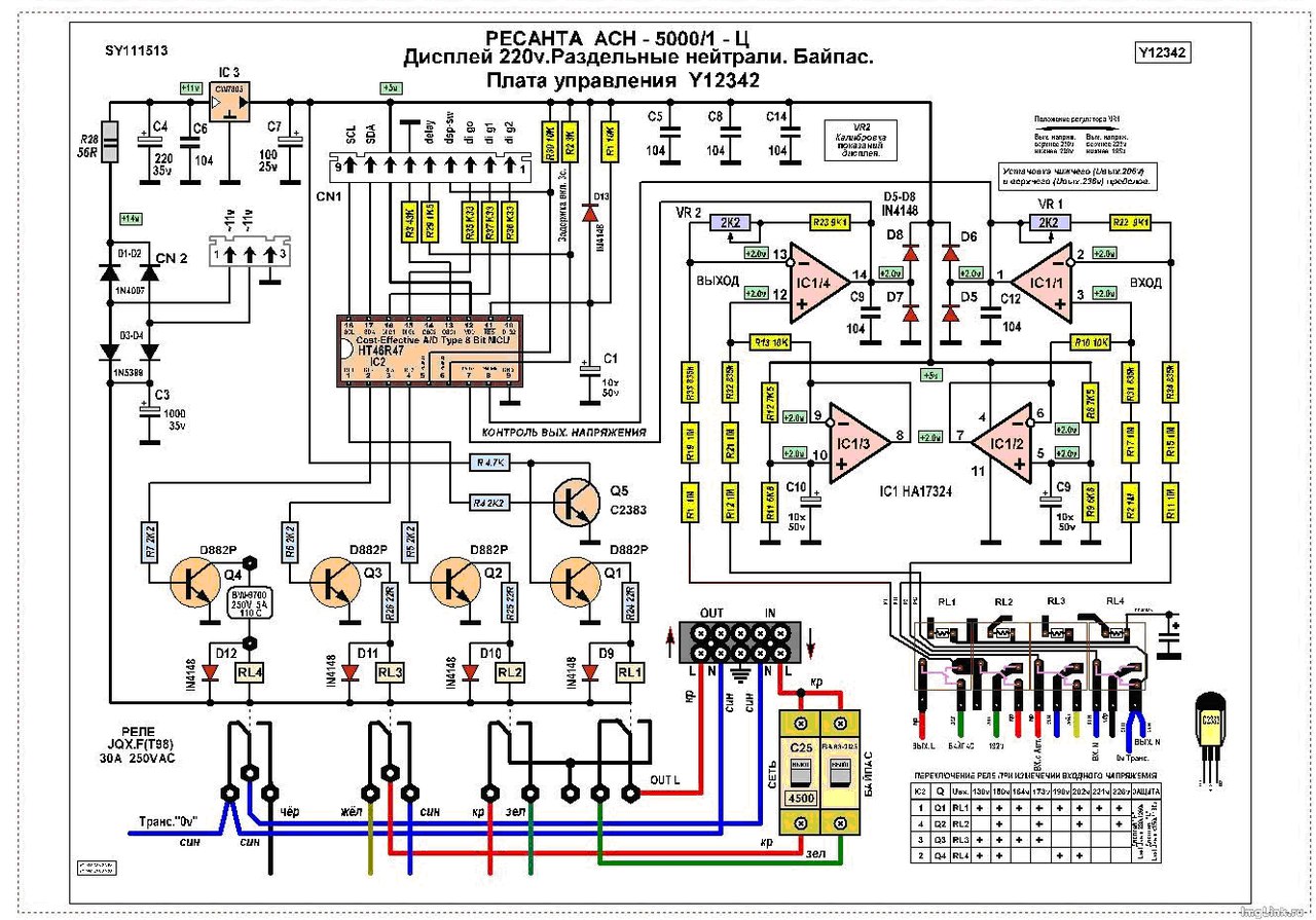
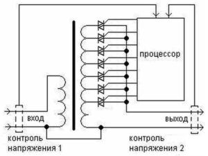
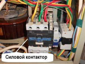
In relay stabilizers, electromagnetic relays have the least reliability. The flow of large currents through the contacts causes their burning or even sintering.The latter is dangerous in that it can cause a short circuit of part of the autotransformer windings.
Resant voltage stabilizers or similar ones have five relays on the board, which switch parts of the autotransformer windings according to a certain algorithm. The predominant fluctuations in the input voltage of about one value lead to the fact that only part of the relay, one or two, are constantly in operation. Therefore, it is they who, first of all, fail.
The search for a faulty element is made difficult by the fact that small-sized relays are low - and medium-power stabilizers have an opaque non-separable case. Sometimes it is possible to identify a faulty relay by lightly tapping the body of each relay with an insulated screwdriver handle. Under mechanical stress, the resistance between the burnt contacts can be restored, and the sintered contacts can open. Found relays must be changed without fail.
Powerful devices can have a relay in a transparent case, through which the operation of the contact groups is visually observed. In addition, the body is collapsible for cleaning. Burnt contacts can be tidied up with fine-grained emery cloth. The grain size should be even smaller than when cleaning the windings of electromechanical stabilizers.
Relay in transparent housing
In the event that a visual inspection did not reveal any damage, the relay can be removed from the board and the contacts can be ringed using an ohmmeter. The location and numbering of contacts are shown on one side of the relay housing. The device should show infinitely high resistance between normally open contacts, and close to zero between closed contacts. Having applied a constant voltage of 12 V to the control winding, they ring the contacts again. Now those that were open should close and vice versa.
Important! The relays have powerful leads and require the use of a suitable soldering iron for soldering. Do not overheat the printed conductors.
If there is a LATR - laboratory autotransformer, then troubleshooting and repair of the Resant or other device can be greatly simplified. To do this, assemble the simplest chain:
The LATR input is connected to the power supply;
LATR output - to the input of the stabilizer;
An AC voltmeter is connected to the output of the stabilizer.
Rotating the LATRA adjustment knob from minimum to maximum values, observe the operation of the stabilizer and the voltmeter readings. In a mechanical stabilizer, when the input voltage changes, the servo shaft with the brush assembly should rotate, and the output voltage should correspond to the rated voltage.
In relay stabilizers, you can hear the switching on of various relays, and the output voltage will change stepwise with a swing of no more than 10V when the input voltage changes from the minimum to the maximum.
This repair of the voltage stabilizer is more complicated and requires knowledge of the operation of electronic circuits. In relay and thyristor stabilizers, key transistors that control the operation of triacs or relays are subject to verification. The transistors are checked according to the usual method after they have been soldered from the board. The resistance between collector and emitter must be infinite for any polarity of measurement.
Resistance base - collector and base - emitter in one polarity should also be infinitely large, and in the other - be insignificant.
In electromechanical stabilizers, you can observe the lack of rotation of the servo shaft when the input voltage changes. The reason for this is a malfunction of the HA17324a operational amplifier. This IC has a low cost and is widely available on the market.
Repair of the voltage stabilizer in some cases is possible with your own hands with a minimum of time. It should be borne in mind that the safety of family members may depend on the correctness of the repair.If you are not completely confident in your abilities, then it is better to entrust this matter to a professional.
VIDEO
Resanta voltage stabilizers can be found in many apartments in our country, which is understandable. This is due to the fact that such units make it possible to normalize the operation of all electrical appliances that are present at home. In other words, they allow you to save quite expensive equipment in the event of an overload in the network, or in case of voltage surges, thereby significantly extending the operational life of all electrical equipment.
However, the operation of the voltage stabilizer also carries the risk of certain breakdowns, the only way out of which is timely repair .
There may be several reasons for this - from improper operation to natural causes of breakdown, i.e. long service life.
To avoid this, you must exactly follow the instructions that come with the kit, which allows you to significantly extend the service life of the unit in the correct mode of operation. If, nevertheless, a breakdown did happen, then you need to know what methods you need to properly carry out repairs with your own hands, so as not to further aggravate the situation. In this article, we will look at the main malfunctions, as well as ways to eliminate them in a timely manner.
This video shows the Resant's stabilizer with a malfunction
VIDEO
The constructive structure of the Resant voltage stabilizer is as follows:
automatic transformer;
the electronic unit;
voltmeter;
a control that is responsible for starting and disconnecting some windings.
This manufacturer produces many different types of stabilizers , therefore, these organs for connecting the windings will differ. We will talk about all these nuances a little later, during the consideration of the repair procedure.
In this design, the decisive factor is the electronic unit, which carries out the general control of the entire system of the unit. He is responsible for the operation of the voltmeter, and also receives information about the power of the input voltage. Then, the block compares the obtained values with the optimal ones, determining the next action, i.e. whether you need to add a few volts or, on the contrary, subtract a certain amount.
Further, along the chain, there is a determination of the necessary windings - which of them need to be started and which ones to be disabled. Then, the electronic unit performs one of these actions, after which all electrical appliances in the apartment receive a stable current.
Of course, the stabilization process itself can be slightly different, depending on the type of device produced.
This difference applies to the types of windings, as well as the methods of starting and disconnecting them. Today, the Resanta company produces two types of these stabilizers:
Electromechanical type.
Relay.
Accordingly, their repair will be somewhat different.
Let's start our consideration with stabilizers of the electromechanical type. In its design there is a servo drive, which starts and turns off the windings in the device.
The servo itself consists of a motor on which an electrical contact (brush) is located. When the armature of this motor moves, accordingly, this brush also rotates, constantly contacting with copper windings. The width of this brush allows for a complete wrap-around of the entire winding, which allows the phase not to be lost.
In order for the brush to move in a given direction with the desired characteristics, an error voltage arises in the device. Then, this voltage value rises. Then it is transmitted to the engine, which makes the armature rotate in the optimal direction. Accordingly, the brush also moves, like the armature, in the same predetermined direction. In this case, direct contact with the windings is carried out.
The error voltage value will be proportional to the value formed by the difference between the real voltage value at the input and the value that should be there. This signal can have one of two polarities, each of which specifies a certain direction of movement. Below is a diagram of a similar voltage regulator:
Regardless of the specific model, the structure of this voltage regulator will be almost the same. They differ among themselves by different power values and individual circuit elements.
All relay stabilizers equalize the current values by surges. This is because the relay starts or turns off the turns located on the second winding. An electromechanical stabilizer performs this process more smoothly than a relay one.
Relay units from Resant connect the turns until they find the right one. All these turns are conventionally divided into subgroups, and from each turn there is an output to which the current flows when the device is started.
The diagram of all relay stabilizers of this brand shows that there are about four relay elements in its design. In some cases, this number can be equal to five (SPN models).
In the case of relay stabilizers, it is the relay that is the most vulnerable point of the entire device. This is due to the fact that it is in a constant operating mode, which significantly increases the risk of failure .
Having considered the principles of operation of both types of voltage stabilizers, we can conclude that it is their main components that are the most frequently breaking system components. We are talking about a servo drive in electromechanical devices, as well as relays in relay ones.
In the first case, the constant movement of the servo leads to periodic friction of the turns of the coil and brush, which leads to excessive overheating of these components. It also causes severe wear and tear and sparks from copper wires.
It is also necessary to bear in mind the fact that the current value periodically changes in the network, which provokes a similar change in the movement of the servo. Such unstable operation can lead to the failure of this device.
Repair of one of the faults is demonstrated in the video.
VIDEO
The repair of the Resant's stabilizer can be roughly divided by the type of breakdown.
First, consider the situation when the Resant servo motor has failed. There are two ways out of this problem. :
Buy a new motor, then install it in the device.
Try to repair the damaged one.
While everything is clear with the first case, the second requires detailed consideration. It is important to understand that in case of successful repair work, the restored engine will not be able to work for a long time, i.e. this is a temporary measure.
Everything our actions will boil down to the following:
Disconnect the servo motor from the general structure. Then we connect it to a power source with sufficient power.
It is necessary to supply a current of 5 V to the outputs of the motor. The indicator of the current strength must be at least 90 mA.
The implementation of these manipulations will normalize the operation of the stabilizer. Next, you need to connect the motor back to the circuit.
The circuit is quite simple: the input cable is connected to the input terminal, the neutral cable is connected to the neutral terminal. The same manipulations are performed for the output cables. Also, remember to connect the ground wire.
Failure of the relay is often leads to breakage of transistors ... For example, in the ASN-5000 model, there are D882P transistors. The diagram is shown below:
If these transistors fail, then you need to purchase new ones in their place.You can buy them quite freely, because many specialized stores sell equipment and components of the Resanta brand.
You can also try to repair damaged parts:
First you need to remove the relay cover. Next, remove the movable contact, freeing it from the spring.
Using sandpaper, we clean off all carbon deposits from the contact. We carry out this manipulation for both contacts - upper and lower.
Then we lubricate the contacts with gasoline, after which we assemble the relay structure.
Another possible problem is the disordered switching on of the display, as well as the switching on of the relay itself. The reason for this may be the XTA1 resonator, which may have an incorrect soldering.
The repair is as follows :
We solder this resonator with a soldering iron.
We clean the leads with sandpaper.
We solder the resonator back.
Specialist's story about Resant's repair
VIDEO
To make diagnostics, we need a LATR device, i.e. laboratory autotransformer of controlled type. We connect the stabilizer to this device, with which you need to change the voltage values. In parallel, we are monitoring the work of the Resant stabilizer.
The implementation of repair work, in this case, can be done at home. At the same time, it is assumed that the person performing these manipulations will be well acquainted with such a technique, have the skills of proper soldering and some knowledge in electronics. If a person does not possess this, then it would be more expedient to contact specialists.
There are quite a few similar service centers in Moscow and St. Petersburg. In particular, "Demal-Service", located at the address: Moscow, st. 1st Vladimirskaya, house 41.
In St. Petersburg there is a service center of the company itself, located at the address: st. Chernyakovsky, house 15.
Graphic display of the main operating modes of voltage stabilizers
In one of the previous articles, the main types of voltage stabilizers were described, as well as instructions on how to connect them to the network with your own hands. This material introduces the main malfunctions of voltage stabilization devices and the possibility of their self-repair.
It must be remembered that a stabilizer of any type is a complex electrical or electromechanical device with many components inside, therefore, in order to repair it with your own hands, you must have a sufficiently deep knowledge of radio engineering. Repairing a voltage regulator also requires appropriate measuring equipment and tools.
Sophisticated stabilizer design
All voltage stabilization devices have a protection system that checks the input and output parameters for compliance with the rated value and operating conditions. Each stabilizer has its own protective complex, but several common ones can be distinguished. parameters , going beyond which will not allow the stabilizer to work:
Rated input voltage (stabilization limits);
Output voltage matching;
Excess load current;
Temperature range of components;
Various signals from indoor units.
The list of control parameters of the stabilizers specified in the technical characteristics
It is necessary to check whether there is a short circuit in the load, the input voltage, the temperature conditions of operation and study the meaning of the error codes displayed on the displays.
The most difficult thing is to find a breakdown in the stabilizer on triac keys, which are controlled by complex electronics. For repairs, you must have a diagram of the device, measuring instruments, including an oscilloscope. According to the given oscillograms at the control points, a malfunction is found in the structural module of the stabilizer, after which it is necessary to check each radio component in the defective unit.
The main nodes of the triac stabilizer
In relay stabilizers, the most common cause of failure is the relay that switches the transformer windings. Due to frequent switching, the relay contacts can burn out, jam, or the coil itself can burn out. If the output voltage fails or an error message appears, check all relays.
Power switches of the relay stabilizer
For a master unfamiliar with electronics, it will be easiest to fix an electromechanical (servo ) stabilizer - its operation and reaction to voltage changes can be seen with the naked eye immediately after removing the protective casing. Due to the relative simplicity of the design and high stabilization accuracy, these stabilizers are very common - the most popular brands are Luxeon, Rucelf, Resanta.
Resant stabilizer, power 5 kW
If the stabilizer transformer began to warm up without a noticeable load, then a short circuit, called interturn, may have occurred between the turns. But, given the specifics of the operation of these devices, in which the terminals of the autotransformer or the secondary winding of the transformer are switched all the time in order to adjust the output voltage to the required value, we can conclude that the short circuit is somewhere in the switches.
Switching unit for relay stabilizer
In relay stabilizers (SVEN, Luxeon, Resanta) one of the relays can jam, and several turns of the transformer will be short-circuited ... A similar situation can arise in thyristor (triac) stabilizers - one of the keys may fail and will "short" the output windings. The short-circuit voltage between turns, even with an adjustment step of 1-2V, will be enough to overheat the transformer.
Switching unit of the stabilizer on triacs
It is necessary to check the triac keys to exclude this breakdown. The thyristor or triac is checked by a tester - between the control electrode and the cathode, the resistance during forward and reverse measurements should be the same, and between the anode and cathode, it should tend to infinity. This check does not always guarantee reliability, therefore, to guarantee it is necessary to assemble a small measuring circuit, as shown in the video:
VIDEO In servo-driven stabilizers, the windings do not switch, but adjacent turns can also be closed due to a mixture of soot, dust and graphite sawdust clogged in the space between the turns. Therefore, servo-driven stabilizers such as Resanta and others require periodic preventive cleaning of contaminated contact pads.
Many users have noticed that the rate of wear and contamination of the contacts of servo stabilizers depends on the operating environment, in particular, on dust and moisture. Therefore, the craftsmen came up with a way to modify Resant's stabilizers by installing a fan from a computer processor (cooler) opposite the most frequently used autotransformer sector.
Miniature fan for servo stabilizer modification
A constantly running fan prevents dust from settling on the contact pads, preventing contamination and wear by removing abrasive particles from the working area. In addition to cleaning the contact surfaces, the fan installed in the Resant stabilizer will also contribute to better cooling of the autotransformer.
Repair of stabilizers with a servo drive, such as Resanta, should begin with an inspection of the working contact area of the autotransformer.
Carefully inspect the most worn areas of the contact turns
If the Resant's stabilizer was stored in a humid environment after a long time of operation, then the exposed unprotected copper contact pads could oxidize, which prevents the contact slider from contacting. Dust accumulated during downtime due to sparking can be flammable.Briefly about the prevention of electromechanical stabilizers and a demonstration of the servo drive in the video:
VIDEO
It is best to remove the pin slider from the servo shaft first. After that, you should use fine sandpaper to clean the contact pads to a metallic sheen. It is better to clean the auto-transformer contacts with a regular eraser. Then you need to carefully remove the accumulated sawdust and abrasive particles with a brush.
The device of the contact assembly of the servo stabilizer
The next step in repairing the servo stabilizer will be inspection, cleaning and possible replacement of the contact graphite brush. During operation, this brush heats up due to the currents flowing through it. But even more heating occurs due to poor contact between the brush and the contact plates of the autotransformer. Due to the increased heating and arcing during the movement of the slider, the brush burns out even more, thereby contaminating the contact pads and the gaps between them.
Severe contamination of the contacting turns of the autotransformer
Thus, the acceleration of pollution is gaining an avalanche-like character, which leads to rapid wear of the autotransformer contacts and burnout of the contact brush, after which the stabilizer will stop supplying voltage. Depending on the protection system in the servo-driven stabilization devices from the Resanta company, or from other manufacturers, in the event of a break in the output voltage, the protective automatics must be triggered.
Contactor - power element of protective automation
That is why it is so important prevention servo stabilizers. Often, Resant's repair ends with cleaning the contacts and replacing the contact brush. But, sometimes in servo stabilizers the servo itself fails. Servo failure can be caused by wear on the gearbox, burned out motor, or lack of voltage. Having taken out the motor together with the gearbox, it is necessary to check the mechanism by turning the shaft.
VIDEO
The electronic control board of any type of stabilizer contains many components, including microcircuits, which cannot be tested without special equipment. But it's worth it carefully inspect the board itself and check the components on it for traces of high temperature.
Sophisticated electronic circuit board of the relay stabilizer
Overheated resistors are the first to "catch the eye" and sometimes carbonize to such a state that it is impossible to recognize their markings - you will have to study the stabilizer circuit. Overheating of the resistors indicates a breakdown in other elements of the circuit - most often in power transistor switches. A close examination of the transistors can reveal blackening from overheating, and even mechanical cracks.
An example of a relatively simple relay stabilizer circuit
The cause of a malfunction of any circuit can be a breakdown in the capacitor. Very often electrolytic capacitors swell, which is why they differ significantly in shape from other capacitors. But the breakdown of a capacitor can not always be determined by its swelling - the electrolyte inside can dry out, from which it will lose its electrical conductivity.
An illustrative example of a blowing capacitor
On the board itself, traces of the impact of freelance overcurrents can also be seen - some tracks may burn, and the contacts may be soldered off, or close together due to the spreading molten solder heated by large currents. In addition, traces of strong heating of parts may remain on the board - from a change in shade to charring of the PCB.
An example of a burned-out track on the board
Visual inspection of the defective module can tell the technician in which direction to diagnose. But, as a rule, the repair of electronic boards of stabilizers is not limited to replacing clearly damaged parts and requires additional checking of various components using special equipment.Therefore, if the continuity of the power transistors and other elements did not reveal the cause of the breakdown, it is better to take the electronic board to the workshop.
VIDEO
This article will cover such questions:
In many houses and apartments, voltage stabilizers are used that were made within the walls of the Resanta company. Through the use of these appliances, owners ensure stable performance and protect the "health" of all their household electrical appliances.
Ultimately, every household appliance works for a long time and rarely needs repair.
We would like to note that the stabilizer is also a household appliance that requires proper care and adherence to the necessary operating conditions. Otherwise, the voltage stabilizer produced by the "Resanta" company may fail and will need to be repaired.
In addition, it can fail after many years of operation. In other words, it also has the ability to break.
Looking at this ability, we decided to devote an article to the weak points of the Resanta stabilizers and consider how you can repair damaged elements, as well as restore the full functionality of this popular device.
But, first, let's talk about the general structure and principle of operation of devices of this brand.
Like all voltage stabilizers and normalizers of the "Resanta" brand, they consist of:
automatic transformer.
electronic unit.
voltmeter.
an element that connects / disconnects certain windings.
Considering that the manufacturer produces various types of stabilizers, the elements for connecting the windings are different. We will note about them a little below, namely when we consider the features of the operation and repair of each type of normalizer from a Latvian manufacturer.
The electronic unit of any stabilizer of the company "Resanta" controls the entire operation of the device. It controls the operation of the voltmeter and receives information about the input voltage level. Then he compares this voltage with the normalized one and determines how many volts to add or subtract.
After that, it is determined which stabilizer windings need to be connected or disconnected. When this information is known, the electronic unit connects / disconnects the necessary windings using a relay or servo drive and our electrical appliances receive a normalized current.
This principle of current stabilization is inherent in each voltage stabilizer from the "Resanta" company. However, the stabilization process in various models of the company differs. They are due to the fact that the connection / disconnection of the transformer windings occurs in different ways.
Within the walls of the company, two types of stabilizers are produced:
And, of course, the repair of each of them has its own characteristics.
We will first look at an electromechanical normalizer. The device of this voltage stabilizer from the "Resanta" company provides for the presence of such an element as a servo drive. Actually, thanks to him, the switching of various windings of the automatic transformer is carried out.
The switching of these windings is smooth and the result is a precise control of the output voltage.
How does this smooth adjustment take place? A servo is a motor and a brush (electrical contact) that is attached to the armature of the motor. When this anchor turns, the brush also moves. She is constantly in contact with the copper windings of the transformer.
In fact, she slides over them. It is wide enough to connect two windings at the same time. As a result, there is no phase loss at the output.
In order for the brush to move in a certain direction and by a certain amount, an error voltage is created in the normalizer.Further, thanks to the operational amplifier and the transistor output stage (it is a power amplifier), this voltage is amplified.
After that, it is fed to the engine and makes the armature spin in a certain direction.
The brush moves in this direction, which is in contact with the windings. The error voltage is proportional to the difference between the number of volts at the input and the required number of volts.
The error signal can have one of two polarities, and as a result, each polarity causes the motor axis to rotate in a specific direction. These are the features of the operation of the electromechanical normalizer.
Note that many people buy a 10KV electromechanical regulator. Therefore, possible malfunctions and breakdowns of this type of voltage stabilizer from the "Resanta" company will be considered on this model. Below is its wiring diagram.
Rice. 1. Wiring diagram of the ASN-10000/1-EM stabilizer.
It is worth paying attention to the fact that the general structure of all normalizers of this type is similar. The differences lie in the individual elements of the models with different power levels.
From the above-described principle of operation of the electromechanical stabilizer, it becomes clear that when there is a change in the current in the mains, there is a simultaneous rotation of the motor armature and the movement of the graphite brush.
The constant movement of the servo is the main weakness of the electromechanical device. Why? Because as a result of friction of the brush against the coil turns, excessive heating of both the brush and the turns under it occurs.
In addition, friction causes brush wear and contamination of the copper wires. The latter cause sparks.
Considering the fact that in our power lines the current changes very often, the servo drive moves with the same frequency. Such frequent rotation causes the failure of the engine itself.
A notable feature is that engine failure causes other parts to fail. So, there is a possibility of failure of the output stage of the engine control.
Resanta specialists assemble this stage based on a pair of transistors Q2 TIP41C and Q1 TIP42C. When these transistors burn out, the resistors R45 and R46 also burn out.
They are the components of the collector circuit of the above transistors. R45 and R46 are characterized by a resistance of 10 ohms and a power of 2 watts.
When there are such malfunctions, then it is necessary to check the linear stabilizer. Its Latvian specialists assemble on the basis of a DM4 Zener diode and a Q3 TIP41C transistor.
If all these components of the electrical circuit of an electromechanical voltage stabilizer manufactured by Resanta have burned out, then in any case they need to be bought and replaced.
When the engine itself burns out, then there are two options:
Buying a new one and installing it.
An attempt to restore an old engine.
The second option makes it possible to reanimate the engine on its own, however, not for a long time. For resuscitation, it is necessary to disconnect the engine from the general circuit. After that, it must be connected to a powerful power source.
Your task is to supply current to its outputs with a constant voltage of 5 volts. In this case, the current must be between 90 and 160 mA. When such a current is applied, every small particle of "debris" burns out on the motor brushes.
Helpful hint: since the motor is of the reversible type, the polarity must be reversed when voltage is applied. This procedure is carried out two times.
After such actions, the engine will be able to work again, and the stabilizer will perform its main function. Further, according to a simple scheme, you can carry out the procedure for connecting a voltage stabilizer manufactured by Resanta.
This diagram involves connecting the input phase and neutral cables to the input phase and neutral terminals, respectively. The connection of the output wires is the same. Also, be sure to connect the ground wire.
As for the relay stabilizers from the Latvian company, other malfunctions occur during their operation. Accordingly, their repair is a different procedure.
Before considering the peculiarities of repairing the "Resant" relay normalizer, let us pay attention to the peculiarities of its operation. The relay device equalizes the current in a stepwise manner.
This is because one relay connects / disconnects a certain number of turns of the second winding. If we compare an electromechanical stabilizer, then its brush gradually comes into contact with a large number of turns.
In other words, it gradually connects the intermediate turns and stops at the desired turn. In relay devices from "Resant" all the loops are divided into groups and the output goes from each of them. Actually, this output is supplied with current when the relay is turned on.
The electrical circuit of each relay voltage stabilizer from the "Resanta" company provides for the presence of four relays, which means that the number of terminals of the second winding is also four.
The exception is the models of the SPN series. The number of relays is five.
Helpful advice: when a certain relay turns on or off, the output voltage changes by 15-20 volts, that is, there are mini voltage surges. These mini jumps are clearly visible on the lights.
For most electrical appliances, they are not scary. However, sophisticated electronic and measuring technology requires a smoother current stabilization. This should be taken into account when using any relay stabilizer.
Summarizing the above, we note that the entire process of current normalization is accompanied by the constant operation of the relay. Actually, this mechanical component is the weakest point. During operation, it can both burn out and stick.
In the event that the relay contacts fail, transistor keys can also break. Depending on the model, these keys can be collected on different transistors. So, in the SPN-9000 model, these keys are assembled on the basis of 2SD882 transistors.
At the heart of the transistor switches of the ASN-5000/1-Ts model (its diagram is given below) are the D882P transistors. All of these transistors are manufactured by NEC.
Rice. 2. Diagram of the ASN-5000/1-Ts stabilizer.
In cases where these transistors and relays fail, they are completely replaced. Such spare parts for the aforementioned models of voltage stabilizers manufactured by Resanta can be found in many stores.
You can also try to restore worn relay contacts. This procedure begins by removing the relay cover. Then they begin to remove the movable contact. This contact must be released from the spring.
Next, they take zero-grade sandpaper and clean this contact from all burnt particles. The same cleaning procedure must be done with respect to the upper and lower contacts.
At the end, all contacts are processed with Galosha gasoline and the relay is assembled. When the relay is assembled, you should check the 2SD882 or D882P transistors, or others (this depends on the modification).
They are soldered (you need to have a soldering iron) and the integrity of the transitions is checked. If the junctions are not holistic, you need to take new transistors.
After
After the completion of the repair work, it is necessary to diagnose the operation of the stabilization device. To do this, use LATR, to which the stabilizer is connected. Then, with the help of LATR, the voltage is changed and the operation of the stabilization device is monitored. A light bulb is used as a load.
After verification, you can connect to the public network.If you do not know how to connect a relay voltage stabilizer made within the walls of the "Resanta" company, then it is worth remembering that this procedure is the same as for an electromechanical normalizer. We have already written about it.
JAKEC capacitor set
It is worth noting that a breakdown of a relay may not be the only malfunction that occurs in a relay normalizer from a Latvian company. In some cases, a periodic defect was observed in the SPN-9000 stabilizer.
An external sign of this defect was a chaotic display of display segments that were turned on. At the same time, a chaotic switching on of the relay was observed.
The reason for this lies in the cold soldering of the XTA1 quartz resonator, which has an operating frequency of 8 megahertz. This soldering causes the microcontroller U2 to malfunction.
To solve the problem, you need to evaporate this resonator, clean its terminals with zero sandpaper, carry out a high-quality soldering and put it back.
Video (click to play).
Experts also recommend checking the electrolytic capacitors located on the controller board. This must be done for the reason that the company uses capacitors from the manufacturer JAKEC. These capacitors are not of high quality. During their verification, capacitance and ESR measurements are carried out.