In detail: do-it-yourself repair of a kamaz 5320 starter from a real master for the site my.housecope.com.
REPAIR OF ST-142B STARTER OF KAMAZ CARS
- disconnect the mass of the storage batteries;
- disconnect the wires suitable for the starter traction relay;
- disconnect the earth lead from the starter by unscrewing the bolt on the starter housing;
- unscrew the nut and unscrew the three bolts of the starter and remove the starter.
To disassemble the starter, unscrew the nuts on the relay cover and the starter housing and remove the jumper between the output bolt of the traction relay and the excitation winding, unscrew the four nuts on the cover from the collector side, securing the traverse; bend the lock washers, unscrew the four bolts and remove the cover from the manifold side; unscrew the screws securing the winding and brush leads to the traverse, and remove the brushes; unscrew the two screws on the adjusting flange and remove the lever shaft; unscrew the four screws from the side of the drive cover and remove the relay together with the armature; bend the lock washers and remove the five bolts; remove the cover from the side of the drive, the drive cover is removed together with the lever and the drive; remove the thrust washer, remove the starter armature from the housing.
When assembling the starter, replace the lock washers and lightly lubricate the rubber parts with TsIA-TIM-203 (TsIATIM-221) grease.
After assembly, check the starter for leaks, starter characteristics [no-load current, current and voltage at a braking torque of 49 Nm (5 kgf.m), relay switching voltage], as well as adjustment of the starter traction relay.
When assembling and adjusting the starter, the recess of the adjusting disc should be no higher than the horizontal axis of the disc; Install the cover on the manifold side with an edge opposite the housing lead-out bolt.
| Video (click to play). |
Tightness test. Screw a special sealing casing 1 (Fig. 345) to the cover flange from the drive end through a rubber gasket 2, create an excess air pressure of 9.81 inside the starter. 19.6 kPa (0.1 0.2 kgf / cm2), lower the starter with a casing into fresh water at room temperature so that all parts of the starter are in the water, and the liquid level above the starter does not exceed 50 mm; at the beginning of the test, turn on the starter three times at idle in a submerged state, for 5 seconds each turn on, then for one minute watch for the release of bubbles from the joints of the starter parts. The absence of a systematic release of air bubbles from the same place indicates the correct assembly of the starter and the serviceability of the rubber seals.
The release of gas bubbles arising at the terminals as a result of water electrolysis is allowed.
Test the starter in a loaded mode according to a scheme similar to the test in no-load mode, but it must be taken into account that the value of the consumed current in this case is much higher (about 1000 A) and the shunt must be replaced. To brake the armature shaft, load it with a torque tool (Fig. 346).
Determine the braking torque by multiplying the registered load value N (kgf) by the shoulder L (m).
When powered by a low voltage unit, the voltage at the starter motor can be gradually increased, increasing the current drawn by the starter motor and increasing the braking torque. When the braking torque reaches 49 N.m (5 kgf.m), measure the current.
Instruments and fixtures used to test the starter in idle mode:
- a device for securing the starter;
- ammeter with 150 A shunt;
- rechargeable batteries 6ST-190TR (TM) - 2 pcs .;
- PGVA wires (section 50 mm2 - power; section not less than 1.5 mm2 - in the relay control circuit);
- starter switch for 20 A;
Devices and fixtures used to test starters in braking mode:
- a device for securing the starter;
- ammeter with 1000 A shunt;
- rechargeable batteries 6ST-190TR or 6ST-19-OTM - 2 pcs .;
- a lever for securing the drive gear;
- dynamometer (DPU-0.01 or DPU-0.02);
- a rack for a dynamometer suspension;
- starter switch 20 A.
You can check the no-load and braking current on the model 532M bench or similar.
The discrepancy between the measured values and the technical characteristics of the starter allows conclusions to be drawn about the following malfunctions:
when checking in idle mode:
- the value of the current is greater, the frequency of rotation of the armature is less than the permissible value. The cause of the malfunction is often the skew of the armature during assembly, contamination or wear of the bearings, lack of lubrication, loosening of the pole attachment and grazing on the armature, turn-to-turn closure of the armature winding;
- the consumed current is permissible, the starter armature does not rotate. The probable cause of the malfunction is a short to ground in the armature winding, excitation winding, contact bolts of the traction relay or an insulated brush holder;
- the consumed current is zero, the starter does not rotate. This indicates an open circuit in the starter circuit (in the traction relay, in the armature winding or in the field winding);
- the starter armature rotates at low speed, the current value is much less than the specified one. The reason may be an increase in the resistance of the starter circuit due to a partial loss of contact (burning or contamination) in the traction relay, brush-collector device;
when checked in loaded mode - the starter does not develop the required torque. This is a consequence of the turn-to-turn closure of the field winding.
Check the pressure value of the brush springs using a dynamometer as follows: put a paper strip under the brush, then pull back the brush spring with a dynamometer, while slightly pulling the paper strip out from under the brush. The moment the brush releases the strip, the dynamometer will show the amount of force of the brush spring. The dynamometer must be pulled in the direction of the brush axis.
Carry out starter repair in a specialized workshop with the appropriate equipment. After disassembly, carefully inspect all parts of the starter in order to identify possible defects. Especially carefully check the places where the winding is attached to the terminals and the soldering points to the collector plates.
Check the technical condition of the starter by the main parameters: idle speed, current consumption at idle, current and voltage in loaded mode. The checked parameters must correspond to the technical characteristics.
When tested in idle mode, the starter motor is not loaded and its armature rotates freely. Energy consumption is only caused by mechanical and electrical losses in the starter itself. The starter must be powered from fully charged batteries (fig. 347).
An ammeter with replaceable shunts is installed in the electrical circuit between the battery and the terminal of the contact bolt, the use of which will provide the ability to measure the amount of current consumed both when checking the idle mode and in the loaded mode.
Measure the voltage applied to the starter with a voltmeter connected between the terminal of the contact bolt and the battery ground. The value of the consumed current more than 130 A indicates a malfunction of the starter.
Excitation winding check. Test the insulation of the field winding coils for a breakdown with a megohmmeter or when a voltage of 220 V is applied.To do this, connect one terminal of the supply mains through a test lamp to the beginning or end of the winding, the other end of the winding must be isolated from the case, apply voltage to the case from the second terminal of the mains. The lamp, in the absence of a short circuit to the case, should not light up. When checked with a megohmmeter, it should show a resistance of at least 10 kOm.
The insulation of the windings can be checked on the stands model 532, PPYa 533. Replace defective field coils in the following order:
- disconnect the coil lead from the contact lead;
- install the starter housing in the clamps and with a press screwdriver loosen the fastening screws on
lusny tips; unscrew the screws and remove the pole pieces;
- take out the defective field coils from the starter housing and install suitable ones in their place;
- place the pole pieces in the corresponding working field coils and install them in the starter housing so that the holes in the housing for the screws coincide with the threaded holes of the pole pieces;
- in order to avoid self-loosening of the screws, coat the tapered surface under the pole screws with putty;
- screw the screws into the pole pieces by hand. Tighten the screws that secure the pole pieces. The tightening torque should be 21.6. 30.9 N.m (2.2.3.15 kgf.m);
- paint over the outer surface of the pole screws with enamel. It is allowed not to coat the tapered surface under the pole screws with putty, but to cover the outer surface of the screws after the final tightening with an epoxy primer-putty;
- connect the output of the field coils with the contact output of the relay with a jumper.
Checking the armature and collector. If an external inspection reveals signs of wear (protrusion of the winding from the slots or an increase in the diameter at the frontal parts of the armature), replace the armature.
Clean or grind the burnt collector. The cleanliness of the collector processing during the groove must ensure the arithmetic mean profile deviation Ra = 1.25 m. The minimum collector diameter is 53 mm. The manifold can be grooved on the 2155 machine.
Check with the indicator the runout of the iron surface of the armature and the collector relative to the outer journals of the shaft. It is advisable to check for
zmah, not in the centers. In this case, a more accurate result will be obtained. The runout of the armature iron should not exceed 0.25 mm, and the runout of the collector should not exceed 0.05 mm. If the runout is caused by a bent shaft, straighten it with a hand press. In other cases, eliminate the increased runout of the collector with a groove.
Check the presence of a short circuit to ground with a megohmmeter or when supplying voltage from a 220 V network through a test lamp. In this case, apply voltage to either collector plate and armature iron surface. In the presence of a short circuit, the lamp lights up.
When checked with a megohmmeter, it should show a resistance of at least 10 ohms.
An inter-turn short circuit test can be performed on stands of model 533, E202 and similar ones.
Eliminate the violation of the connection of the ends of the winding sections with the collector plates by soldering. In this case, it is necessary to ensure that there are no conductive solder bridges between the collector plates.
Possible starter malfunctions and how to fix them
Starters coming in for repair may have the following malfunctions: when turned on, the starter does not work; the traction relay does not work (a characteristic click is inaudible); when the starter is turned on, repeated clicks of the traction relay and the impact of the drive gears on the flywheel crown are heard; the noise of the drive gears is heard; the drive gear does not systematically mesh with the flywheel crown during normal operation of the relay; the teeth of the drive gears are broken.
The main malfunctions of the starter and methods for their elimination are presented in table. 54.
To check the starter at the stand and repair it, the starter is removed from the car. To remove the starter from the car, it is necessary to disconnect the "mass"; raise the cab; disconnect the wires suitable for the starter traction relay; disconnect the ground terminal from the starter; unscrew the nut and three bolts of the starter and remove the starter.
After removing from the car, the starter is checked at the stand. The starter check circuit is shown in Fig. 133.
The starter is checked according to the following parameters:
- idle speed; consumed current at idle;
- value of current and voltage at load.
The parameters obtained during the check must correspond to the data specified in the technical characteristics of the starter.
54. Possible malfunctions of starters, their causes and remedies
Troubleshooting methods
When turned on, the starter does not turn on
Short circuit or breakage of the retraction winding of the traction relay
Open or no contact in the power circuit
Find the place of damage and restore contact
Lack of contact between brushes and collector
Wipe the collector with a cloth soaked in gasoline, replace the brushes, replace the brush springs
Relay PC53C does not work
When the starter is turned on, the traction relay does not work
Open or short circuit of the relay coil PC530
Breakage of the retraction winding of the traction relay
Defective instrument and starter switch
When the starter is turned on, repeated clicks of the traction relay and blows of the drive gear against the flywheel crown are heard
Unreliable contact of the starter traction relay circuit, the starter adjustment is broken
Eliminate the fault in the contact connection
Defective winding or contact connection of the PC530 relay
Replace the PC530 relay, rewind the winding
When the starter is turned on, the noise of the drive gears is heard
Incorrect adjustment of the closing torque of the traction relay contacts
Adjust the gap between the gear and the thrust washer at the moment the starter is turned on
The drive gear does not systematically mesh with the flywheel ring during normal operation of the relay
The ends of the teeth of the starter drive gear or flywheel ring are clogged
Remove burrs on the teeth, replace the flywheel ring or the starter drive gear, or restore the rim teeth by hardfacing
Starter armature rotates but does not crank
Incorrect starter adjustment
Broken teeth of drive gears or flywheel rim
Replace the flywheel ring or drive gear, restore the teeth of the drive gear or flywheel rim by surfacing
The braking torque for determining the starter voltage is determined using the tool shown in fig. 133, a, when braking the starter housing.
For repair, the starter is disassembled. The following operations are included in the technological process of disassembling the starter:
- nuts on the relay cover and starter housing are unscrewed;
- the jumpers are removed between the output bolt of the traction relay and the exciter winding;
- the nuts securing the traverse are unscrewed (on the cover of the relay from the side of the collector);
- lock washers are bent;
- the bolts are unscrewed and the cover is removed from the collector side;
- the screws securing the winding and brush leads to the traverse are unscrewed, the brushes are removed;
- the screw on the adjusting flange is unscrewed and the lever axis is removed;
- the screw is unscrewed from the side of the drive cover and the relay is removed together with the armature;
- lock washers are bent and bolts are unscrewed;
- the cover is removed from the drive side, the drive cover is removed together with the lever and the drive;
- the thrust washer is removed, the starter armature is removed from the housing.
After disassembly, the defective starter windings are rewound on a winding rewind stand, after which they are impregnated with varnish to ensure insulation. The bent shafts are corrected on the press. The bearings are replaced with new ones. The starter is assembled in the reverse order of disassembly. When assembling the starter, the lock washers are replaced if necessary. After assembly, the starter is checked for leaks, and then installed on the stand, as shown in fig. 133, b, to obtain technical data and compare them with the technical characteristics of the starter. For this, the value of the no-load current, the value of the current and voltage at a braking torque of 50 N * m, the voltage of the relay switch-on are determined, and the engagement of the starter gear with the flywheel crown is adjusted using the starter traction relay.
Rice. 133. Scheme of checking the operation of the starter at the stand:
a - measurement of the torque developed by the starter; b - checking the value of the consumed current at idle and in load mode; 1 - dynamometer; 2 - starter gear clamping device; 3 - support for fastening the starter housing; 4 - gear wheel; 5 - instrument ammeter; 6 - device switch; 7 - instrument voltmeter; 8 - rechargeable battery
The braking torque for determining the starter voltage is determined using the tool shown in fig. 133, a, when braking the starter housing.
A sealed starter type ST142B is installed on KamAZ vehicles.
The rated voltage of the starter is 24 V, the voltage at a braking torque of 50 N * m is not more than 8 V, the switching voltage of the traction relay is 18 V, the no-load current at a voltage of 24 V is not more than 130 A.
a - general view; b - control of the gap between the gear wheel and the drive bushing with the starter off; c - the same, with the starter on; 1 - cover from the side of the collector; 2, 14, 17 - bearings; 3 - traverse; 4 - jumper; 5 - contact bolt; 6 - relay cover; 7 - contact disc; 8 - stock; 9 - relay with coil; 10 - cover from the drive side; 11 - lever axis; 12 - drive; 13 - drive gear; 15 - drive bushing; 16 - lock washer; 18 - coils
The current at a braking torque of 500 N * m is not more than 800 A. The idle speed is 5500-6500 min ^ -1. The pressure of the brush springs on the brushes is 17.5–20.5 N. The height of the brushes is 19–20 mm.
The starter shown in fig. 132, consists of an electric motor, a drive mechanism and an electromagnetic relay. It is installed on the flywheel housing on the left side of the engine.
Profile
Group: Pros
Posts: 64
User #: 11516
On the forum since: 8/7/2008
Has warnings:
(0%)
Profile
Group: Old people
Posts: 1244
User #: 13406
On the forum since: 1.03.2009
Has warnings:
(0%)
Profile
Group: Assistants
Posts: 194
User #: 7558
In the forum since: 11/8/2007
Has warnings:
(0%)
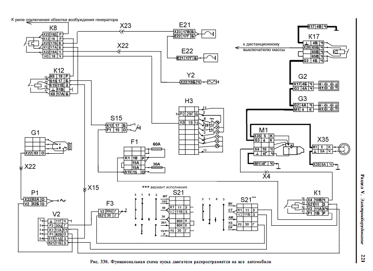
If the starter relay is not electronic, then there are no white wires to the starter relay. You, perhaps, supply power to the EPHU turn-on relay, so you have the EPHU limiting resistor warming up. Disconnect it by unplugging the connector from the relay. On KamAZ_akh, the starter blocking relay often fails. Through it, a control minus (brown wire) comes to the starter relay, and a control plus directly from the lock on. starter (green wire). To the starter, as he wrote samarik, there is a black wire from the relay. Here's a diagram. K1-starter relay, K12-relay incl. EFU, V2-starter interlock relay. Good luck.
Attached image (click to enlarge)
Profile
Group: Pros
Posts: 64
User #: 11516
On the forum since: 8/7/2008
Has warnings:
(0%)
Profile
Group: Old people
Posts: 1244
User #: 13406
On the forum since: 1.03.2009
Has warnings:
(0%)
Profile
Group: Old people
Posts: 405
User #: 12494
On the forum since: 12/11/2008
Has warnings:
(0%)
(097) 056-05-93, (099) 429-92-85, (093) 651-44-42
Repair of starters for agricultural and special equipment of domestic and foreign production (097) 056-05-93. We work all over Ukraine.
A sealed starter type ST142B with a capacity of 7.7 kW (10.5 HP) is installed on KamAZ vehicles.
Starter ST142B-3708000-10 is used on such equipment as KamAZ, KAZ 4540, LiAZ 5256, Ural 4320, Laz 4207, ZiL 4331, VT-100D tractor, PR-8M2 compressor station, Niva combine (with KamAZ engine), Yenisei combine 1200, Motor grader GS-14.02, KamAZ 55102, KamAZ 5511, KamAZ 5410, KamAZ 53212, KamAZ 5320. This starter has 24 volts, power 8.2 kW and 10 teeth.
Installed on engines KamAZ Euro 0, Euro 1, EURO 2, namely on such engines as KamAZ 740.30-260, KamAZ 740.31-240, KamAZ 740.35-400, KamAZ 740.50-360, KamAZ 740.51-320, KamAZ 740.52-260, KamAZ 740.53-290, KamAZ 740.37-400, KamAZ 740.38-360.
Starter ST142B-3708000-10 in different catalogs can be found under different markings such as ST-142B, ST142-10, ST-142B1, ST-142B2. Starter ST-142B-370800-10 has analogs that are completely interchangeable: starter 2501.3708-11 and starter AZF4554 (11.131.150) Iskra.
The starter shown in Figure 1 consists of an electric motor, a drive mechanism and an electromagnetic relay. It is installed on the flywheel housing on the left side of the engine. Remote control.
Starter technical characteristics.The rated voltage of the starter is 24 V, the voltage at a braking torque of 50 Nm is not more than 8 V, the switching voltage of the traction relay is 18 V, the no-load current at a voltage of 24 V is not more than 130 A.
The current at a braking torque of 500 Nm is not more than 800 A. Idling speed 5500–6500 min. The pressure of the brush springs on the brushes is 17.5–20.5 N. The height of the brushes is 19–20 mm.
Failed starters are sent to auto repair enterprises.
The starter motor is removed from the vehicle to be sent for repair. To remove the starter from the car, it is necessary to disconnect the "mass"; raise the cab; disconnect the wires suitable for the starter traction relay; disconnect the ground terminal from the starter; unscrew the nut and three bolts of the starter and remove the starter.
Starters coming in for repair may have the following malfunctions: when turned on, the starter does not work; the traction relay does not work (a characteristic click is inaudible); when the starter is turned on, repeated clicks of the traction relay and the impact of the drive gears on the flywheel crown are heard; the noise of the drive gears is heard; the drive gear does not systematically mesh with the flywheel crown during normal operation of the relay; the teeth of the drive gears are broken.
For repair, the starter is disassembled.
The technological process of disassembling the starter includes the following operations:
- unscrew the nuts on the relay cover and the starter housing;
- remove the jumpers between the output bolt of the traction relay and the exciter winding;
- unscrew the nuts securing the traverse (on the cover of the relay from the side of the collector);
- bend back the lock washers;
- unscrew the bolts and remove the cover from the manifold side;
- unscrew the screws securing the winding and brush leads to the traverse, remove the brushes;
- unscrew the screw on the adjusting flange and remove the lever axis;
- unscrew the screw from the side of the drive cover and remove the relay together with the armature;
- bend back the lock washers and unscrew the bolts;
- remove the cover from the drive side, remove the drive cover together with the lever and the drive;
- remove the thrust washer, remove the starter armature from the body.
Fig 1. Starter:
a - general view; b — control of the gap between the gear wheel and the drive sleeve when the starter is off; at the same. when the starter is on; 1 - cover from the side of the collector; 2, 14, 17 - bearings; 3 - traverse; 4 - jumper; 5 - contact bolt; 6 - relay cover; 7 — pin disc; 8 - stock; 9 - relay with coil; 10 - cover from the drive side; 11 — lever axis; 12 - drive; 13 - drive gear; 15 - drive bushing; 16 - lock washer; 18 - coils
After disassembly, the faulty starter windings are rewound on a winding rewind stand, after which they are impregnated with varnish to ensure insulation. The bent shafts rule the press. The bearings are replaced with new ones.
Assembly, running-in and testing of the starter. When assembling the starter, the pole coils are insulated with one layer of cotton, linen or taffeta tape, after which they are impregnated twice with insulating varnish GF-95 or PFL-8V and covered with gray glyphtal enamel GF-92-HS.
Before staging the coils in the starter housing, they are checked for the absence of turn-to-turn short circuits. The pole fixing screws are tightened with a press screwdriver. Before installation, the tapered surfaces for the pole screws in the housing are coated with NTs-OO-V putty.
The cover inserts on the manifold and drive side, as well as the intermediate bearing holders, are pressed in flush with the working planes. Burrs are not allowed at the point of entry into the liner of the lubrication holes. Before installation, the lubricating wicks are impregnated with 22 or 22 P turbine oil.
The surface roughness of the armature journals under the bearing shells and under the drive guide sleeve must correspond to Ra 0.63 µm.
The beating of the collector and the iron of the armature relative to the necks for the liners is allowed, respectively, no more than 0.05 and 0.15 mm. The roughness of the surfaces of the collector and the iron of the armature should be Ra 1.25 and 1.0 µm, respectively.
The armature collector must withstand the breakdown test at 220 VAC between the plates, and between the plates and the sleeve - 550 V.
When checking the armature on the PPYa device for turn-to-turn closures, a steel plate 0.5 mm thick, placed on the iron along the groove, should not vibrate. The frontal parts of the armature winding are bandaged with wire (from the collector side - 14-16 turns, from the drive side - 10-12 turns). The beginning and end of the winding of the band must be under the bracket. The bandages are soldered with pure tin. The anchor is impregnated with GF-95 glyphtal varnish, the iron surface of the anchor is covered with GF-.92 enamel. The anchor must withstand the spacing test at 10,000 min.
’For 30 seconds. After the test, individual collector plates shall not protrude more than 0.01 mm.
The insulating gasket is glued to the cover, from the collector's side with BF-4 glue. Insulation of insulated brush holders must withstand the 220 V alternating current breakdown test for 1 min. The relay armature must move freely without jamming in the coil frame. An additional stroke of the armature of 1.5-2.5 mm after closing the contacts is adjusted with washers on the rod.
The resistance of the shunt winding of the relay coil at 20 ° C should be equal to (2.5 ± 0.3) Ohm, and that of the serial one - (1.44 ± 0.2) Ohm.
When soldering the terminals of the coil, POS 40 solder is used, and when gluing the insulation, BF-4 glue is used.
When assembling the drive, all friction surfaces and spline parts are lubricated with CIATIM-203 grease. The contact surfaces of the starter relay must be clean and in the same plane with an accuracy of 0.2 mm. The contact planes and the contact disc must be parallel.
The surfaces of the armature shaft for bearings, ears, pins and the axis of the lever are lubricated with CIATIM-203 grease before assembly. When assembling, the cover from the side of the collector is placed with an edge opposite the outlet bolt located on the body. O-rings and washers are lubricated with CIATIM-201 or CIATIM-202 grease before assembly.
The brushes should move freely in the brush holders without jamming. The spring pressure on the brush at the moment of separation, measured along the axis of the brush, should be 15-20 N. When assembling and adjusting the starter, the recess of the adjusting disc must be not lower than the horizontal axis of the disc. The assembled starter is painted with XB-125 or XB-124 enamel.
When the starter relay is off, the distance (gap) between the drive sleeve end and the thrust washer should be 0.5-2 mm. The relay contact closure is monitored using a 24-volt lamp connected between the (+) battery and the starter relay output bolt.
When the starter relay is off and the gasket is installed between the end of the drive sleeve and a thrust washer 23 + 0L mm thick, the contacts should not close (the control lamp should not light up).
The axial clearance between the drive and the thrust washer is adjusted by turning the lever axis. The actuator must move freely along the shaft without jamming and return from the off position to the initial position after disconnecting the voltage from the relay terminals.
After assembly, the starter is checked for the reliability of the switching mechanism, the frequency of rotation of the armature, the noise of operation at idle and for tightness. In addition, the starters are tested for the amount of torque generated during full braking.
The test should be carried out on a stand that allows the drive to fully brake and measure voltage, current and torque.
The starter engaging mechanism should work flawlessly, during operation there should be no knocks and noises indicating the presence of malfunctions. The reliability of the starter engagement mechanism is determined by test engagement and inspection. The presence of knocks and abnormal noises is established by listening to the operating starter at a distance of 1 m.
The starting voltage of the starter relay must not exceed 18 V.The electrical characteristics of the starter are monitored at ambient and starter temperatures (20 ± 5) ° C.
When checking at idle speed, the starter with a voltage at the terminals of 24 V should consume a current of no more than 130 A 30 s after switching on.
When testing for full braking, the starter must develop a torque of at least 50 Nm, consuming a current of not more than 800 A. The voltage at the terminals of the starter during this test should be no more than 8 V. starter clamps.
The test of the starter for tightness is carried out in a special chamber with fresh water at room temperature by creating an increased pressure inside the starter using purified compressed air of 0.01–0.02 MPa. Increased pressure is created before the starter is immersed in water, the pressure is maintained for 1 min and it is removed only after the starter is removed from the water. To create the specified pressure inside the starter, a special casing is screwed to the flange of the drive cover through a rubber gasket.
After the starter is immersed in water, three starts are made at idle at a voltage of 24 V for 5 seconds each. The starter is considered to have passed the tightness test if there is no systematic release of air bubbles.
The technical condition of the starter is checked at the stand of model 532M.
Checking the technical condition of the starter at idle speed. To check the technical condition of the ST-142B starter at the stand, you must:
1. Install and fix the starter on the table and connect it to the stand, for which:
- lay the prism of the starter installation on the stand table;
- install the starter on the prism so that the flywheel drive gear is on the opposite side from the stand;
- connect the terminal (+) of the starter with the terminal "(+) СТ хх" of the stand;
- connect the (-) terminal of the starter with the “(-) CT” terminal of the stand;
- connect the terminals (+) and (-) of the batteries connected in series with the terminals of the stand.
2: At the stand itself you need:
- set the ammeter switch to the "ST 2000" position;
- set the voltage to 24 V;
- insert the tachometer shaft head into the center recess of the starter shaft;
- press the ST starter switch on button for 4-5 s; in this state, according to the tachometer arrow, determine the frequency of rotation of the starter shaft and according to the ammeter arrow - the power of the consumed current; the rotation frequency of the starter shaft should be 5650 - 6500 min-1, and the current strength - 130 A.
Checking the technical condition of the starter under load (checking the starter's performance). To check the technical condition of the starter under load, you must:
1. After checking the starter at idle speed, additionally install: - on the bench table - a hydraulic dynamometer;
- onto the gear wheel of the starter flywheel drive - the grips of the dynamometer lever, then squeeze them with a screw, turning the handle;
- support the dynamometer lever on the hydraulic dynamometer rod.
2. Switch the wire from the (+) starter from the terminal of the stand "(+) CT xx" to the terminal "(+) st. torm "stand.
3. Set the ammeter switch to the "CT 2000" position.
4. Press the starter button "ST" for 2-3 s and record the dynamometer readings and the current strength.
The maximum starter torque should be 7.7 kW (10.5 HP), and the amperage should not exceed 800 A.
Acceptance of starters by the Quality Control Department is carried out during or after testing by external inspection, listening to their work and monitoring their performance.
At the same time, they check:
- completeness in accordance with the drawings;
- lack of mechanical damage;
- pressure of the brush springs on the brushes, which should be 17.5–20.5 N at a brush height of 19–20 mm, operation noise;
- compliance of the performance characteristics of the starter with the above technical requirements.
Suitable starters, accepted by the Quality Department, must have an acceptance stamp.
For repair of the ST-142B (KAMAZ) starter, please call (097) 056-05-93.
Starter repair ST 142 kamaz
Starter repair ST 142 KAMAZ
Solenoid starter relay ST142 Kamaz. Repair.
Assembling the Starter CT142 Kamaz and checking it
Starter ST 142 Kamaz. Repair. One of the faults.
Dismantling of the Starter CT142 Kamaz
KAMAZ MASTER, starter repair.
Starter ST-142 (Kamaz) does not work. We are looking for a reason. Repair.
Replacement of starter bushings ST-142 (Kamaz)
- DIY starter repair - how to do it?
- 1. Do-it-yourself starter repair begins with dismantling.
- 2. How to repair the starter if it stops working?
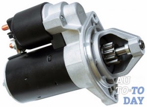
In addition, the maintenance and repair of a car is quite costly. Therefore, your own skills will also help you save a considerable amount of money. At the very least, you need to deal with the most basic operations. One of these operations is starter repair.
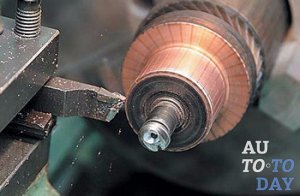
1. Solenoid relay - designed to synchronize the entire starter. When the driver turns the ignition key, current is applied to the relay and forms an electromagnetic field. After that, the relay rotates the on lever and clings to the flywheel gear. Then the current flows to the starter windings.
2. Anchor - designed to rotate the bendix gears. When the engine starts, the armature returns to its original position using a return spring and opens the contacts.
3. Bendix (freewheel) - needed to control the speed of rotation of the shaft. The drive shaft must rotate faster than the driven shaft.
4. Brushes and brush holders - are intended to supply voltage to the armature plates. They also increase engine power.
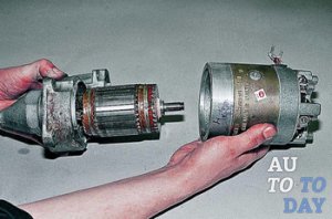
1. Raise the bonnet.
2. Turn the ignition key (you can ask someone to do this).
3. Listen and determine where the buzzing is coming from. It is in that place that the starter is located.
Since the starter is located in a very inconvenient place, in order to remove it, you will need a lot of patience and a set of automotive tools (different wrenches, including those with flexible extension cords). It is best to dismantle the starter in the inspection hole, since without the inspection hole it will be very difficult to move under the vehicle. Steps for dismantling a car starter:
1. Disconnect all battery terminals.
2. Unbolt electrical cables that conduct current from the solenoid pins and from the terminals on the starter.
3. Remove engine cover.
4. Tighten the lower and upper nuts securing the starter to the engine compartment.
5. Remove starter.
Why is it necessary to remove the starter from the car?
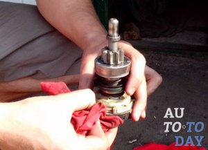
During its operation, the starter becomes very dirty due to its location and the use of graphite brushes. So whether you managed to find a breakdown in the starter or failed, in any case, you need to thoroughly clean the starter itself and all its parts from contamination, and also check the integrity of all components (especially the windings). And only after such manipulations can you start reassembling and reassembling the starter on the car. The starter is mounted in the same steps as dismantling, only in the reverse order.
The service life of an automobile engine is much longer than that of a starter. So, whatever one may say, sooner or later the starter will have to be repaired or changed, and you need to be ready for this. But you shouldn't rush to completely change the device. After all, firstly, the reason may not even be in it (but, for example, in the battery or flywheel). And, secondly, it will be much cheaper to repair the starter.
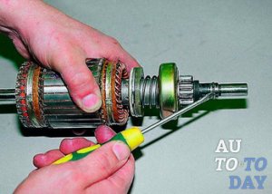
The most common starter breakdowns:
1. Breakage of the starter retractor relay. Because of this, the bendix gear will not feed to mesh with the flywheel splines.
2. The wear of the graphite brushes, with the help of which electricity is transmitted to the armature, as in many electric motors (in fact, the starter is the electric motor). And over time, graphite brushes try and there is a need to replace them.
3. Starter bearings worn. This can be diagnosed by strong vibrations and destruction of the rest of the starter mechanism, although the starter will continue to work.
To check the functionality of the removed starter, a charged battery must be used. The mass is connected to the case, and the positive wire is searched for malfunctions. When the "plus" is connected to the contact of the solenoid relay, it should work and extend the bendix. If the retractor relay does not work, then it will need to be replaced or repaired (malfunction in the retractor relay). In most cases, it will be necessary to replace the solenoid relay, since most of these devices are non-separable.
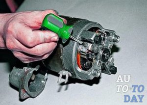
When the starter is operating, the greatest load falls on the bendix gear teeth, which are in engagement with the flywheel teeth. Therefore, after several years of car operation, these teeth are simply erased and become the reason that the engine cannot be started or it starts irregularly. This problem can be solved only by completely replacing the bendix gears or the flywheel crown.
Remember, very often the reason for the inoperability of the starter is the contamination of the contacts of its constituent parts. So keep a close eye on the cleanliness of both the starter and all other components of your vehicle.
At the first suspicion of a malfunction, do not postpone the repair of the starter on your car, since without this element you can simply stop somewhere in the wilderness and it will be extremely difficult to get out of there on your own.
| Video (click to play). |

