In detail: do-it-yourself repair of a Chinese scooter starter from a real master for the site my.housecope.com.
It's easy to start the scooter motor: press the button that activates the scooter's electric starter. But what if you press on her, but all to no avail? Or if the crankshaft rotates, but at the speed of a wind turbine?
Don't play guessing game
The simplest thing is to contact a friend who owns the same type of "stool", and to check, replace your starter with a working one. If there is such a friend. If not, you will have to strain your own convolutions: the starter is not a burned out bulb in the turn signal. Usually the reason for inaction is a "glitch" in his electrical circuit. How to check each joint and insulation, Moto wrote in # 7-03. And if the reason is different? The launcher needs to be repaired.
How does it work? This is a type of DC motor: inside the case there is an armature, a brush assembly and a stator (see illustrations). An anchor is a group of windings (coils) evenly spaced around a rotating central shaft. They are connected to a cylindrical “nozzle” on the shaft (manifold), made up of numerous copper plate segments isolated from each other and from the shaft. Two copper-graphite contacts are pressed to the segments - brushes, through which voltage is applied to the windings. Two permanent magnets (stator) are fixed inside the starter housing, they form a magnetic field, which makes, in fact, the armature rotate.
It happens like this. Press the button - supply "plus" of power to one of the brushes (the second is permanently connected to the "minus" through the scooter frame). As soon as the current appears in the armature windings, the steel cores of the coils are magnetized; the wire is wound in such a way that the armature field "repels" from the stator magnets. The shaft has nowhere to go - it will turn and the brushes will come into contact with the next pair of armature segments. Then the process will be repeated. It's like a swing: swinging it, you increase your speed and energy with each next swing. At first it is easy to stop your pitching, but soon, try, get in the way - you will fly away! So the baby starter, having unwound, manages to move and rotate the crank.
| Video (click to play). |
An example of twisting the wire of the brush: A - correct; B - too tight
twisting can impede free movement of the brush.
Now determine what is hindering this. Dismantle the starter and clean it from the outside (usually it is located so that there is enough dirt on the housing). Unscrew the screws securing the stator. Now - attention! While removing the housing, firmly hold the armature shaft in the front cover. The static magnets are extremely strong - if they drag the anchor behind them, the brush assembly may be damaged (at least, you will lose the springs of the brushes, and try to find a replacement for them). Therefore, having correctly "dismembered" the starter, carefully remove the anchor from the cover. Disassemble the brush assembly, but do not touch the positive contact and its current lead - it is firmly embedded in the cover. Wipe all parts of the starter with a swab dipped in alcohol - that's it! Acetone gasolines and similar solvents will damage the plastic in the structure and the insulation of the armature windings. And do not leave a single gram of dirt inside the starter: this is dust from the production of brushes, and it is conductive. If you miss it, it’s not even an hour for yourself to inflict a leakage of current, or even a short circuit.
Make sure that all parts are intact and in good working order: the brushes at the edges are not broken off, freely, but without distortions, move in the guide wells, the height from the working surface to the wire is at least 3 mm. Grasping the wire and brush, pull slightly on the assembly - rarely, but it happens that they are poorly fastened to each other.It is simple to regain strength: drop a mixture of Moment glue and powder from a pencil lead into the hole of the brush - and you can insert the wire into place. Stumbled upon contacts that have served their purpose? It doesn't matter either! In their place, it is permissible to implant brushes, for example, from a drill (sharpen the dimensions to the desired size). When choosing a "donor", the main thing is that the diameter of its collector is close to the starter one. This dimension determines the hardness (read - wear resistance) of the contact material. When mounting the brushes in places, do not twist their wires too tightly, moreover, loosen them a little so that they do not stand with a stake and do not interfere with the movement of the brush in the guide.
The springs, of course, must be intact, the coils must not be jammed. The height of the "spiral" is at least 9-10 mm. You can "cheer up" the hooked on a few millimeters by slightly stretching the turns. But it is safer this way: stick a plastic gasket on the spring support (thickness - shrinkage size). To replace the broken part, if it is not possible to find the original, wind it from the spring of a ballpoint pen. You will have to tinker: make a blank for winding, before starting work, anneal the wire on fire, and heat the finished part again and cool it in engine oil.
Begin checking the rotor by inspecting the windings. The coils are blackened, the insulation is charred and there is a pungent smell of burning - that means the anchor is "over". Sadly, if you don't find a replacement (a new or used working part), you are in for a replacement starter.
Another possible damage, outwardly indistinguishable, is a breakdown of the insulation of the windings to ground. An indirect sign: with a working battery and power circuit, the starter barely rotates the crankshaft. The test method is as follows: a 220 V control lamp should not light when connected to the network through any collector plate and armature shaft. But if you are not an experienced electrician, entrust the test to a specialist. "Two hundred and twenty" for the eyes is enough to kill an elephant! Don't leave the scooter an orphan.
Have you safely passed this stage? This means that the lethargy of the starter is hidden in the oxidation (burning) of the collector. Take a fine-grained glass-coated skin, wrap a knot with it and remove the damaged layer of metal with smooth (circular and without pressure!) Movements. It is unnecessary to bring the surface to the “mirror”, it is enough if there is no roughness of more than 0.3 mm on the segments.
There is also something else: the knocked brushes envelop the metal of the segments on top of each other and ultimately close the windings with each other. Well, remember what determines the speed of the anchor spin? That's the same - the number of coils! "Put them back in place" by cleaning the spacer grooves. If you notice that the collector is swinging on the shaft, be sure to fix it with a drop of glue (of the same "Moment"), otherwise the wires of the coils will soon break off.
It remains to check the "strength" of the stator magnets: insert a steel rod inside the housing, say, a screwdriver. If it is not at all easy to keep it in the center of the hole (it immediately sticks to the magnets) - order.
Having replaced or normalized the worn out, assemble the motor in the reverse order. Operate carefully with the brush assembly: with elastic plates (thickness 0.4-0.6 mm), sink both brushes into the wells to the maximum and insert the collector into place along these "guides", but without pressing. If the devil pulls you to "tap" the anchor, prepare new brushes! Lubricate the "tail" of the shaft, opposite the collector, with refractory grease, but only a little. And pay attention to the body-to-cover gasket. At the slightest hint of a loose joint, replace the seal, otherwise everything that has been "licked" inside will soon be clogged with road dust.
I advise you to carry out the "output" control of the repair: fasten the starter in a vice (do not hesitate!) And connect it to the battery through an ammeter. The idle current (this is how this operating mode is called) should be in the range of 6-7.5 A. Now block the rotation of the armature (do not damage the gear teeth!) And turn on the starter for a couple of seconds. The current should rise to 16-18 A.A significant deviation from the given value in any direction will mean that you "yawned" one of the described faults. Find and eliminate it.
In addition to the electric motor, there is also a mechanical part in the starter, it is called an overrunning clutch. Its purpose: firstly, to transfer torque from the armature to the crankshaft - this is performed by a gear pair. Secondly, after starting the engine, disconnect the armature from the crank. The starter is designed for short-term operation (no more than 10-15 seconds for one activation). Continue to rotate the running scooter motor - the starts will fall apart in a matter of minutes. In order not to run into something like this, make sure the clutch is working properly. Remove it from the starter housing (if it is an 80-90 scooter) or from the variator compartment (modern model). Rotate the pinion counterclockwise - it should move along the shaft (axially) without jamming. Release the gear - a working clutch is "obliged" to return to its original position without delay.
And one more thing: shake the clutch - nothing should rattle inside. Having noticed any of this, disassemble and fix the mechanism. Slightly unclench and remove the retaining ring, then the support washer and the return spring with supports. Unscrew the gear from the shaft. Malfunctions can be caused by: contamination of the shaft and gear teeth, crushing or breakage of the spring, jamming of the centrifugal mechanism. You already know how to "treat" a spring. Remove the "stale" grease with a solvent (acetone, gasoline, etc. are suitable here), use a consistent and refractory one as fresh. The damaged spring "ring" of the centrifugal unit can be replaced with a similar one of a similar diameter, borrowed from an automobile oil seal. When reassembling, make sure that the retaining ring is firmly seated in the groove in the shaft and is "closed" by the support washer.
And a special case of starter powerlessness. The overrunning clutch, installed in the variator compartment, can stop the rotation of the electric motor if it itself gets jammed by the compartment cover. Oh, often would-be mechanics forget that between the cover and the crankcase there should be a gasket of the prescribed thickness, and not absent at all. The editors would like to thank the Moto-Help technical center, Moscow for their help in preparing the illustrations.
Checking the insulation of the armature windings (A), cleaning the collector (B), the circuit for checking the insulation between the segments and the ground (C).
Disassembly and repair scooter starter
With a habitual movement, he turned the ignition key, pressed the starter button ... And silence. I repeated the launch - starter does not plow.
If, after pressing the starter button, you hear a short, unusual grinding noise and the engine does not start, then most likely the matter is not in the starter - the battery is simply dead. Symptoms of a starter malfunction are different: when the start button is pressed, a single metallic click of the contacts of the starter relay is heard, but the noise of the motor does not follow. What should I do?
Engage first gear and with the clutch depressed, pushing the motorcycle back and forth, press the starter button. If the motor starts working, we can conclude: there is poor contact between the carbon collector brushes and the collector. Dust got between the rubbing parts (collector brushes), because of it sparking occurred and a kind of dielectric was formed. When the motorcycle was pushed back and forth, when sliding the brushes found contact - and the starter started working.
This way of starting a motorcycle will help out if the "illness" is at an early stage. However, a moment will inevitably come when the motor cannot be excited.
Let's consider the repair of a failed starter using the example of the Honda XR250 Baja. Fortunately, there is no cladding on the motorcycle, and the part we are interested in is easily accessible (photo 1).
For work you will need: keys - end keys "for 12" and "10", open-end keys - "for 7" and "10". Place the unit on the stand. To get to the starter, dismantle the exhaust pipe. To do this, unscrew the four nuts on the pipe flanges (photo 2, 3).Just loosen the bolt on the clamp.
Unscrew two bolts of the oil line and fastening the starter housing to the crankcase (photo 4). Disconnect the terminal on the starter. Lightly tap with a hammer (through a wooden block) the starter housing (photo 5) - so that the splines of the armature shaft disengage with the overrunning clutch gear (photo 6). Pull the starter out of the frame through the left side.
Opening the starter. Remove the two bolts (Photo 7). Both housing covers are removable, the armature easily comes out of the rotor (this is a permanent magnet). Be careful and prudent: do not confuse the order of the washers on the armature shaft!
In photos 8 and 9, dirt is clearly visible, which finished off the starter of the "unkillable" Honda: the collector was covered with a dielectric, the slats (slots in the rotor) were clogged with dirt, the collector brushes hardly move in the nests.
Repair. Sand the collector with sandpaper (grain size - fine), clean the lamellas with a scraper made from a hacksaw blade (photo 10). Wash the anchor in clean gasoline (photo 11). Also "bathe" the housing cover with carbon brushes, treat it with fresh gasoline and the needle bearing in the other cover especially carefully (photo 12).
Assembly. The needle bearing is lubricated with engine oil while the motor is running, but when reassembling, lubricate it with the same engine oil anyway. A sintered bushing is installed in the housing cover on the side of the brushes - fill it with grease (Castrol LMX).
Connect all the parts - washers, O-rings (install them in the order in which they are laid out in photo 13). Do not confuse which side the stator housing is joined to the cover in which the brushes are located; for this there is a special groove on the housing (you can see it in photo 9) and a counter protrusion on the cover (it is in photo 8). If the sealing rubber ring (there should be two of them) on the stator housing is torn, but there is no replacement, you can use a sealant (and we had to use it). Bolt the starter parts together. Check if the anchor is scrolling in the hull? Is nothing jammed?
Install the starter motor to the motorcycle. Carry out all operations described in disassembly in the reverse order.
A detailed description of the removal and repair of a starter on a 4-stroke 50 cc engine 139qmb scooter Super Sport Acar
If the scooter does not start from the electric starter, then you can quickly check its serviceability as follows. It is necessary to connect directly the positive wire to the starter itself and the negative wire to the starter body (for complete confidence, in order to exclude current losses somewhere in the circuit). If the starter is "silent" - you need to remove it.
Accessing it on the engine 139qmb scooter Super sport acar can be called free. You will need a socket wrench (short) or a cap wrench for 10 because the bolts can stick a little, as I did. First you need to disconnect the plug from the starter relay,
then unscrew the two bolts (a black negative wire is suitable for the left one) and, swinging it a little by hand, remove the starter from the engine block socket. Difficulty retrieval is usually caused by the rubber sealing ring, which should preferably not be lost. In the future, the wire can be disconnected from the starter (or you can simply remove the terminal from the starter without disconnecting the plug, but as it turned out later this is not the best option) by grasping the terminal with your fingers and pulling it out of the socket a little.
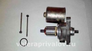
Then unscrew the two thin long screws that fasten the halves of the starter and, having slightly separated, pressed the rotor in order to remove it together with the front part, where the brushes are located.
Then you can remove the rotor from the housing with brushes.
By external examination we determine the condition of the brushes and the rotor collector. In my case, everything was all about cleaning the brushes and the rotor manifold with sanding paper number 0. There was a slight soreness and slight wear on the brushes, but not so critical that it could be changed. After grinding the rotor and brushes, I washed everything in clean (oil-free) gasoline, dried it and assembled it in reverse order.The first assembly took quite a lot of time due to the complexity of the installation of the brushes and the rotor ... I had to come up with a device to hold the brushes. The brackets should not be made of too thick wire, but it is better to make them from plates or use special clamps.
After the complete assembly of the starter, as a result, it began to work.
Entering text symbols of smiles (such as - 🙂 and 😛) into the message are automatically converted into pictures (there must be a space before inserting - you can copy and paste).
EXAMPLES:
🙂 smiling 😀 laughing out loud :-))) laughing 🙁 Confusion or discontent
:-|| Angry, angry 😉 winking 😛 showing tongue : clap: bravo, clap your hands
➡ Bang your head against the wall.
And also you can use these HTML Tags and attributes for your comment:
If at one fine moment the starter refuses to start the engine, do not be discouraged, perhaps it can still be brought back to life. In most cases, the starter motor fails due to various types of dirt or wear on the brushes, even beginners can eliminate all these problems.
In order to be sure that it is the starter that is faulty and does not "want" to turn the engine, you can connect it directly to the battery (the battery must be charged), if the picture has not changed the starter is silent or turns bad, then the reason is in it.
It happens that during repairs on some scooter models they forget to put a gasket between the variator cover and the engine, thereby clamping the overrunning clutch (bendix), which leads to weak rotation of the starter, in order to eliminate this moment, loosen the bolts on the cover and try to start the engine, if the picture has not changed, then the reason is the starter.
Today we will consider such a starter, read about where the starter is and how to remove it here.
In order to disassemble the starter, we need to unscrew the two bolts on the starter cover and, holding the shaft with your hand, carefully remove the cover.
There are two permanent magnets inside the cover
After removing the shaft from the body, the first malfunction was discovered: one brush turned out to be broken off and its fragment was inside the body in the photo highlighted in red.
Second malfunction: severe wear of the brushes.
The third malfunction: severe contamination of the rotor collector, in order to eliminate this malfunction, we need to clean out all the dirt between the collector lamellas with a needle and then grind the collector with sandpaper.
Here's what you should end up with.
Next, we rinse everything well, preferably with alcohol, put new brushes (when installing new brushes, do not forget to correctly insert the wiring into the special grooves in the housing), lubricate the bushings in which the rotor rotates with refractory grease and assemble the starter.
After assembling the starter, it is advisable to check it, for this: we connect the starter through an ammeter to the battery and look at the idle current, it should be approximately the same as in the photo. The no-load current for different models of starters can differ significantly.
If, after all that has been done, your starter is bad, rotates, heats up, the idle current is too high, then most likely the rotor is faulty, which can be changed to a new one or rewound.
Never use corundum sandpaper to clean the collector. Glass only. In the theory of electrical devices, this point is specially stipulated - the electrical contacts are copper, silver cannot be cleaned with corundum cloth. Better with a file, a file, but not corundum. Corundum will enter the copper of the collector and will remain there forever, abrading the brush. This phenomenon is similar to dropping soap into sand and trying to rinse it off. At the lectures on electrical devices, the teacher explained this to us with a convincing example: at the Arsenal plant, for the manufacture of lenses for objectives, a long glass cylinder was cut into thin discs with a copper circular saw without teeth, but its rim was sprinkled with diamond chips. As the disk wears out, decreases its diameter, the density of the diamond at the periphery of the disk increases - diamond chips were not removed, but “moved” to the center. As a result, cutting even improved.
If you are going for best contents like I do, just pay a
visit this site everyday for the reason that it offers quality contents, thanks
when removing the starter from the chain Chinese, the oil must be drained.
This site uses Akismet to combat spam. Find out how your comment data is processed.
If there is any suspicion of a malfunction of the starter, I immediately remove it from the engine and throw it in the trash. I simply do not have time to repair such small things. Especially when the motorcycle season is in full swing and everyone needs to quickly be repaired and go about their business.
But, in especially rare cases, I still undertake the repair of starters when a rare model of a scooter comes across for repair for which it is difficult to find spare parts or when several faulty starters accumulate from which I then collect one.
By itself, repair or diagnostics does not present any particular difficulties, even for a beginner. And it will mainly consist in disassembling, washing, checking, cleaning the working surfaces of parts and assembling. But we will not be in a hurry with the repairs. Let's start with general questions, and touch on the topic of repair at the very end of the article.
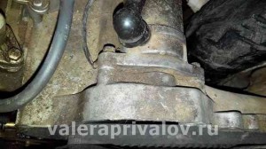
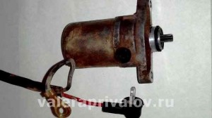
Finding a starter on a scooter engine is very simple: remove the front plastic engine hood and seatpost, inspect the engine and find on it a small cylindrical part (approximately the same as in the photo) located perpendicular to the longitudinal axis of the engine to which a thick power wire fits - this will be the starter.
On most scooter models, the starter is mounted on top of the engine just behind the cylinder. In rare cases, the starter is installed in front or below the engine.
If, when you press the start button, the starter does not turn, then this situation cannot always tell us about its malfunction. In addition to the starter itself, there are several elements in the scooter electrics that control its operation. Such as battery, relay, start button and power supply wires. And if at least one of these elements fails, a fully serviceable starter will not work.
Therefore, in order not to waste a lot of time and then do unnecessary work, we will not guess, but will act easier: we will go by the method of exclusion: we will connect the starter directly to the battery - bypassing the relay, the start button circuit and the standard power wires, thereby completely eliminating malfunctions in the elements responsible for the operation of the starter.
Without removing the starter from the engine - we are looking for a power terminal on its case and disconnect the wire from it. We remove the battery (charged) from the scooter, look for, ask someone or buy two pieces of thick copper wire. We connect the wires to the battery terminals. Then, the wire coming from the negative terminal of the battery is applied to the starter case, and the second wire - coming from the positive terminal of the battery - is applied to the starter power terminal
- If the starter starts working, then it is fully functional and the cause of the malfunction must be looked for in the relay, start button or wires supplying power to it.
- If the starter does not work, then the malfunction lies in itself and it must be removed, disassembled and checked. It is possible that it can still be repaired and save a lot of money.
After we found the starter and provided free access to it, we look for a terminal on its body to which the power wire fits and unscrew the wire from it. Then, we determine where the starter is attached to the engine housing, unscrew the mounting bolts and take it out of its seat.
Mounting bolts, in this case they are located at the end of the body
In this case, the starter is flanged and its mounting bolts are located at the base of the housing.
To facilitate dismantling, on some engine models, there is a special technological gap between the starter housing and the engine housing (depending on the engine model). We insert a flat screwdriver into it and loosen the starter with it.
In the starter device, in fact, there is nothing new and complicated since the time the DC electric motor was invented.Which he actually is.
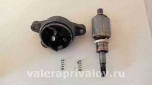
Inside the body there is a movable cylindrical element called a rotor (collective farm - an anchor). An insulated copper wire is wound on the rotor in a strictly defined order, which forms several independent coils, circuits, windings, poles, circuits - which, in fact, are the same. The ends of each of the coils have their own independent outputs in the form of lamellas (contacts) on the collector.
Inside the main body, two permanent magnets are glued in, exactly enveloping the rotor. Each of the magnets has a different pole N (north) S (south) in relation to each other. Those who studied at school will understand ...
After you press the start button, the electric current from the battery will begin to pass through the power terminal, the brush, and then, passing through the lamellas of one and the rotor windings, it forms a constant magnetic field along the axis of the armature.
I think there is no need to explain that the magnetic field that generates a constant electric current has different polarities? So that's what I mean. Oh yes, the magnetic field of the rotor will begin to interact with the magnetic field of the permanent magnets and the armature will deflect by a certain degree. The collector will turn, the next pair of lamellas will come up to the brushes and the rotor will deflect again. Thus, it will rotate exactly until you lower the start button.
There is nothing special to break in the starter, and all its malfunctions consist in wear and tear, hanging brushes and contamination of the collector, which often happens due to engine oil entering the housing from the engine crankcase. It is worth noting that malfunctions associated with collector fouling and brush wear are typical for DC electric motors.
Worn brushes, as well as a dirty collector, prevent the passage of electric current through the brushes to the rotor winding lamellas, and therefore the starter stops working. In this case, to restore the starter's performance, we just need to clean and wash the collector and replace the brushes with new ones or make them ourselves (more on that later).
In addition to purely mechanical malfunctions associated with wear and contamination of conductive elements, there are a number of malfunctions associated with a short or interturn circuit of the rotor windings, as well as with a breakdown in the contact of the output of the windings with the collector lamella and burning of the wire insulation.
All these malfunctions are characterized by increased noise and heating of the starter during operation and a drop in its speed. If, after cleaning the collector and replacing the brushes with new ones, the starter does not turn well, heats up, buzzes, then most likely not everything is in order with the rotor windings. Either they shorted, struck the ground, or simply burned out. And there's nothing you can do about it.
We turn off the bolts tightening the body, there may be two of them, or maybe more, depending on the design. We pinch the shaft protruding from the body with our fingers and disconnect the halves of the body as carefully and slowly as possible.
We take out the rotor from the body and carefully inspect the collector and brushes. If the collector is dirty, then it must be cleaned and washed with clean gasoline.
Brushes in normal condition should be no shorter than 5-6 mm.
We put the rotor on some clean surface, preferably wooden, and use any suitable needle to clean out the dirt between the collector lamellas.
After stripping, we take a piece of some non-fluffy cloth, moisten it thoroughly in clean gasoline, wrap it around the collector and begin, as it were, to scroll the rotor collector in it. It is not necessary to rub the collector heavily, it will be enough just to wash it from dirt to approximately the same state as in the photo.
There are no problems with the rotor collector: they cleaned it, washed it dry and that's it.But what about worn-out brushes? They are not on sale and have never been, and a new starter is very expensive, what should I do? There is a way out: to make the brushes yourself, or rather not to make, but to remake from others.
For the manufacture of new brushes, a set of new brushes for the dynastarter of the Soviet motor scooter "Ant" is ideal for us. Such a kit costs only 150 rubles and includes two pairs of brushes, enough for exactly two starters. You can buy such a set at any store that sells spare parts for Soviet motorcycles. Why exactly from "Ant", and not from a drill, for example? Because ant brushes are designed for high current and very resistant to abrasion, and brushes from ordinary power tools are soft and quickly burn and wear out.
We take a brush, it is initially much larger than the original one and we grind it on all sides on emery so that it calmly goes into the nest and at the same time does not really hang out there. Ideally, you should try to grind the brush so that it sits in its nest as tightly as possible and at the same time walks in it without the slightest, even barely perceptible resistance.
We insert our freshly turned brush into the nest and check its mobility without fail.
We solder the wire of the homemade brush to the power terminal
We put our homemade brushes in place.
That's the whole secret and most importantly - with such home-made brushes, besides worth a penny, you can completely restore the starter's work. And for many, many seasons. And this has already been tested on more than one copy. At least I have never received any complaints about the operation of the starter with the brushes from the "Ant" implanted in it.
In order not to puff up for a long time and tediously with the installation of the rotor in the body - fix the brushes from extending in their nests with toothpicks, lubricate the rotor axis with some refractory grease, install the rotor in the body and remove the toothpicks. It will be much easier and faster this way, and most importantly, you won’t break or collapse anything.
And one more thing: if, after assembly, the starter will rotate in the other direction, do the following: unscrew the bolts tightening the case and turn the case with magnets 180 degrees relative to the second half of the case and the problem will go away.
How to remove the driven gear of the scooter starter (for example, Honda Lead)
The peculiarity of the location of the driven starter gear on the Honda Lead scooter makes it impossible to simply remove it if necessary.
The gear is put on the crankshaft, which has a tapered cut at the press-in point. While tightening the variator nut, the gear is pressed into the shaft even more, after which it is almost impossible to remove it with improvised means. Even if you can do it, there is a very high chance of bending the crankshaft.
So, what this gear looks like and how to remove it correctly, we will consider further. After you have unscrewed the variator cover and the variator nut itself (and we have already examined how to do this), you can easily remove these parts.
1. Crankshaft. 2. CVT (movable cheek). 3. Driven starter gear.
Unlike the Honda Dio and Honda Tact scooters, on the Honda Lead scooter (which we are reviewing now), the gear is mounted behind the variator. On the Dio, for example, it is installed at the front and at the same time is the fixed cheek of the variator.
Fixed cheek piece of the Honda Dio scooter variator. At the same time it is a driven starter gear.
This layout will be the prototype for most Chinese scooters.
But back to the Honda Lead scooter (the AF-20 or HF-05 model is being considered) with a 50 or 90 cc engine.
To remove the gear, we need a special puller.I repeat once again, do not try to remove it with improvised means, bending the crankshaft or ruining the bendix is very simple.
Why mess up? Yes, because there are super masters who try to remove it without removing the driven gear, hence the problem.
The puller can be of different layouts, it all depends on your imagination, but the principle of its operation in this case is the same. There should be an emphasis on the crankshaft (the same, preferably under the influence of 4 rods at once, which will go into the gear), as well as the capture of the gear through special holes. The holes are made in such a way that it can be easily gripped by the caps on the rods.
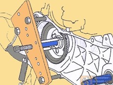
So, how to make this very puller. I will give an example of two options. Option 1 is a plate that has 3 holes for connecting to the crankcase, 4 holes for screwing in the rods, which will subsequently grip the gear, and the shaft itself, which is put on the crankshaft and tightens the gear when rotating. The fixation to the crankcase should not be rigid, it should be floating and is only needed for a uniform position of the plate. More details are shown in the figure:
Next, we will consider the second option of the puller.
The rods (2) are screwed into a round plate, which on the other side is nut-shaped and screwed onto the shaft (3). The plates at the ends are mushroom-shaped to grip the gear. The third part of the puller is the nut (1), which is screwed onto the crankshaft of the scooter and protects its threads from damage and reliably fixes the puller shaft during rotation.

 We insert the guides into the holes, place emphasis on the crankshaft, turn the puller nut and the gear in our hands.
You can also check out other articles on the topic:
Dedicated to all owners of Chinese scooters ...
To begin with, I would like to present the wiring diagram of a Chinese scooter.
Since all Chinese scooters are very similar like Siamese twins, their electrical circuit is practically the same.
The circuit was found on the Internet and, in my opinion, is one of the most successful, since it shows the color of the connecting conductors. This greatly simplifies the diagram and makes it more comfortable to read.
(Click on the picture to enlarge. The picture will open in a new window).
It is worth noting that in the electric circuit of the scooter, as well as in any electronic circuit, there is common wire... For a scooter, the common wire is minus (–). The common wire is shown in the diagram. green color. If you look more closely, you will notice that it is connected to all the electrical equipment of the scooter: the headlight (16), turns relay (24), dashboard illumination lamp (15), indicator lamps (20, 36, 22, 17), tachometer (18), fuel level sensor (14), sound signal (31), rear light / brake light (13), starting relay (10) and other devices.
First, let's go over the basic elements of a Chinese scooter circuit.
Egnition lock (12) or "Main switch". The ignition switch is nothing more than a conventional multi-position switch. Despite the fact that the ignition switch has 3 positions, only 2 are used in the electrical circuit.
When the key is in the first position, it closes Red and black the wire. In this case, the voltage from the battery enters the electric circuit of the scooter, the scooter is ready to start. The fuel level indicator, tachometer, sound signal, relay-turns, ignition circuit are also ready for operation. They are supplied with voltage from the battery.
In the event of a malfunction of the ignition lock, it can be safely replaced with some kind of switch like a toggle switch. The toggle switch must be powerful enough, because the entire electrical circuit of the scooter is, in fact, switched through the ignition lock. Of course, you can do without a toggle switch, if you limit yourself to closing red and black wires, as the heroes of Hollywood action movies once did
In the other two positions, the black and white wire from the CDI ignition module (1) to the body (common wire). In this case, the engine is blocked.... Some scooter models have an engine stop button (27), which, like the ignition lock, connects the whiteblack and green (common, frame) wire.
Generator (4) generates alternating electric current to power all current consumers and charge the battery (6).
5 wires leave the generator. One of them is connected to a common wire (frame). An alternating voltage is removed from the white wire and fed to a relay-regulator for subsequent rectification and stabilization. WITH yellow wires remove the voltage, which is used to power the low / high beam lamp, which is installed in the front fairing of the scooter.
Also in the design of the generator there is a so-called Hall Sensor... It is not electrically connected to the generator and there are 2 wires from it: white- green and red –black... The hall sensor is connected to the CDI ignition module (1).
Relay-regulator (5). The people may call it "stabilizer", "transistor", "regulator", "voltage regulator" or simply "relay". All these definitions refer to one piece of hardware. This is what a relay regulator looks like.
The relay-regulator for Chinese scooters is installed in the front part under the plastic fairing. The relay-regulator itself is attached to the metal base of the scooter in order to reduce the heating of the relay radiator during operation. This is what a relay regulator looks like on a scooter.
In the operation of a scooter, the relay-regulator plays a very important role. The task of the relay regulator is to turn the alternating voltage from the generator into a constant one and limit it to 13.5 - 14.8 volts. This is the voltage required to charge the battery.
The diagram and the photo show that 4 wires are leaving the relay-regulator. Green Is a common wire. We have already spoken about him. Red - this is the output of a positive constant voltage of 13.5 -14.8 volts.
By white AC voltage from the generator is supplied to the wire to the regulator relay. Also connected to the regulator yellow wire coming from the generator. It supplies the regulator with alternating voltage from the generator. Due to the electronic circuit of the regulator, the voltage on this wire is converted into a pulsating one, and is supplied to powerful current consumers - a low and high beam lamp, as well as a dashboard backlight lamp (there may be several of them).
The supply voltage of the lamps is not stabilized, but is limited by the relay-regulator at a certain level (about 12V), since at high speeds the alternating voltage supplied from the generator exceeds the allowable one. I think those who have burned out dimensions when the relay-regulator malfunctions know about this.
Despite all its importance, the device of the relay-regulator is rather primitive. If you dig out the compound that is poured into the printed circuit board, you can find that the main relay is an electronic circuit from a thyristor BT151-650R, diode bridge on diodes 1N4007, a powerful diode 1N5408, as well as several piping elements: electrolytic capacitors, low-power SMD transistors, resistors and a zener diode.
Due to its primitive circuitry, the relay-regulator often fails. Read how to check the voltage regulator here.
One of the most important electrical circuits on a scooter is the ignition circuit.It includes the CDI ignition module (1), ignition coil (2), spark plug (3).
CDI ignition module (1) is made in the form of a small box filled with compound. This makes it difficult to disassemble the CDI in the event of a malfunction. Although the modular design of this unit makes it easy to replace.
5 conductors are connected to the CDI module. The CDI module itself is located at the bottom of the scooter body near the battery compartment and is fixed to the frame with a rubber retainer. Access to the CDI unit is hampered by the fact that it is located at the bottom and covered with decorative plastic, which has to be completely removed.
Ignition coil (2). The ignition coil itself is located on the right side of the scooter and is fixed to the frame. It is a kind of plastic barrel with two connectors for connection and a high-voltage wire outlet, which goes to the spark plug.
Structurally, the ignition coil is located next to the starting relay. To protect against dust, dirt and accidental short circuits, the coil is covered with a rubber cover.
A high-voltage wire connects the ignition coil to the spark plug A7TC (3).
On the scooter, the spark plug was cleverly hidden, and the first time you can look for it for quite a long time. But if we “walk” along the high-voltage wire from the ignition coil, then the wire will lead us straight to the spark plug cap.
The cap is removed from the candle with a slight force on yourself. It is fixed on the contact of the candle with an elastic metal latch.
It should be noted that the high-voltage wire is connected to the cap without soldering. The insulated stranded wire is simply screwed onto the contact screw built into the cap. Therefore, you should not tug strongly on the wire, otherwise you can pull the wire out of the cap. This can be easily eliminated, but the wire will have to be shortened by 0.5 - 1 cm.
Getting to the spark plug itself isn't easy. To dismantle it, you need a socket wrench. With its help, the candle is simply turned out of the seat.
Starter (8). The starter is used to start the engine. It is located in the middle of the scooter next to the engine. It is not easy to get to it.
The starter start is controlled by the start relay (10).
The start relay is located on the right side of the scooter frame. A thick red wire from the positive terminal of the battery comes to the starting relay. This energizes the start relay.
Fuel level sensor (14) is built into the fuel tank.
Three wires extend from the sensor. Green is common (minus power supply), and the other two sensors are connected to the fuel level indicator (11), which is installed on the scooter dashboard.
Fuel sensor (14) and indicator (11) are one device and are supplied with constant stabilized voltage. Since these two devices are spaced apart, they are connected with a three-pin connector. Positive supply voltage is supplied to the fuel indicator and the sensor via the black wire from the ignition switch.
If you open the three-pin connector coming from the fuel sensor, the fuel indicator will stop showing the fuel level in the tank. Therefore, if your fuel indicator does not work, then check the connector between the sensor and the fuel indicator, and also make sure that the supply voltage is applied to them.
It is also worth remembering that the supply voltage to the sensor and the indicator is supplied when the ignition switch is closed (12). According to the diagram, this is the right position.
Turning relay or interrupter relay (24). Serves to control the front and rear turn signal lamps.
As a rule, the turn relay is installed next to the instruments (speedometer, tachometer, fuel level indicator) on the dashboard. In order to see it, you need to remove the decorative plastic. It looks like a small plastic barrel with three leads. When the turn signals are on, it emits characteristic clicks with a frequency of about 1 Hz.
After the turn signal relay, a turn signal switch (23).This is a conventional rocker switch that switches the positive voltage from the rotary relay (gray wire) to the lamps. If you look at the diagram, then with the right switch position (23) we apply voltage through the blue wire to the right front (21) and right rear (32) lamp pointer. If the switch is in the left position, then the gray wire closes to orange, and we supply power to the left front (19) and left rear (33) lamp pointer. In addition, parallel to the corresponding indicator lamps (19, 20, 32, 33) the signal lamps are connected (20 and 22), which are located on the scooter dashboard and serve as a purely informational signal for the scooter driver.
Sound signal (31) of the scooter is located under the plastic fairing of the scooter next to the relay-regulator.
The supply voltage of the audio signal is constant. It comes from the relay-regulator or the battery (if the engine is off) through the ignition switch and the horn button (25).
Low / high beam lamp (16). Yes, the one that illuminates our road in the dark.
The lamp itself is double with two filaments and three contacts for connection to an electrical circuit. One of the contacts is, of course, common. Lamp power 25W, supply voltage 12V. It burns godlessly with a faulty relay-regulator due to the fact that it does not limit the voltage amplitude at the level of 12 volts, which leads to the fact that a voltage of 16 - 27 volts is applied to the lamp, or even more. It all depends on the speed.
Therefore, if the lamp shines very brightly at idle, and not at full heat, then it is better to turn it off and check the relay-regulator. If you leave everything as it is, the low / high beam lamp will burn out, which is sad. Its cost is decent.
| Video (click to play). |
In the photo next to it is a turn signal lamp (red). The power of the lamp is 5W for a supply voltage of 12V.

