In detail: do-it-yourself repair of a starter on a vaz 21011 from a real master for the site my.housecope.com.
Welcome!
A starter - it is very important for every car, without it the car would simply not start while standing still and you would simply have to constantly push it in order to somehow revive it and start the engine. But nevertheless, over time, the starter becomes unusable and it will need to be replaced, but why change it if it can be simply repaired, or maybe it only has a faulty starter retractor relay, so it does not start the car, so in order not to run into car shop ahead of time, you can try to disassemble the faulty starter first, see which part has become unusable, then go to the car shop and buy it, and nothing needs to be replaced.
But how to disassemble a starter removed from a car, few know, and therefore, especially for such people, we have prepared this article, in which we described in detail the process of repairing a starter on cars of a classic family.
Note!
To repair an old starter, you will need to stock up on: The main set of wrenches, pliers, as well as two screwdrivers, one of which will be a cross-type and the other flat (Flat type, if possible, take two screwdrivers at once), and you will also need to take vernier calipers, hammer and conventional mandrels with which it will be possible to press and press out the bearings (bushings) that are inside the starter without hindrance!
Summary:
When should the starter be repaired?
Basically, the repair of this unit is everyone's business, so to speak, that is, someone wants to do this, and someone does not at all, that is, a person will go and buy himself a new starter, but nevertheless, in both of these situations, the question will arise, how to understand that that the starter does not work?
| Video (click to play). |
Before analyzing this question, let's understand what the starter in the car is responsible for. As mentioned earlier, the starter is needed in order to start the car, so if the starter is faulty, the first problem that the car will have is that it will not start, when turning the key in the ignition, various kinds of clicks can occur, but the car will not start will. (In this case, this malfunction can be associated either with the solenoid relay, or with the brushes that are installed in the inside of the starter motor)
The next malfunction is associated with the copper contacts of the starter, it happens that these contacts burn out and, in connection with this, the starter starts to spin the car engine poorly, thereby your car starts up not in 1 second as it was before, but for example in 3-10 seconds, but maybe more, it all depends on how much the contacts are burnt.
And the starter can just as badly spin the engine due to worn bushings, which are also located in the inside of the starter motor.
And the last malfunction is when the starter itself is spinning, but at the same time it does not spin the engine at all. This malfunction can be caused due to the bendix, which you will need to change so that the engine starts to spin normally.
Note!
For more information on how to check the starter for serviceability, you can find in the article entitled: "Checking the starter for serviceability"!
Note!
Before proceeding with the repair, we note one important detail, this article on repair refers only to the starter model of which is "35.3708"!
Disassembly:
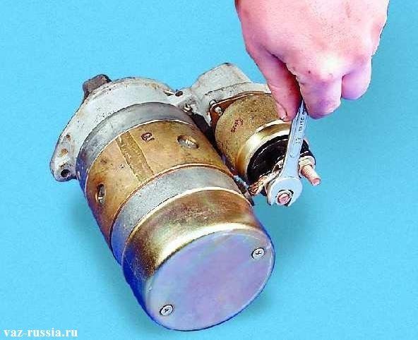
1) At the beginning of the operation, unscrew the nut that is located closer to the starter motor with a wrench, and after unscrewing, remove the starter winding terminal from the pin of the contact bolt, removing the spring and two flat washers.
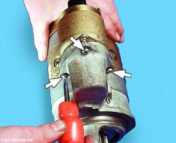
2) Then unscrew the three screws that secure the retractor relay to the cover, and after unscrewing, carefully remove the relay while holding its armature.
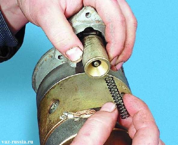
3) After you held the armature thus it did not budge, and the retractor relay was neatly disconnected from it, put the relay aside and grasp the armature thereby remove the spring from it.
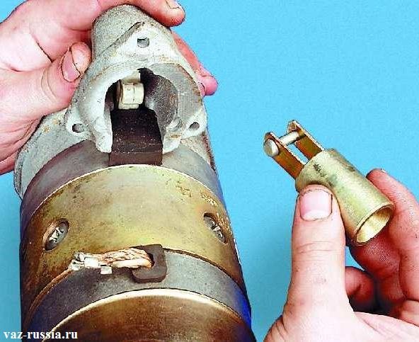
4) Next, grasp the anchor with your hand and pull it straight up, and when it comes out of engagement with the lever that holds it, calmly remove the anchor from the cover and thereby completely remove it.
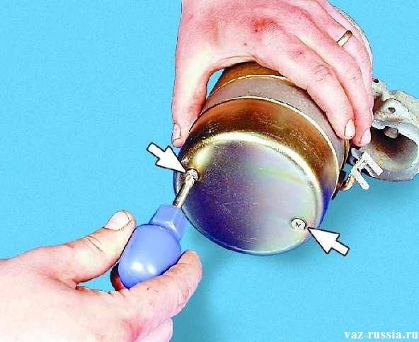
5) Now, when the anchor is removed, use a screwdriver to unscrew the two screws that secure the cover to the electric motor and then detach this cover and set it aside.
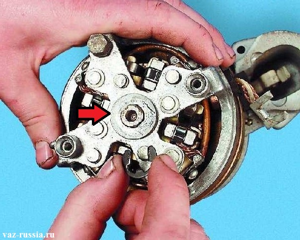
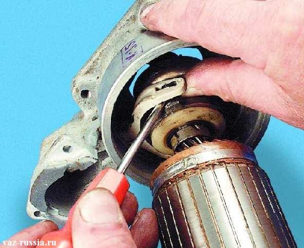
6) After the cover is removed, continue to hold the electric motor and then remove from its central part, first by prying the retaining ring of the shaft with a screwdriver, and then the washer indicated by the arrow.
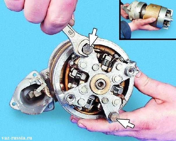
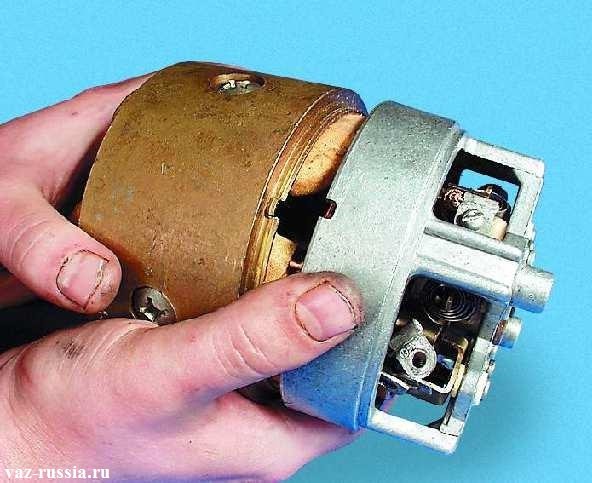
7) Next, unscrew the two tightening bolts with a wrench and then, as shown in the photo in the upper corner, separate the cover together with the main motor, it is also called the rotor, from the body.
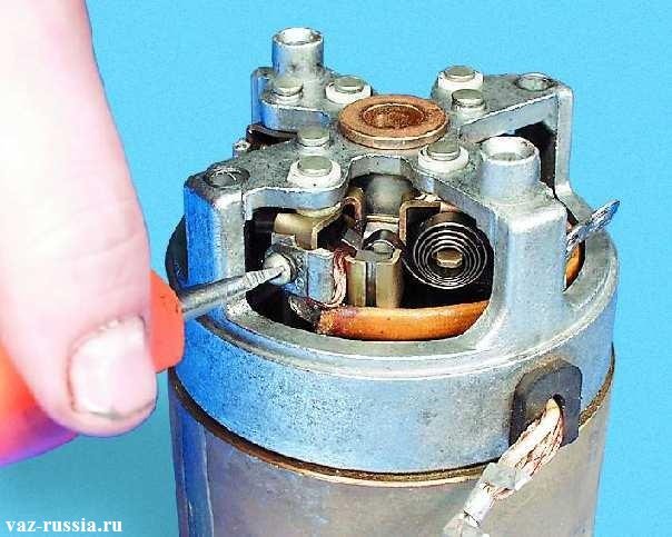
8) Then remove all screws (only one screw is shown in the photo) that hold the stator windings.
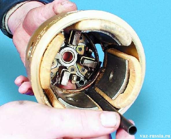
9) Next, look into the inside of the stator and remove the insulating tube from there.
10) Now, when the insulating tube is removed, separate the stator itself and the cover in which several stator elements remain, which will later need to be removed as well.
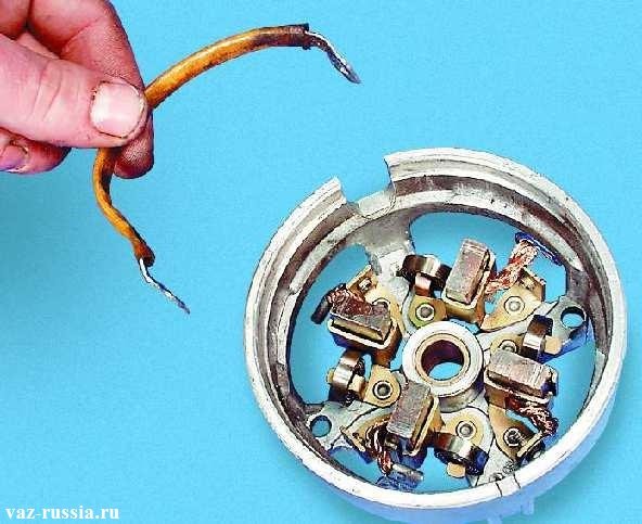
11) Then turn over the cover with the stator elements as shown in the figure, and after turning it over, remove the jumper from the brush holder.
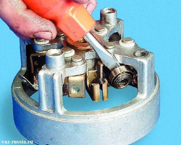
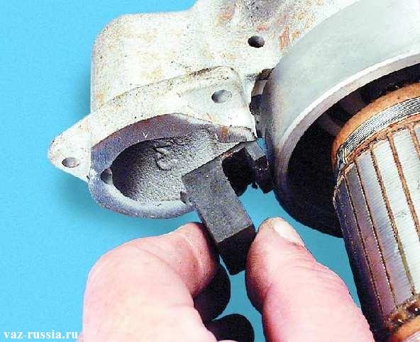
12) Then remove all stator brushes and their springs using a screwdriver.
Note!
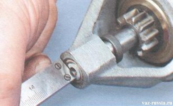
When the brushes are removed, check them with a caliper and if their height is less than 12 mm, then replace these brushes with new ones!
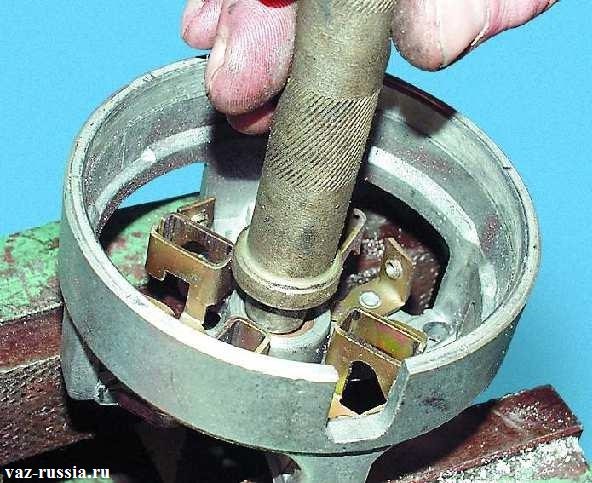
13) Next, take a mandrel of a suitable diameter in your hands and use it to press out the rear bearing, some also call this bearing a bushing.
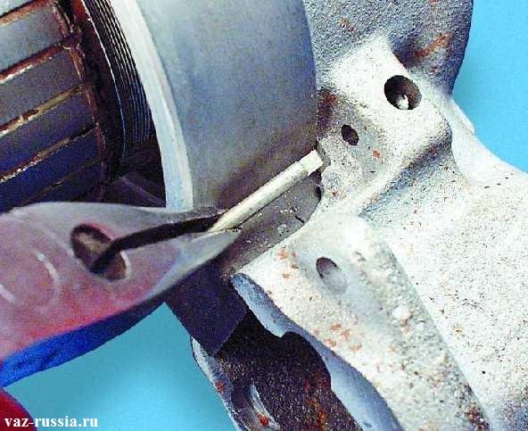
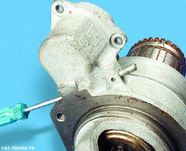
14) Now again take the cover with the rotor in it in your hands and then use the pliers to remove the cotter pin of the axis of the drive lever.
Note!
When the axle pin is removed, remove the drive arm axle itself with a thin screwdriver!
15) Next, remove the rubber plug from the body.
16) And after removing the plug, use a screwdriver to disengage the shoulders with the recesses that are present on the coupling, and when the shoulders are disengaged, remove the anchor itself, or as it is also called the rotor together with the coupling.
17) Then remove the lever at the end of which there are the very shoulders that you previously removed from the engagement with the clutch.
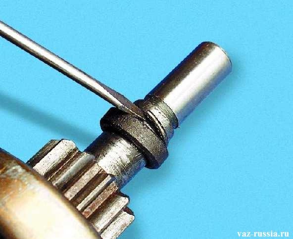
18) Next, using a screwdriver as a lever, move the thrust washer ... (Continued in paragraph 19)
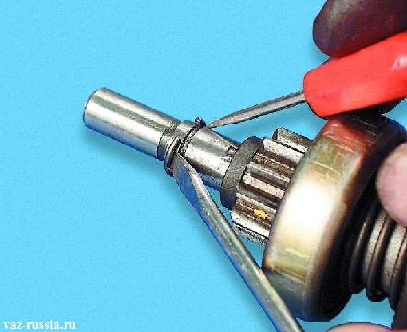
19) And immediately behind it, slide and thereby remove the retaining ring while expanding it with two screwdrivers.
20) Now on the rotor shaft, remove the clutch itself.
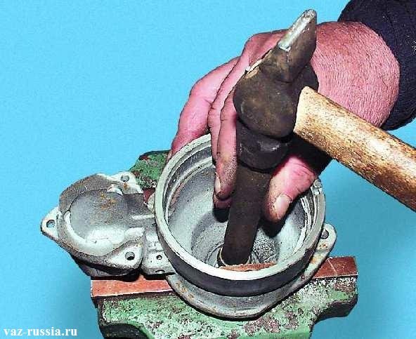
21) Further, when all the details such as an anchor, it is a rotor, etc. To be removed from the housing, lay the housing as shown in the figure and then press the front bearing out of it using a mandrel.
Assembly:
The starter is assembled in the reverse order of removal.
Note!
When reassembling, remember a few features, firstly, if traces of light burning are found on the armature collector, then use a grinding sandpaper to clean the surface of the armature collector from these traces of burning. When everything is cleaned, rinse the collector surface with gasoline or alcohol, and then blow this collector with compressed air so that all small skin and debris is completely removed from the collector surface!
And also when assembling the starter, lubricate the spline part, the shaft journal with engine oil, as well as the gear that is present on the clutch itself and the bushings that are present in the starter caps! (If you do not know where all these parts and all these places are located, then look at the bottom of the heading "Troubleshooting of starter parts", it says everything in detail)
And when the starter is assembled, then using a vernier caliper, check the axial clearance of the armature shaft, to do this, first pull out the shaft completely and write down the resulting value, and then push in this shaft and also write down the resulting value, after comparing these two values, you will get the axial clearance of the armature , which should be no more than 0.5 mm!
Note!
Before starting, I will immediately note the word "Troubleshooting" which was spelled out in the title just above. Not everyone knows what it is and why this is needed for starter parts, we explain. Fault finding - in essence, if you read this word, you can already understand what it is about, that is, the title of this entry is deciphered like this: "Finding defects among the starter parts", this is what we will do now!
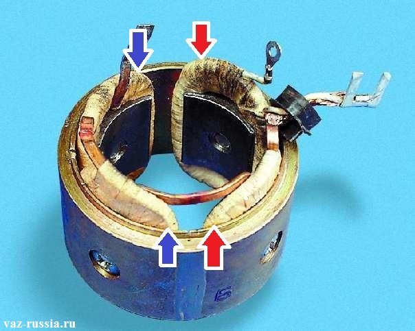
1) After the starter is completely disassembled, the first thing to do is take the stator in your hands and first check the condition of its windings, which should be in good condition and which should not have burn marks. And also check both poles of the stator, which should not have mechanical damage, as well as cracks, etc.
Note!
The poles at the stator, this is essentially the part that is located inside the stator itself, for example, one of the poles in the photo just above is marked with red arrows and the other blue! (But the stator housing itself must also be checked, in which case replace the stator itself with a new one)
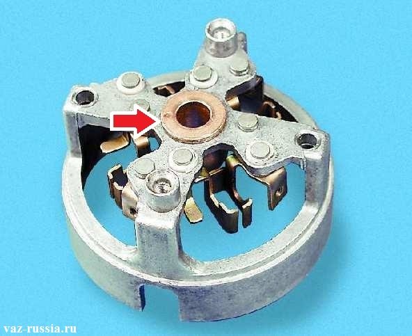
2) Next, inspect one of the covers for cracks, and also take a closer look at the bushing indicated by the arrow, its wear is also not allowed.
3) Now take the anchor itself in your hands and also inspect it for damage, bumps, scoring, pay special attention to the shaft splines (the slots are indicated by the arrow) and also pay attention to the trunnion that is present on the same shaft.
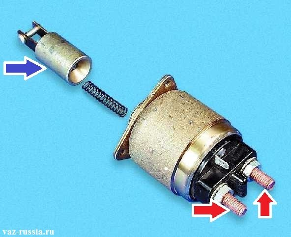
4) Next, check whether the anchor of the solenoid relay (indicated by the blue arrow in a disassembled state) moves easily, and also check with an ohmmeter whether the contact bolts (indicated by the red arrow) are closed by the contact plate. (For what is an ohmmeter, see the article entitled: "What is an ohmmeter")
5) After that, inspect the clutch for defects, the gear teeth of this clutch, which are indicated by the arrow, should not have strong wear.
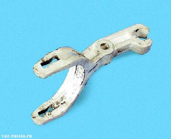
6) And finally, inspect the starter drive lever, on which there should also be no cracks, as well as traces of significant wear of the forks grooves. (Grooves are slots, slots, and joints)
Additional video clip:
If you did not understand something from the written article, then watch the video clip in which the process of replacing the starter bushings is shown, while the starter is almost completely disassembled and everything is clearly very clear, in general, see:
To complete the work, you will need a multimeter and a soldering iron.
1. Remove the starter (see "Starter - removal and installation").
2. We clean the outer surface of the starter from dirt.
3. To check the traction relay, disconnect the starter winding terminal from the contact bolt (see below, “Repair”). We connect terminal “50” of the relay with the positive terminal of the battery, and the starter housing with the negative one. In this case, in a working relay, the armature will push the drive gear into the front cover window, and the contact bolts will close (the resistance tends to zero).
4. To check the stator winding circuits for an open, remove the cover of the rear starter cover and take it out of the brush guides so that they do not touch the housing (see below, “Repair”). Having connected one ohmmeter probe to the body, we alternately connect the other to the brushes and measure the resistance.
In the absence of an open circuit, the ohmmeter should show a winding resistance of about 6 ohms.In the event that the resistance of the windings is greater, they are broken or the connections are oxidized. If the resistance tends to zero, the winding is shorted to ground.
5. For further verification, disassemble the starter (see below, “Repair”).
6. Having connected one ohmmeter probe to the case, we alternately connect the other to the terminals of the stator windings, checking that they are not shorted to the case.
In the absence of a short circuit, the ohmmeter should show a resistance of at least 10 kOhm.
7. Connecting one probe of the ohmmeter to the armature, connect the other alternately to the contact plates, checking the short circuit of the windings to ground.
In the absence of a short circuit, the ohmmeter should show a resistance of at least 10 kOhm.
1. Spanner key by 13 mm we loosen the nut and remove the output of the stator winding from the contact bolt.
2. Key by 8 mm unscrew the three nuts securing the traction relay.
3. Remove the traction relay with a rod and a spring.
4. Key by 8 mm we unscrew the three nuts of the tie rods of the traction relay.
5. To access the power contacts of the solenoid relay, use a soldering iron to heat the soldering of the winding output and disconnect the relay cover.
6. Use a Phillips screwdriver to loosen the rear cover casing tightening screw and remove the casing.
7. Squeezing the springs, remove the four brushes from the guides and set them aside.
8. To facilitate the subsequent assembly, mark the relative position of the case and the back cover.
9. Socket wrench by 10 mm we unscrew the two nuts of the tie rods of the covers.
10. Disconnect the front cover assembly with anchor.
11. Using a Phillips screwdriver, unscrew the screws securing the ends of the stator windings and the terminals of the three brushes.
12. Disconnect the cover from the case.
13. Unscrew the screw securing the output of the fourth brush.
14. Using the pliers, remove the cotter pin holding the lever axis.
15. Push the axle out with a beard.
16. We take out the rubber seal.
17. We remove the anchor. Free-wheel adjusting washers are put on the armature shaft V.
18. Using a screwdriver, squeeze the lever fork and disengage it with the overrunning clutch ring.
19. Remove the lever and shims.
20. Leaning the armature shaft on a wooden block, press the stop ring from the retaining ring with a suitable mandrel.
21. Prying with a slotted screwdriver, remove the retaining ring from the shaft.
22. Remove the stop ring and the overrunning clutch with the drive gear from the armature shaft.
23. Remove the retaining ring with special pliers.
24. Remove the restricting and driving rings, as well as the spring from the freewheel hub.
1. We wash the parts of the starter with white spirit or kerosene, blow through with compressed air. We check the condition of the parts. Covers and body must be free of cracks. Gear teeth should not show significant wear. The gear should turn easily relative to the hub in only one direction - in the direction of rotation of the armature. The surfaces of the splines and journals of the shaft should be free of scoring, nicks and traces of wear. There should be no sticking on the working surface of the collector. Remove minor burns with fine-grained emery paper. The brushes should move freely in the grooves of the brush holders. The brush holders of the "positive" brushes should not be short-circuited to "ground". Replace brushes worn down to a height of less than 12 mm.
2. We visually assess the condition of the traction relay contact group, on which there should be no traces of burnouts. We clean the armature contact plate and contact bolts from carbon deposits and oxides with fine-grained emery paper.
If the burnout depth is more than 2 mm, turn the contact bolts A 180 ° and turn the contact plate B anchors.
3. Lubricate the bearing surfaces and the splines of the armature shaft, the splines of the freewheel hub, the bearing bushings in the starter caps and the axis of the drive lever with engine oil. Lubricate the drive ring of the freewheel hub with grease.
4. Install an overrunning clutch with a drive gear on the armature shaft.
5. We put the stop ring of the gear wheel on the shaft so that the smaller diameter of the inner tapered surface of the ring faces the gear.We install a retaining ring into the groove of the shaft, crimp it and press the stop ring onto it with sliding pliers, if necessary, pushing the retaining ring into the groove with a slotted screwdriver.
6. Next, we assemble the starter in reverse order.
7. Before tightening the nuts of the tie rods, check the axial play of the armature shaft, which should be no more than 0.7 mm. If necessary, adjust it by installing shims on the armature shaft (see above “Repair”, p. 17).
9. Install the traction relay and connect the output of the stator winding to it.
PERFORMANCE ORDER
1. Unscrew the nut on the lower contact bolt of the traction relay and disconnect the stator winding lead from it.
2. Unscrew the nuts securing the traction relay and remove it.
3. At the ST-221 starter, loosen the screw securing the tightening protective tape on the cover 11 (see Fig. Starter parts) from the manifold side and remove the tape 9 with a gasket. Unscrew the screws securing the terminals of the brushes and remove the brushes.
Starter parts
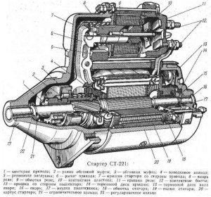
1 - starter cover from the drive side; 2 - rubber plug; 3 - drive lever; 4 - traction relay; 5 - stator pole; 6 - service coil of the stator winding; 7 - shunt coil of the stator winding; 8 - rubber plug; 9 - protective tape; 10 - cover sleeve; 11 - cover from the side of the collector; 12 - brush; 13 - brush spring; 14 - brake disc cover; 15 - case; 16 - tie rod; 17 - anchor; 18 - gear travel stop; 19 - overrunning clutch with drive gear; 20 - restraining ring; 21 - thrust washer; 22 - an adjusting washer
4. At the starter 35.3708, unscrew the screws and remove the protective cover 3 (see Fig. Details of the rear part of the starter 35.3708). Unscrew the screws securing the stator winding leads to the brush holders, remove the springs 2 and brushes 1. Remove the lock washer 4.
Details of the rear part of the starter 35.3708
1 - brush; 2 - brush spring; 3 - protective casing; 4 - lock washer; 5 - adjusting washer; 6 - cover from the collector side
5. At the ST-221 starter (see Fig. Starter parts), unscrew the nuts of the tie rods 16 (on the starter 35.3708, unscrew the tie bolts) and disconnect the body 15 with the cover 11 from the cover 1 with the armature 17. Unscrew the tie rods from the cover 1. Detach the manifold side cover from the housing.
6. Remove the rubber plug 2 of the lever from the drive end cover. Unscrew and remove from the cover the axle of the lever 3 of the starter drive. Remove the lever and armature with the drive from the cover, and then disconnect the arm from the drive.
7. To remove the actuator from the armature, remove the retaining ring from under the retaining ring 20. The actuator is disassembled after removing the retainer washer from the coupling hub.
8. If the traction relay is made in a collapsible design, i.e. the parts of the relay are not sealed in its housing, then to disassemble it, unscrew the nuts of the tie bolts and unsolder the winding leads from the plug "50" and from the tip fixed on the lower contact bolt of the traction relay.
9. After disassembly, blow out the parts with compressed air and wipe clean.
1. Check with a megohmmeter or with a lamp supplied with a voltage of 220 V, whether there is no short circuit of the armature winding to ground.
2. Voltage is supplied through the lamp to the collector plates and to the armature core. Burning of the lamp indicates a short circuit of the collector plates with ground. When checked, the megohmmeter should show a resistance of at least 10 kOhm. Replace the anchor with a short circuit to ground.
3. Use a special device to check if there are any short circuits between the sections of the armature winding and the collector plates, as well as if there are any breaks at the soldering point of the winding sections to the collector plates.
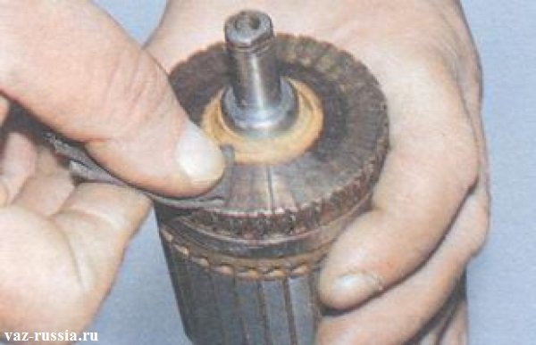
4. Inspect the working surface of the manifold. Clean the dirty or burnt surface with a fine-grained abrasive paper.
5. At the ST-221 starter, check the runout of the collector relative to the shaft journals.
6. If the runout is greater than 0.06 mm, as well as in case of significant damage to the collector surface, grind the collector on a lathe, removing as little metal as possible. The minimum diameter to which the collector can be machined is 36 mm.After grooving, sand the manifold with a fine-grained abrasive paper.
7. Check the runout of the core against the shaft journals. If it is more than 0.08 mm, replace the anchor.
8. Check the condition of the surfaces of the splines and journals of the armature shaft. They should be free of scoring, nicks and wear.
9. If yellow marks from the pinion bushing appear on the surface of the shaft, remove them with a fine-grained abrasive paper, as they may cause the pinion to jam on the shaft.
1. Gear teeth should not show significant wear. If there are nicks on the leading edge of the teeth, grind them with a fine-grained small-diameter emery wheel. The gear should turn easily relative to the clutch hub, but only in the direction of rotation of the armature when starting the engine.
2. If the drive parts are damaged or significantly worn, replace the drive with a new one.
1. Check with a megohmmeter or with a lamp supplied with a voltage of 220 V, whether there is no short circuit of the stator winding to ground. The voltage through the lamp is supplied to the common terminal of the winding and to the starter housing.
2. If the lamp is on or the megohmmeter shows a resistance of less than 10 kOhm, or if the windings have traces of overheating (blackening of the insulation), replace the case with the windings.
1. Check the covers for cracks. If present, replace the covers with new ones.
2. Check the condition of the cover bushings. If they are worn out, replace the cover assembly or only the bushings. After pressing in, unfold new bushings to 12.015 ± 0.03 mm.
3. For the ST-221 starter, to replace the bushing on the manifold side, first remove the plug, and after pressing in the bushing, install the plug in place and open it at three points.
4. Check the reliability of fastening of the brush holders on the cover from the collector side. The brush holders of the positive brushes must not have a short circuit with ground. The brushes should move freely in the grooves of the brush holders. Replace brushes worn in height up to 12 mm with new ones, having previously ground them to the collector.
1. Check the ease of movement of the relay armature. Check with an ohmmeter whether the contact bolts of the relay are closed by the contact plate. Check with an ohmmeter for an open circuit in the traction relay windings.
2. If there is a break in the relay windings or the contact bolts of the relay with a contact plate do not close, then replace the relay with a new one.
3. If the relay is collapsible, then you can disassemble it and clean the contact bolts and the plate with fine-grained sandpaper or a flat velvet file. If the contact bolts are significantly damaged at the point of contact with the contact plate, the bolts can be turned 180 °.
1. Before assembly, lubricate the helical splines of the armature shaft and freewheel hubs, gear and cover bushings with engine oil. Lubricate the drive drive ring with Litol-24 grease.
2. Before starting the assembly, check the axial free movement of the armature shaft by first assembling the covers, body and armature together and tightening the nuts of the tie rods. In this case, the armature can be without a drive, and the front cover without a lever.
3. The axial free travel of the armature shaft at the ST-221 starter should be within 0.07–0.7 mm. Changing the amount of free play is achieved by selecting the number or thickness of adjusting washers 22 (see Fig. Starter parts) located at the front end of the armature shaft.
4. For starter 35.3708, axial free travel of the armature shaft should be no more than 0.5 mm. It is adjusted by selecting the thickness of the adjusting washer 5 (see Fig. Details of the rear part of the starter 35.3708), located between the armature shaft lock washer and the cover on the collector side.
5. Having picked up the adjusting washers, proceed with the assembly, which is performed in the reverse order of disassembly.
6. For the ST-221 starter, put insulating plastic tubes on the tie rods, and for the starter 35.3708, put the insulating plastic tube on the tie bolt passing under the bus of the stator service coils.
7. After assembly, test the starter on the bench.
The article describes in great detail with a photo accompaniment the process of repairing a starter on a VAZ 2110 car.
In a new car, breakdowns and malfunctions in the starter are rare. But if the car has served for more than 5 years, then problems may arise. The car owner himself can determine the malfunction of the starter - the car does not start, uncharacteristic sounds when starting the engine, the starter turns off spontaneously.
But many motorists do not pay attention to such signals from the car. And they bring the situation to the point that it is no longer possible to "save" the starter. But an experienced motorist who monitors his car, immediately, by the sound of a working car, will determine the malfunction of this part. So how do you fix a starter? Its repair takes place in several dozen stages described below.
1. First, you need to remove the starter from the car. Now we proceed to disassemble the part.
3. Disconnect the tire from the traction relay contact bolt.
4. Carefully remove the two bolts that hold the traction relay.
5. The traction relay must be removed from the starter.
6. Set aside the starter itself and remove the armature from the traction relay. To do this, lift it up and the anchor loop is released from the lever.
7. Now we return to the starter itself. Remove the tie rod nuts.
8. The next step is to remove the cover from the drive end with the gearbox and the same assembly part.
9. The cover must also be removed from the side of the collector with brushes and brush holders.
10. Then remove the gear from the anchor shaft.
11. Pull the anchor itself out of the starter.
12. The anchor shaft has a washer on the drive side (pay special attention to this).
13. Use a screwdriver or other thin object to remove the anchor shaft support.
14. Then use a small screwdriver to remove the two tie rods from the starter cover. In general, it is not necessary to remove them, if you are in a hurry, you can leave them, however, it is more convenient to remove the drive and gearbox without these pins.
15. Then remove the three gears of the reducer. A breakdown of the starter may consist precisely in the fact that these gears have damaged, broken teeth or needle bearings embedded in the gears. If this defect is present, then replace the parts and the starter will work again.
16. But, if the gears are in order, then continue to disassemble and check the starter for damage further. It is necessary to remove the gearbox with the drive from the cover, after pressing on the gear of the starter drive.
17. The support with the seal must be removed from the lever.
19. Use a hammer to knock the stop ring off the retaining ring using a suitable arbor.
20. Carefully remove the retaining ring first and then the stop ring.
21. Remove the actuator assembly from the drive shaft.
22. Unscrew the lever retaining ring.
23. Then remove the lever with washer and leash.
24. Use a screwdriver to unscrew the spring of the lever.
25. Now you can remove the lever from the liner, and separate the halves of the lever.
26. Remove the meshing gear retaining ring.
27. Next, disassemble the internal gear and remove the drive shaft support from the shaft.
28. Carefully remove the o-ring from the pore. Examine it carefully. A damaged, deformed, hardened ring will adversely affect the operation of the entire starter. It must be replaced.
29. The next step is to remove the insert from the support.
30. From the side of the collector, unscrew the two screws and remove the brush holder.
31. Using a screwdriver, pry off the brush clips.
32. Then remove these clips and their hold-down springs. Again, replace deformed or damaged parts, heavily compressed or bent, broken springs.
33. Pull the brushes out of the brush holder guides.
34. Uninsulated brushes must be removed.
35. Then remove the cardboard insulation strip. If it is damaged, compressed, torn, replace it with a new one.
36. Remove the insulated brushes with connecting rails.
37. Carefully and in detail inspect the anchor. Pay attention to the collector.
-
1. If the part is dirty, smoked, sand it with glass fine sandpaper. If traces of significant roughness are visible on it or mica protrudes strongly, grind the part on a lathe and then grind the collector with fine sandpaper.
2. If traces of yellow plaque from the bearing are visible on the anchor, then clean it with fine glass sandpaper, because later this can lead to jamming of the shaft gear. If there are dents or nicks on the surfaces of parts such as pins and shaft splines, replace the entire armature. Pay attention to the winding along the ends of the armature. If you see any flaws there, replace the anchor.
38. Using a test lamp supplied with an alternating current of 220 V, check the condition of the armature winding. Connect the lamp voltage to the collector plate and the armature core. If everything is in order, the lamp should not be lit. If, nevertheless, it burns, then the anchor winding has closed. In this case, simply replace the starter armature with a new one.
39. While holding the overrunning clutch, turn the starter gear in both directions: clockwise the gear should move absolutely freely, and should not rotate counterclockwise at all. If something is broken, replace the drive.
40. Then put the starter drive onto the drive shaft. If everything is in order, then it should move freely, without jamming or stopping, along the splines of the shaft.
41. If you see that the drive parts are badly worn, deformed, damaged, replace the drive. If you find nicks on the winding end of the gear teeth, grind them with a fine-grained emery wheel. Choose a circle with a small diameter.
42. Inspect the bushings in which the shafts rotate. They are installed in the starter cover on the drive side, on the manifold side, the armature and drive shaft support. If bushings are deformed or scored, replace covers or supports with broken bushings. Cracked covers and supports should also be replaced.
43. Carefully inspect the starter itself, and if there are traces of anchor rubbing on it, replace the cover and intermediate support with a new one.
44. Worn brushes up to the size between the working surface and the terminal less than 3.5 mm, replace.
45. The brushes must move freely towards the brush holder. And the brush holder should not have cracks, chips, flaws. Check if this is so. If everything is in order, then proceed to the next stage of the repair. If there are faults, replace the parts.
46. Begin inspection of the drive shaft. Its elements should not show signs of damage, severe wear and deformation. If there is plaque, remove it with fine glass sandpaper. Work carefully so as not to damage parts.
47. Using an ohmmeter, check if the contact plate closes the traction relay contact bolts. If they do not close, replace the parts or simply repair the relay.
48. To repair the relay:
- 1. Remove the two screws.
- 2. Unsolder the relay coils and terminals.
- 3. Then remove the cover and sand the pins and bolt heads with a sandpaper. The relay should be assembled in the reverse order.
49. Now proceed with the assembly of the starter. Before starting, lubricate the gear teeth with engine oil. Assemble the starter in reverse order.
50. Install the brush holder into the starter separately from the cover on the collector side. To assemble and install this part, use a bushing with a diameter (mark 1) equal to the diameter of the manifold (approximately 30 millimeters).
51. Install the assembled brush holder into the starter housing until it stops, then remove the bushing and install the cover on the starter from the collector side. The renovation is completed.
And your starter for a VAZ car is as good as new again!
In those cases when your “penny” does not want to start in any way, there is a high probability that its starter is out of order.
Until 1986, a starter was installed on the VAZ 2101 under the marking ST-221. It had a remote control and an overrunning roller clutch. Then it was replaced by the 35.3708 model, which was designed with an end-face collector and a retractor relay with two windings.
ST-221 is a four-pole, grid-type motor operating on a mixed excitation type.
Its structure is quite simple.The main components of ST-221 include: an anchor with a drive; electromagnetic relay; two covers; field windings in a steel casing. The body and covers are connected together by means of pins. Inside this structure, there are four poles that are attached to the body with screws. The winding coils are mounted on the indicated poles. Such a single device forms the stator of the element of interest to us.
In it, two of the four coils are located in parallel with respect to the armature winding, and the other two are connected in series with it. Due to this, the process of excitation of the starter "penny" is called mixed. The design of the 35.3708 model is not much different from the one described above.
It is equipped with a plastic end manifold, which reduces the overall weight of the starter, and also provides a longer and more stable operation of the brush contact. In addition, in model 35.3708, the winding has one shunt and three series coils (the connection with the armature is in series).

