In detail: do-it-yourself repair of the Zil 130 clutch from a real master for the site my.housecope.com.
SPARE PARTS AND ASSEMBLY PARTS
SPECIAL EQUIPMENT BASED ON URAL, MAZ, KAMAZ ____________________
Clutch basket ZIL-130
The pressure plate (basket) of the ZIL-130 clutch is made of gray cast iron SCH 18-36 (GOST 1412-54). If there are cracks on the surface, as well as if the thickness of the disc body is less than 24.7 mm, measured by the mounting boss of the paired spring plates, the clutch pressure plate is rejected.
In case of damage or breakage of the M8 X 1.25 mm thread up to two threads, the clutch pressure plate is installed in a vice, secured and the thread is driven through the four holes with a tap.
A file is used to clean nicks and burrs on the treated surfaces. In case of warping of more than the permissible size, the pressure disk is installed on a ring located on the press table with the plane of contact with the driven disk downwards and straightened. The accuracy of straightening is checked with a ruler and a feeler gauge.
The maximum amount of warpage of the ZIL-130 clutch basket should be no more than 0.15 mm. Seizure marks on the plane of contact with the driven disc are eliminated by grinding.
When the holes for the fingers of the levers are worn, the clutch basket is fixed in a locksmith's vice and the worn holes are expanded to a diameter of 8.4 + 0.058 mm, which corresponds to the first repair size. The repair size holes are marked with paint.
The worn groove of the lever of the ZIL-130 clutch basket is fused to a size of at least 9.0 mm between the ears, and then, fixing the part, the groove is milled in the places of surfacing. The drilled holes in the ears are expanded to a diameter of 8.2 + 0.058 mm.
The control of the performed operation is the checking of the alignment of the hole in the ears with an indicator device. The non-perpendicularity of the axis of the hole to the inner planes of the groove should be no more than 0.3 mm over a length of 100 mm of the pin inserted into the hole.
| Video (click to play). |
The cover of the clutch basket ZIL-130 is made of steel 08 5 mm thick. The part is discarded if there are more than three cracks longer than 50 mm. If there are dents on the surface and adjacent planes, the clutch cover is installed on the die matrix and straightened under a press.
The quality of the operation performed is checked by external inspection and by determining the degree of warpage of the casing, which is checked on the control plate with a feeler gauge. The flatness of the end of the attachment to the flywheel should be no more than 0.5 mm.
If the M8 thread is torn off or worn out, no more than two threads, the cover of the ZIL-130 clutch basket is installed on a stand, the thread is driven in eight holes with a tap, and the nicks and burrs on the surface of the part are cleaned with a file.
If the M8 thread is torn off or worn out, more than two threads, the clutch cover is installed and fixed on the table of the drilling machine and the threaded holes are drilled to a diameter of 12 mm.
Having installed the part on the welding plate, the drilled holes are welded with gas welding. Having cleaned the weld layer flush with the base metal, check the flatness of the end of the casing attachment to the flywheel and, if necessary, adjust the casing using the method described above.
Worn holes for fastening the cover of the ZIL-130 clutch basket to the flywheel, for bushings and nuts, are repaired in a similar way. They are drilled out, welded, the degree of warpage of the casing is checked after welding and, if necessary, corrected.
The final step is to drill holes of nominal size. The holes for fastening the casing to the flywheel are drilled to a diameter of 9.8 mm and reamed.
When the rivets of the plates are loosened, the casing is installed on devices under the press and the rivets are pressed. When the rivets of the plate fastening are torn off or the plates are torn off, defective parts are replaced.
Clutch disc ZIL-130
The ZIL-130 clutch disc is made of 50 steel and phosphated. The hardness of the disc is equal to HRC 35-40. The hub of the driven disc is made of 40X steel, phosphated and passivated in a chromium peak solution. The clutch disc is disassembled at the stand.
When the plates of the friction damper of a larger permissible size are worn, the driven disk is installed and fixed on the table of the drilling machine and with a 0.10 mm drill sharpened at an angle of 90 °, the heads of the rivets are cut to the level of the base metal, rivets are knocked out, the worn-out plates of the damper are removed, and then new ones are installed plates and re-riveted.
Before riveting the friction linings, the ZIL-130 clutch disc is adjusted, after having cleaned the nicks and burrs on the hub. The control of the performed operation is to check the degree of warpage of the disc on the plate using a feeler gauge.
The clutch disc friction linings are riveted under pressure using a die. After riveting the friction linings, check the degree of warpage of the disc and the amount of runout with an indicator device.
The warpage should not exceed 0.3 mm, and the runout should not exceed 0.8 mm. If necessary, the driven ZIL-130 clutch disc is driven along the spokes on the plate and the imbalance relative to the lateral surface of the slot is checked.
The permissible imbalance should not exceed 25 Gsm. An imbalance of more than 25 Gsm is eliminated by installing weights, which are fixedly fixed by bending the tendrils of the driven clutch disc. When a bending moment of 45 kgm is applied to the hub, the rotation angle of the hub should not exceed 1 ° 30'-2 °.
The frictional moment of the damper should be within the range of 1-4 kgm. The damper is checked by turning the hub relative to the fixed disk in a device that excludes radial load.
Clutch housing ZIL-130
The clutch housing ZIL-130 is made of gray cast iron Сч 15-32. If there are cracks with a length of more than 150 mm passing through the hole for the bearing of the drive shaft and stiffeners, as well as the hole for attaching the clutch housing to the cylinder block, the clutch housing is rejected.
The engine clutch crankcase is not interchangeable with the cylinder block, since during their manufacture the centering surfaces are finally machined together with the cylinder block.
Disassembly of this unit is necessary for the following reasons: the cylinder block and the ZIL-130 clutch housing have different repair complexity factors; these parts are uneven; the crankcase and the block of cylinders must be flushed and defective separately.
To prevent disassembly of the unit and to ensure the alignment of the engine crankshaft and the transmission drive shaft in a small production program, these units are marked.
When the bolt is broken in the threaded hole, the ZIL-130 clutch housing is installed on a locksmith's workbench, the center of the broken bolt is screwed on and a blind hole is drilled to a depth of 8-10 mm with a drill. Then a square mandrel is driven into the drilled hole of the bolt and the broken part of the bolt is unscrewed from the threaded hole of the clutch housing.
The final operation is threading and deburring and deburring on all machined planes. Worn out more than the permissible size of the bushings of the clutch fork shaft are pressed out using a mandrel, after having installed the clutch housing on a stand fixed on the press table.
After pressing out the worn bushings, check the wear of the hole for the bushings of the clutch fork shaft. Holes having a diameter greater than 30.05 mm are expanded in a line up to 30.2 + 0.045 mm.
Using a mandrel under a press, bushings of nominal or repair size are pressed into the hole, depending on the diameter of the hole, having previously aligned the hole in the bushing with the hole in the ZIL-130 clutch housing. The pressed-in sleeves are expanded in a line to a diameter of 25 + 0.06 mm.
After assembling the clutch housing with the cylinder block, the centering hole of the clutch housing is bored into the tool.The worn hole is bored to a diameter of 166 + 0.04 mm through the passage and the groove under the collar is ground to a depth of 2.5 ± 0.1 mm.
A sleeve is pressed into the bored hole using a mandrel until it stops. The pressed-in liner is finally bored together with the engine block to ensure the alignment of the axes of the engine crankshaft and the transmission drive shaft.
ZIL-130 clutch basket lever and lever fork
The lever of the pressure plate (basket) of the ZIL-130 clutch is made of steel 35 GOST 1050-60 and cyanide to a depth of 0.15-0.3 mm. Lever hardness - HRC 56-62. The lever is rejected in the presence of cracks and breaks with a length of more than 5 mm on the surface.
The geometrical parameters of the processed spherical surface of the lever are determined using a template for transmission. When the hole for needle bearings is worn over the allowable size, the clutch basket lever is ground.
The pressure plate levers, which have holes for oversized needle bearings, are marked with paint in order to assemble them with enlarged pins during assembly.
The lever fork of the ZIL-130 clutch basket is made of steel 45. The fork is rejected if there are cracks of any nature and location, as well as if the fork attachment ears are broken.
In the presence of nicks and burrs, the fork of the clutch release lever is clamped in a vice with soft jaws and the processed surfaces are cleaned with a file. A thread torn off or worn out to two threads is driven through with a tap.
When the holes for the finger in the lugs are worn out, the fork is fixed in a vice with soft jaws and two holes are deployed in a line to a diameter of 8.4 + 0.058 mm, which corresponds to the first repair dimension.
Forks with oversized holes are marked with paint to pick up a finger during assembly
increased diameter.
Assembling the clutch ZIL-130
Before assembling, it is necessary to complete the parts of the ZIL-130 clutch according to the size of the holes in the fork and the pressure plate for the finger and fingers in diameter. To assemble the clutch, a pressure plate is installed on the stand.
Needles 19 (Fig. 4) of the needle bearing, pre-lubricated with oil, are inserted into the holes of the clutch release lever together with a technological ball with a diameter of 8.8 - 9.5 mm, made of soft oil-resistant rubber. Similarly, insert the needle bearing needles into the second hole in the lever.
Then, the hole of the support fork 17 is aligned with the hole of the lever 18, while guiding the spherical protrusion of the inner end of the lever 18 in one direction with the threaded end of the fork. When stub pin 16 is inserted into the aligned holes, the rubber process ball is pushed out. The inserted finger is pinned.
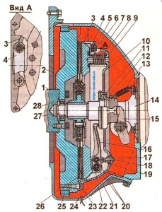
Rice. 4. Assembly parts of the ZIL-130 clutch
1 - pressure disk (basket); 2 - driven disk; 3 - friction linings; 4 - spring of the elastic coupling of the damper; 5 — base plate of the spring; 6 — steel plate of a friction damper; 7 - friction damper disk; 8 - oil deflector; 9 — hub; 10 - heat insulating washers; 11 - pressure spring; 12 — pressure plate bolt; 13 — pressure plate; 14 — adjusting nut; 15 - clutch cover; 16 and 20 - fingers of the fork and lever; 17 - support fork; 18 - clutch release lever; 19 - needles of the needle bearing; 20 - finger
In the absence of rubber balls, the roller bearing needles are assembled with a layer of grease on the surface of the holes. The rollers are laid in the second hole after assembling the lever with the fork. To install the lever 18 (Fig. 4) for disengaging the clutch in the groove of the pressure plate bracket, the holes in the lever and the bracket are aligned.
Having inserted the long pin 20 into the aligned holes, the technological rubber ball is pushed out and pin 20 is pinned. The rest of the levers are set in the same way.
Then, heat-insulating washers 10 and pressure springs 11 are installed on the protrusions of the ZIL-130 clutch basket. The clutch cover 15 is applied to the springs 11, directing the threaded ends of the support forks 17 into the holes of the cover 15.
Technological caps are put on the threaded ends of the support forks to prevent damage to the threads during subsequent assembly operations. Technological guide mandrels are inserted into the flange holes of the clutch casing and the springs 11 are compressed by pressing on the clutch casing 15.
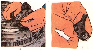
Taking out the technological guide mandrels and removing the technological caps from the threaded ends of the forks 17, install the bushings into the shaped holes of the paired spring plates, screw in the bolts of these plates, which are tightened with a torque wrench with a torque of 1.0-1.5 kgm. After tightening, all bolts are locked by bending the thin shoulder of the bushing to the edge of the bolt head.
The adjusting nuts 14 are screwed onto the threaded ends of the forks 17 with an adjusting key until the end of the nut coincides with the end of the threaded end of the fork 17.
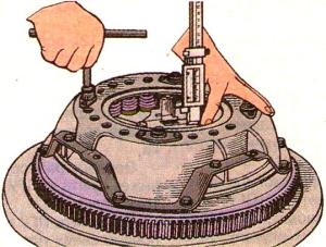
Clamping plates 13 are installed on the forks with adjusting nuts, clamping bolts 12 are screwed in by hand, which are tightened with a socket wrench until the plates 13 stop in the casing 15. The position of the levers relative to the ZIL-130 clutch basket is adjusted using an indicator device.
Turning the adjusting nuts with a wrench, set all the levers in such a position that, with a size of 9.7-9.9 mm between the end of the casing and the end of the plane of the pressure plate, set the size of 39.7-40.7 mm between the end of the basket and the support heel of the levers.
The ends of the levers must lie in the same plane parallel to the working surface of the pressure plate with an accuracy of 0.5 mm.
After adjusting the ZIL-130 clutch, the mounting bolts of the base plates are tightened with a torque wrench and pinned with a soft steel wire with a diameter of 1.0 mm.
To prevent spontaneous loosening, the threaded connection of the adjusting nut is screwed onto the threaded end of the fork.
The final operation is static balancing of the pressure plate assembly with the casing on the balancing device. With an unbalance value of more than 50 Gsm, holes are drilled in the bosses to a depth of no more than 23 mm with a Ø 13.7 mm drill. The mounting holes are marked.
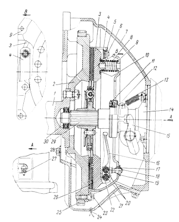
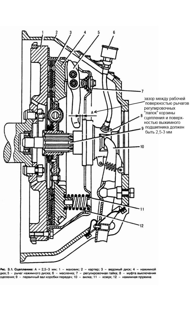
Clutch (Fig. 35) single-disk dry, installed in a cast iron crankcase 7. The clutch cover 9 is fixed to the flywheel 2 of the crankshaft 1 by eight centering (special) bolts 23. The clutch pressure is generated by sixteen springs installed between the clutch cover 9 and the pressure plate 3. Heat insulating rings are placed under the springs on the side of the pressure plate.
The transmission of torque from the clutch cover 9 to the driven disc is carried out through the pressure plate 3 by four pairs of spring plates 4.
The switching device consists of four levers 16, which are connected by fingers 20 with a pressure plate and a fork 18. Needle rollers 22 are placed between the fingers 20 and the lever 16.
The position of the clutch release levers 16 is adjusted by the nuts 17, which, after adjustment, are pitted.
During operation of the vehicle, the position of these levers is not adjusted.
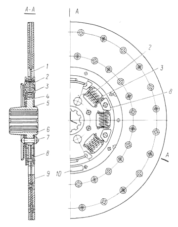
The clutch disc (Fig. 36) is steel, with friction linings, has a torsional vibration damper (damper) of a frictional type (with dry friction of steel on steel). Eight springs evenly spaced around the circumference are the elastic coupling of the damper 2.
The driven disc is balanced. Balancing is carried out by installing balancing plates 10 on the driven disk.
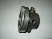
To disengage the clutch, a thrust bearing 11 (Fig. 35), mounted on the bearing sleeve 12, is used. The bearing 11 is lubricated at the factory and is not added during operation and repair. During the repair of the clutch, the bearing should be replaced with a new one if necessary.
With a correctly adjusted clutch drive, the gap between the lever 16 and the clutch release bearing should be 3-4 mm.
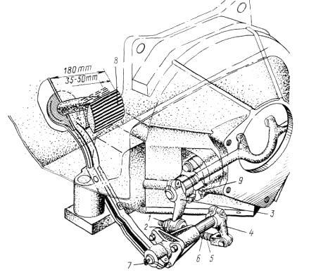
To disengage the clutch, a foot pedal is used, which is installed on a bracket attached to the left side member of the car frame. The lower end of the pedal is connected by an adjustable rod 5 (Fig. 37) with the lever 3 of the clutch release fork.The pedal travel is limited by an emphasis on the cab floor.
A correctly adjusted clutch should not slip in the disengaged position, and when the pedal is depressed, it should disengage completely (should not "lead"). The free travel of the clutch pedal must be 35-50 mm, and the total travel must be at least 180 mm.
As the friction linings wear down, the clutch pedal free play decreases, and as a result, the clutch can slip. This leads to rapid wear of the driven disc and the clutch bearing. In case of excessive free travel (over 50 mm), pressing the pedal to failure does not completely disengage the clutch. In this case, there is a rapid wear of the driven disk and gear shifting becomes difficult.
Pedal free travel must be adjusted in the following order:
1. Adjust the lock nut 1.
2. Adjust the free travel of the clutch pedal by turning the spherical adjusting nut 2; to reduce the free play of the pedal, the spherical nut should be screwed onto the rod 5, and to increase the free play, it must be rolled off the rod.
4. After adjusting, start the engine and check for proper clutch operation.
Maintenance consists in adjusting the clutch drive, cleaning from dirt, timely tightening of all bolt connections, lubricating the clutch release fork and pedal shaft in accordance with the lubrication table.
The front bearing 30 (Fig. 35) of the gearbox drive shaft has a constant supply of grease supplied at the bearing manufacturer. Periodic replenishment of grease is not required during operation. During repair work, the bearing must be replaced with a new one if necessary.
It is necessary to carefully monitor the tightening of the bolts securing the clutch housing to the cylinder block. The tightening torque of the bolts should be equal to 8-10 kgf-m (80-100 Nm). The bolts must be tightened evenly, consistently, crosswise.
Illustrations for the section
Rice. 35. Clutch
1 - crankshaft; 2 - flywheel; 3 - pressure plate; 4 - spring plate; 5 - bushing of spring plates; 6 - bolt for fastening the plates; 7 - clutch housing; 8 - pressure spring; 9 - casing; 10 - heat insulating washer of the pressure spring; 11 - thrust bearing; 12- clutch; 13 - clutch release spring; 14 - guide clutch; 15 - clutch release fork; 16-clutch release lever; 17 - fork adjusting nut; 18 - plug; 19- base plate of the adjusting nut; 20- fingers; 21 - crankcase cover; 22 - rollers; 23 - bolt of fastening of the clutch cover to the flywheel, 24 - cotter pin; 25 - flywheel crown; 26 - driven disk; 27 - oiler for lubricating the clutch release fork; 28 - shield; 29 - transmission drive shaft; 30 - front bearing of the drive shaft of the gearbox
Rice. 36. Driven clutch disc
1 - driven disk; 2 -spring of the torsional vibration damper (damper); 3 - base plate; 4 - oil deflector; 5 - damper disk; 6 - the hub of the driven disk; 7 - rivet; 8 - friction pad of the damper; 9 - friction lining of the driven disk; 10 - balancing plate
Rice. 37. Clutch drive
1-lock nut - 2 - spherical nut; 3 - clutch release fork lever; 4 - intermediate lever; 5 - thrust; 6 - pedal shaft; 7 - grease fittings for pedal shaft bushings
8 - pedal; 9 - oiler for lubricating the bushings of the clutch release fork
Before considering specifically the Zil 130 clutch, I would like to say a few words about the car itself. Zil 130 is a legendary Soviet truck, simple and unpretentious. The first series of cars was produced back in 1962, but even today you can find these serviceable workers on the streets of cities and villages. They are not afraid of bad roads and low-quality fuel. In addition, on the highway, they can reach speeds of up to 100 kilometers per hour. Of the shortcomings of the model, it is perhaps worth noting the high fuel consumption, which can reach 30 liters per hundred kilometers.
With proper care and timely maintenance, the ZIL 130 can operate without problems for decades. There are living examples of this. However, it is advisable for any owner of this truck to be well versed in its device in order to be able to carry out some of the necessary operations on their own. For example, you need to know how to adjust the Zil 130 clutch. First, let's look at how it works.
The Zil 130 truck clutch can be described as:
It is housed in a cast iron crankcase that is attached to the motor. Its cover is attached to the crankshaft flywheel with eight centering bolts. The pressing force is created by sixteen springs that are installed between the clutch housing and its pressure plate. Special heat-insulating washers lie under them. They are able to reduce the heating of the springs. Thanks to these washers, the springs do not lose their elastic properties due to heating. Torque is transmitted from the casing to the driven disc by means of a pressure plate and four pairs of spring plates. The clutch release device consists of four levers that are connected to the fork and pressure plate by fingers. Needle rollers are located between these pins and each arm. Spherical nuts are used to support the forks. They enable the forks to oscillate as the pressure plate moves.
In the clutch release there is a release bearing, which is non-separable. Therefore, during operation, the amount of oil in this bearing cannot be replenished. The clutch disc is made of steel and has friction linings made of pressed metal-asbestos composition. To disengage the clutch, a pedal with a shaft installed in the bracket is used. The travel of this pedal limits the floor in the truck cab.
In order for the clutch to always work reliably, it needs periodic adjustment. From time to time, owners of trucks ZIL 130 have to adjust the free travel of the clutch pedal, as well as the position of the release levers. The pedal free play is adjusted with the adjusting nut. The gap between the release bearing and the clutch release levers must be from one and a half to three millimeters. In this case, the free travel of the clutch pedal will be between thirty-five and fifty millimeters. This adjustment provides full engagement and disengagement of the clutch of the ZIL 130 truck. If the gap between the release bearing and the release levers is less than one and a half millimeters, then the release bearing will occasionally touch the release levers. This will be accompanied by slipping of the clutch and, as a result, increased wear of the bearing itself, as well as the release levers and friction linings.
Truck clutch release levers are adjusted during clutch assembly or repair using special ball nuts. Such an adjustment is required for the possibility of smooth, without skewing, movement of the pressure plate when the clutch is disengaged. If you neglect it, then the pressure plate will move away from the driven disk unevenly. As a result, increased wear of the entire unit will occur, which will lead to its premature failure.
The clutch of the Zil 130 truck may not be completely disengaged due to skew or warpage of the driven disc, as well as if there is an uneven gap between the discs. Most often, such a nuisance occurs due to overheating as a result of prolonged slip. This problem can be solved simply by replacing the warped discs. If the friction linings fail, they can create a wedge between the drive and driven discs. As a result, the clutch will not fully disengage. If this happens, you should disassemble the unit and change the friction linings. When the clutch is disengaged, and the pressure plate still continues to touch the driven plate slightly, adjustment of the position of the release levers is necessary.
If the car starts to move with some jerk, then, most likely, this malfunction is associated with a stuck release clutch located on the input shaft bearing cover. This is due to the fact that when the driver releases the clutch pedal, the clutch moves unevenly, at first seizing and then jerking sharply. In addition, warped discs can cause the clutch to engage abruptly. In this case, to eliminate the malfunction, they will need to be replaced.
In order for the Zil 130 truck to need repairs as rarely as possible, it is necessary to operate it in compliance with several simple rules. You can get under way in both first and second gear. Try to release the clutch pedal as smoothly as possible. Do not keep your foot on the pedal when parked with the engine running. In addition, the pedal must not be partially depressed while driving. This leads to premature wear and early failure of the entire assembly. Do not drive and shift gears at high engine speeds. The above adjustments must be carried out periodically. Compliance with these simple rules will help keep the unit operational for as long as possible, as well as exclude unforeseen breakdowns.
ZIL-130 clutch elements:
-
pressure plate (clutch basket)
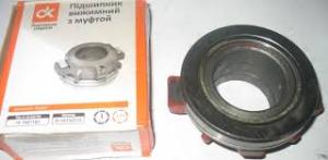
clutch release bearing
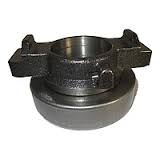
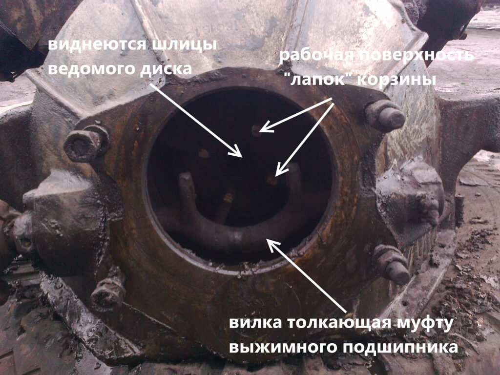
The clutch can be adjusted on the dismantled pressure plate (for example, after replacing the clutch disc, or replacing the pressure plate pads or release bearing) or directly on the car through an open flap in the flywheel. Consider the option of dismantling the gearbox and all clutch parts.
Dismantling is carried out on a viewing ditch using a special winch to remove the gearbox:
- Having unscrewed 4 (four) fastening nuts - the gearbox is removed and lowered onto the pallet.
- Now unscrew the 8 (eight) bolts securing the pressure plate to the engine flywheel.
- Gently, holding the driven disc (which is sandwiched between the flywheel and the basket), remove the pressure disc.
- Troubleshooting of all clutch parts is being carried out.
- The release bearing is checked - it should rotate easily without emitting extraneous sounds.
- Look at the working surface of the pressure plate paws. Determine the thickness of the friction linings of the driven disc.
When all the parts are sorted out and replaced with new ones, it is necessary to adjust the four levers of the pressure plate or, as they are simply called, the clutch basket “legs”. This will require a flat plate, which is used as a spare flywheel of the ZIL-130 engine. If there is none, you need to purchase it for disassembly.
Without removing the assembled clutch pressure plate (basket) from the auxiliary flywheel (used as a device), it is necessary to adjust the position of the levers relative to the working surface of the pressure plate.
Turning the adjusting nuts with a wrench, set all levers in such a position that the distance from the working surface of the pressure plate to the tops of the spherical protrusions on the inner ends of the levers is within 39.7-40.7 mm. In this case, the ends of the levers must lie in the same plane parallel to the working surface of the pressure plate with an accuracy of 0.5 mm, no more.
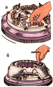
In the event that the clutch pressure plate is assembled in the adjusting device, the installation of the levers should be checked using a control plate, as shown in fig. 1, b. In this case, the spherical protrusions of the levers must touch the control plate 2 installed on the hub of the tool 1.
After finishing the clutch adjustment, it is necessary to tighten the bolts of the support plates (tightening torque 1.0-1.5 kgm). Then, pin the bolts (figure eight) with a soft annealed steel wire 1 mm in diameter.
Tighten the threaded connection of the adjusting nut with the threaded end of the fork at one point.
Remove the cover bolts to the auxiliary flywheel and remove the pressure plate assembly with the cover.In this case, loosen all the bolts gradually and sequentially in order to avoid deformation of the clutch cover.
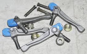
This is how the adjusting lever looks like, or on a simple foot of the ZIL 130 pressure disk:
Assembling the pressure plate (basket)
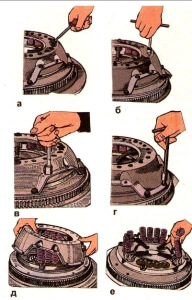
It is possible to adjust the pull-off levers without removing the clutch basket from the flywheel of the car.
When removing the clutch, it is necessary to unscrew the bolts securing the gearbox to the clutch housing, disconnect the gearbox from the crankcase and remove it;
- unscrew the bolts of the clutch cover and remove it;
- unscrew the bolts securing the lower clutch housing cover and remove the cover;
- loosen the clamping bolt securing the lever on the fork shaft, remove the lever and remove the key;
- loosen the two bolts of the bushing flange and remove it;
- remove the clutch release fork by first sliding it to the left and tilting it down.
The clutch / crankshaft assembly is dynamically balanced at the factory. To maintain balance, markings must be made on the flywheel and pressure plate cover before removing the clutch from the flywheel. This will allow them to be installed in the same position during assembly without disturbing the factory balance.
Remove the bolts securing the pressure plate cover to the flywheel. Unscrewing the bytes, it is necessary to sequentially turn the flywheel. The screws should be loosened gradually to avoid deformation of the casing.
Remove the pressure plate assembly, remove the clutch disc.
Disassembly of the pressure plate. Before starting disassembly, it is necessary to mark the relative position of all clutch parts. To disassemble the pressure plate, use the auxiliary flywheel and 9.8 mm steel plate. replacement driven disc. Any rigid spacer of the specified size can also be used in place of the steel disc. If necessary, various devices with quick-acting clamps can be used to disassemble the pressure plate, but with the obligatory installation of the pressure plate casing on eight centering pins or bolts, followed by pressing the casing by its paws.
To disassemble the clutch pressure plate, you need to install the flywheel on a workbench, put a steel disk on the working surface of the flywheel, install the pressure plate assembly with a casing on it and fix it on the flywheel with centering elongated bolts. The bolts should be 10-12 mm longer than the normal cowl bolts.
It is recommended to disassemble the pressure plate in the following order. Undo the cotter bolts of the support plates, unscrew them and remove the plates from the clutch cover. Unscrew the adjusting nuts with a special wrench.
Unscrew the bolts securing the paired spring plates and remove the guide bushings from the shaped holes of these plates. Then gradually unscrew all the bolts securing the casing to the flywheel until the pressure springs are completely released from compression, and then completely unscrew all these bolts. Remove cover, pressure springs and heat insulating washers.
Mark the position of each clutch release lever relative to the pressure plate, uncouple and remove the pins connecting the levers with the pressure plate, remove the levers complete with support forks, remove the rollers from the levers sockets. Unpin and remove the pins connecting the levers with the support forks, remove the forks from the levers and remove the rollers from the levers sockets. Remove the pressure plate from the auxiliary flywheel.
In the absence of additional extended bolts, the pressure plate can be disassembled in the following way.
Install the pressure plate assembly onto the flywheel with 9.8 mm steel sub-disc. and secure with normal bolts.
Undo the cotter pins and unscrew the bolts securing the base plates, remove the plates from the casing. Unscrew the bolts securing the paired spring plates and remove the guide bushings from the shaped holes in the plates.Unscrew the pre-adjusting nuts and leave them on the forks (about half the height of the threaded part of the nut); then unscrew all the normal bolts securing the clutch cover on the flywheel, then, pressing the casing by hand, unscrew the adjusting nuts finally, rolling them in pairs from opposite sides of the casing until the springs are completely released from compression. Then remove: the clutch cover, pressure springs, heat-insulating washers, clutch release levers and pressure plate from the flywheel.
Having disassembled the clutch, it is necessary to rinse the parts in a degreasing solution, check their suitability, and, if necessary, replace the unusable parts with new ones.
In this article, we will consider what are the main details clutch ZIL 130 and how the basket legs can be adjusted.
What motorists and craftsmen call each other "Basket" has an official technical name - drive pressure disk... It is designed to transfer torque from the engine flywheel to clutch disc... For the operation of the pressure plate, the basket is equipped with a cast iron casing, by means of which the entire mechanism is bolted to the flywheel.
Sixteen springs are located under the casing. Through their efforts, pressure is exerted. In order to disengage the clutch, the pressure plate has four pull-off levers (in the jargon "paws").
Steel disc with friction lining on both sides (in the jargon "feredo" from the word ferodo, which means friction heat-resistant composite material). The pads are attached with rivets. If you have a device and replaceable feredos, they can be replaced to restore the disk's performance. The photo below shows the thickness of the friction linings on the new disk.
During operation, due to friction and thermal overload, the disc is erased and becomes unusable. The damper part is also damaged (springs fly off) and the guide splines wear out, and the steel base of the disc also cracks.
A damper and a slotted hole are located in the central part of the disk, which fit into the splines of the gearbox input shaft. The damper section with eight springs serves as a damper.
Release bearing fixed on the coupling, which has stops on both sides. These stops allow the coupling with the bearing to be moved using clutch release forks... By depressing the clutch pedal, you move this fork. She, in turn, moves the "release" towards the "basket", where the bearing rests against the release levers. The levers push the drive disc away from the follower and the clutch is disengaged as long as you keep the clutch pedal depressed. You can find a detailed diagram of the clutch drive as well as a guide for adjusting the clutch pedal free travel in our article - Free travel of the clutch pedal zil 130. Adjustment.
Thus, the ZIL 130 clutch is arranged in the simplest way, without pneumatic hydraulic boosters and using one driven disc. (For example, on KamAZ, MAZ and KrAZ, two driven discs are used between which an intermediate plate is installed, and the release force is increased with the help of the CCGT).
Dismantling is most conveniently done on a viewing ditch using a special winch for removing the gearbox. Dismantling procedure:
- Remove the four nuts securing the gearbox to the engine cover.
- Moving away from the engine, pull the gearbox off the mounting studs and lower it onto the pallet with a winch. There will be a release bearing on the input shaft of the gearbox.
- Remove the eight pressure plate-to-flywheel bolts.
- Gently, holding the driven disc (which is sandwiched between the flywheel and the basket), remove the pressure disc.
After that, you can inspect the condition of the parts: the working surface of the pressure plate paws, evaluate the wear of the friction linings of the driven disk. The working release bearing must rotate easily without emitting extraneous sounds.
The basket legs are adjusted after repair or replacement of the clutch elements discussed above.Reliable and long-term clutch performance depends on correctly positioned levers. The main task is to achieve finding the working surface of the levers at a certain distance from the pressure plate and always in the same plane in order to avoid skewing.
For adjustment, an auxiliary flywheel is required, which can be purchased at disassembly.
Without removing the assembled clutch pressure plate (basket) from the auxiliary flywheel (used as a device), it is necessary to adjust the position of the levers relative to the working surface of the pressure plate.
Turning the adjusting nuts with a wrench, set all levers in such a position that distance from the working surface of the pressure plate to the tops of the spherical protrusions on the inner ends of the levers was within 39.7-40.7 mm... In this case, the ends of the levers must lie in the same plane parallel to the working surface of the pressure plate with an accuracy of 0.5 mm, no more.
After finishing the clutch adjustment, it is necessary to tighten the bolts of the support plates (tightening torque 1.0-1.5 kgm). Then, pin the bolts (figure eight) with a soft annealed steel wire 1 mm in diameter.
| Video (click to play). |
Tighten the threaded connection of the adjusting nut with the threaded end of the fork at one point.
Remove the cover bolts to the auxiliary flywheel and remove the pressure plate assembly with the cover. In this case, loosen all the bolts gradually and sequentially in order to avoid deformation of the clutch cover.

