In detail: do-it-yourself repair of a MMA 250 welding inverter from a real master for the site my.housecope.com.
Compound:
master oscillator - uc3846dw, tl082 and 2 pcs. tl084i, buildup - ao4606, keys - gw45hf60wd, output rectifier - stth60w03cw
They brought it without any signs of life. The check revealed a dead roll at 12 V (exploded) and 4N90C. I changed it, I turn it on. Power supply +24, +12 and -15, everything is stable, there is a saw on the master, the output is silent. I further check the elements for deadness - the diodes are alive, I have not checked the keys yet, there are two small scarves in the key chains on which in the middle there are 2 either a dinistor or a zener diode. in general, I did not find data in the tyrnete. Marking BM1238 and BM1243. Maybe someone can tell me? In the board, one side does not ring at all, the other - as if a capacitor is charged, and then infinity. It should be?
It would not hurt to have a diagram from him, but I can't find something. Found a couple of similar ones, but a little not that. If there is, please share. A device with a vertical arrangement of connectors.
is there a processor? I did not indicate it in the composition, but I cannot understand from the pictures
Check the keys. I personally solder each transistor and check it. It's hard to find a defect there.
Radist morze, BMxxxx? These are bidirectional zener diodes in IGBT gates at 15v, you can set both 15v and 18v. Download information on SMAJxxxxx and make sure. Yes, in principle, any circuit with such a set of circuits as in Gerrard Edon mma-250 is confirmation of this. the numbering will be different.
REKKA, but where does the processor come from? This is not a 20-30 mowing machine.
Irina Slava, thanks for the comprehensive answer. I watched some kind of circuit, and I also came to the conclusion that these are zener diodes, only in that circuit they are inversely connected in series. And I already know about numbering. It's just that the composition is slightly different. Apparently, here is 3846 with external excitation, and this generator is on tl082. After it there are 2 pieces of tl084i, and then 3846. And in that diagram, everything is on tl084.
found a broken diode. one of the counter-parallel included in the tl082 strapping. Now I will look for Old and Replacement.
| Video (click to play). |
the diode was in a semi-torn state, if you press it down with a probe, it rings. on the board at first it also called, then stopped. I changed it, but it's no use.
Radist morze, the network has a MMA ZX7-225 scheme, here it is. close to required or ZX7200IGBT.
this scheme is suitable for my Dnieper, it is also three-story. and this is a stranger. " e-don ”single board. Well I write above that with a vertical arrangement of bayonet connectors.
REKKA, what have the keys to do with it when the control impulses do not come from the micro? on 3846 there is a saw on leg 8, there is an impulse on leg 10, and the exit is dead.
by the way, I thought that 3846 was dead, replaced - the same thing. tl082 also replaced, there is no sense either. I sin on tl084i, but I don't have them
here the ZX-7 diagram is similar, but not completely identical in details.
REKKA, at first I also thought that dead keys can plant an impulse, but there are still field workers between the microra and the keys. Yes, and I soldered the keys, the effect is the same. on the other hand, broken keys will not send an impulse. there is a trance between the field workers and the igbt. No, there is a problem somewhere in the generator.
I think I get it. The blown up stub microcircuit is most likely 15 volts, not 12. I was confused by someone's post on the Internet that the opamp can have an oblique power supply. Having looked through several schemes, I did not see a single one where it would be +12, -15 and +24. Everywhere food is +15, -15, +24. I don't have any 15 V rolls now, I need to connect from the laboratory power supply unit. I will unsubscribe based on the results. Perhaps later, because the lights are turned off.
Guys, I was right! I changed the roll 12 to 15 and the impulses started running. And why didn't anyone correct me right away? I wrote at the beginning. I am assembling the apparatus. I'll try to cook and unsubscribe.
The sparkler is working, but my opinion about it is a shitty device. In principle, it cannot give out the declared current of 250 amperes, since the keys, working in pairs, are at 45 amperes. in total, each shoulder is also 45 amperes. The datasheet says that this is the maximum current.Suppose that in the impulse mode it is two times more, totaling 90 each arm, which means 180 the entire bridge. The question is, what 250 amperes can we talk about? The Chinese apparatus is the Chinese current. I tried to cook it. My “Dnipro MMA-200” cooks better and produces more current. This is not an advertisement for Dnipro, this is just for comparison. Verdict - don't buy gowns.
- the bridge pumps the primary. in the secondary - its own current and voltage. and the number of turns in the secondary.
KRAB, sorry, I figured it out last night too. I came here to correct the message, and here is a new post 🙂 Outstripped!
but all the same, three-story buildings are better, in my opinion.
I put 110 amperes on edon, I cook a profile pipe. Shit seam. I bet on my own - a completely different matter. In general, I cook it with my apparatus at 75-100 amperes, depending on the place of the seam. And edon on the 110th “shelf” does not warm up, but I am not talking about the rib at all.
You can, of course, write off everything on the nonlinear dependence of the regulator in edon. There is a digital scale in mine, so I don't bother with the position of the regulator and the discrepancy between its nonlinear characteristics and markings on the body. Although the scale can also be incorrectly set if someone clocked it.
So your “Dnipro mma-200” is a 100% Chinese device, don't look at the name,
If you already want to have a purely native inverter, take Paton, this is a Ukrainian assembly
tynalex, the Ukrainian assembly will now take almost nothing, they do not bring them to us. and according to your first link - an American iPhone is also made in China. Yellow-horned production is cheaper. Norwegian seiners take the caught fish to China for processing, and then the finished products are transported to Norway. Estimate how many man-hours the crew puffs, how much fuel, but it is still cheaper for them, because fish processing is very expensive in Norway. I once wanted to make a bungle for myself, but in terms of details it came out about two thousand hryvnias, and I didn’t take that into account, but I simply didn’t find something and didn’t know the prices. And it still needs to be done. As a result, he rummaged around and bought himself a factory one, in a suitcase, and for another 970 hryvnia, it seems. The delivery cost seems to be 1040. And they are already boiled-overcooked. recently the non-stick has stopped working, but that's another topic. And in general, this topic has been closed for two days already, we will not throw a flood.
These devices have been known for a long time and there are 1: 1 schemes for them (I have for a long time in the folder


Tell me what kind of pribluda as a transistor is on this photo and what is its marking?
sp700, and here a little higher a link to the diagram was laid out. Sob-but a transistor is a transistor.
Hello, readers of the site I read a lot here about the repair of various CAs, and now I want to share my experience myself. They brought in that week for repair a welding inverter for arc welding "Hero of MMA MINI-250".
The device is made using IGBT technology or (semi-bridge).
With a complaint from the owner that the electrode sticks and does not want to weld. After plugging into the network
and attempts to weld the part, nothing worked. And after changing the welding current to a higher one, the welding started to smoke and heard an electric crack. The owner said that the cause of the breakdown was the wrong choice of welding current for the electrode.
Attention: all work on the repair and restoration of the welding inverter, you perform at your own peril and risk.
After disassembly, it was decided to unscrew and check the power supply unit.
A burnt-out 150 ohm 10W resistor was found.
The 100V 35A diode bridge and the 24 35A relay turned out to be working.
And in the power supply unit, a swollen capacitor of 470 μF x 450 V was found, which was replaced.
Next, we check the top board.
- Power key driver. (everything that is possible on this scarf is checked, the resistance should be no more than 10 ohms).
- Power keys.
- Power supply 24 V. (the K2611 transistor or its analog and its body kit are checked, see the photo).
- Master generator. (all field-effect transistors are checked, you can check by turning on the welding when turning on and off, the generator should squeak).
The IRG4PC50UD keys or its analogs are installed here. With a multimeter in the diode test mode, you need to ring the legs of the transistor “E” and “C” in one direction they should ring out, and in the other direction they should not ring out the transistor needs to be discharged (close all the legs).On legs “G” and “E”, the resistance should be infinite, regardless of polarity.
Next, you need to apply to the leg “G” - “+” and to “E” “-” 12 volts DC. and ring the legs “C” and “E” they should ring. Next, you need to remove the charge from the transistor (close the legs). Legs “C” and “E” should have infinite resistance. If all these conditions are met, then the transistor is working, and so you need to check all the transistors.
Diodes break very rarely, but if one breaks, then after itself it breaks all the others. An approximate diagram of this MMA-250 welding is here (not complete). After all the defective parts have been replaced, we assemble the welder in reverse order and check for operability. Article author 4ei3
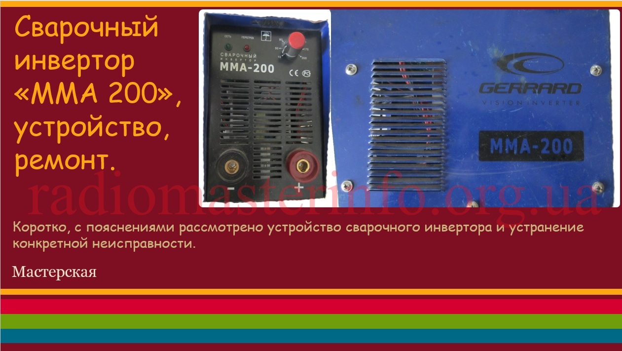
With the advent of powerful high-voltage transistors and diodes, welding inverters... Their main advantages: small dimensions, smooth adjustment of the welding current, overload protection. The weight of a welding inverter with a current of up to 250 Amperes is only a few kilograms.
Principle of operation welding inverter is clear from the following block diagram:
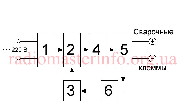
An alternating mains voltage of 220 V is supplied to a transformer-free rectifier and a filter (1), which forms a constant voltage of 310 V. This voltage supplies a powerful output stage (2). Pulses with a frequency of 40-70 kHz from a generator (3) are fed to the input of this powerful output stage. The amplified pulses are fed to a pulse transformer (4) and then to a powerful rectifier (5) to which the welding terminals are connected. The control and overload protection unit (6) regulates the welding current and protects.
Because inverter works at frequencies of 40-70 kHz and higher, and not at a frequency of 50 Hz, like a conventional welder, the dimensions and weight of its pulse transformer are ten times less than that of a conventional 50 Hz welding transformer. And the presence of an electronic control circuit allows you to smoothly regulate the welding current and provide effective overload protection.
Let's look at a specific example.
Inverter stopped cooking. The fan is running, the indicator is on, and the arc does not appear.
This type of inverter is quite common. This model is called "Gerrard MMA 200»
We managed to find a circuit of the MMA 250 inverter, which turned out to be very similar and helped significantly in the repair. Its main difference from the desired scheme MMA 200:
- The output stage has 3 field-effect transistors, connected in parallel, and the MMA 200 - by 2.
- Output pulse transformer 3, and at MMA 200 - only 2.
The rest of the scheme is identical.
At the beginning of the article, a description of the structural diagram of the welding inverter is given. It is clear from this description that welding inverter, this is a powerful switching power supply with an open-circuit voltage of about 55 V, which is necessary for the occurrence of a welding arc, as well as an adjustable welding current, in this case, up to 200 A. The pulse generator is made on a U2 microcircuit of the SG3525AN type, which has two outputs for control of subsequent amplifiers. The generator U2 itself is controlled through an operational amplifier U1 of the CA 3140 type. This circuit regulates the duty cycle of the generator pulses and thus the value of the output current set by the current control resistor brought out to the front panel.
From the output of the generator, the pulses are fed to a preamplifier made of bipolar transistors Q6 - Q9 and field workers Q22 - Q24 operating on a transformer T3. This transformer has 4 output windings which, through the formers, supply pulses to 4 arms of the output stage assembled in a bridge circuit.In each shoulder there are two or three powerful field workers in parallel. In the MMA 200 scheme - two each, in the MMA - 250 scheme - three each. In my case, the MMA-200 has two field-effect transistors of the K2837 (2SK2837) type.
From the output stage, powerful pulses are fed to the rectifier through transformers T5, T6. The rectifier consists of two (MMA 200) or three (MMA 250) full-wave midpoint rectifier circuits. Their outputs are connected in parallel.
A feedback signal is supplied from the rectifier output through connectors X35 and X26.
Also, the feedback signal from the output stage through the current transformer T1 is fed to the overload protection circuit, made on the thyristor Q3 and transistors Q4 and Q5.
The output stage is powered by a mains voltage rectifier assembled on a VD70 diode bridge, C77-C79 capacitors and forming a voltage of 310 V.
To power low-voltage circuits, a separate switching power supply is used, made on transistors Q25, Q26 and transformer T2. This power supply generates a voltage of +25 V, from which +12 V is additionally formed through U10.
Let's go back to the repair. After opening the case, a visual inspection revealed a burnt capacitor 4.7 μF at 250 V.
This is one of the capacitors through which the output transformers are connected to the output stage on the field workers.
The capacitor has been replaced and the inverter is working. All voltages are normal. After a few days, the inverter stopped working again.
A detailed examination revealed two broken resistors in the gate circuit of the output transistors. Their nominal value is 6.8 ohms, in fact they are in the cliff.
All eight output field effect transistors were tested. As mentioned above, they are included two in each shoulder. Two shoulders, i.e. four field workers, out of order, their leads are short-circuited. With such a defect, high voltage from the drain circuits enters the gate circuits. Therefore, the input circuits were tested. Defective elements were also found there. This is a zener diode and a diode in the pulse shaping circuit at the inputs of the output transistors.
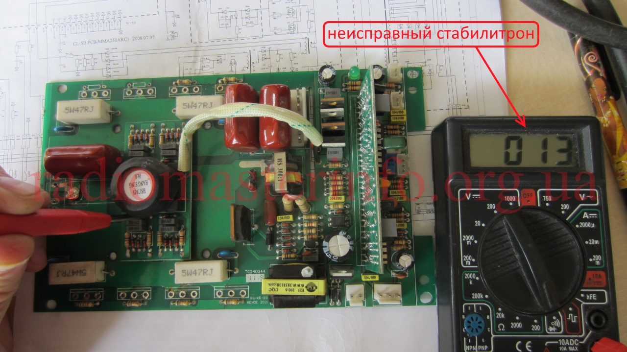
The check was carried out without soldering the parts by comparing the resistances between the same points of all four pulse shapers.
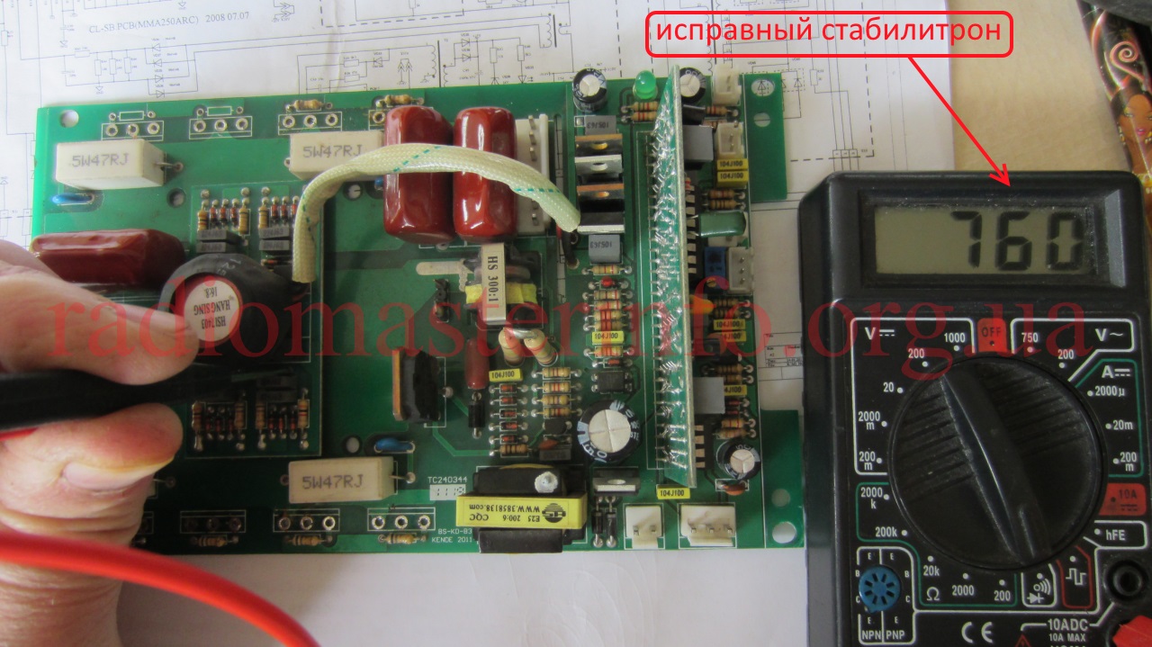
All other circuits were also tested up to the output terminals.
When checking the weekend field workers, all of them were soldered. The faulty ones, as mentioned above, turned out to be 4.
The first turn-on was done without any powerful field-effect transistors at all. With this turn on, the serviceability of all power supplies 310 V, 25 V, 12 V was checked. They are normal.
Voltage test points on the diagram:
Checking the 25V voltage on the board:
Checking the 12V voltage on the board:
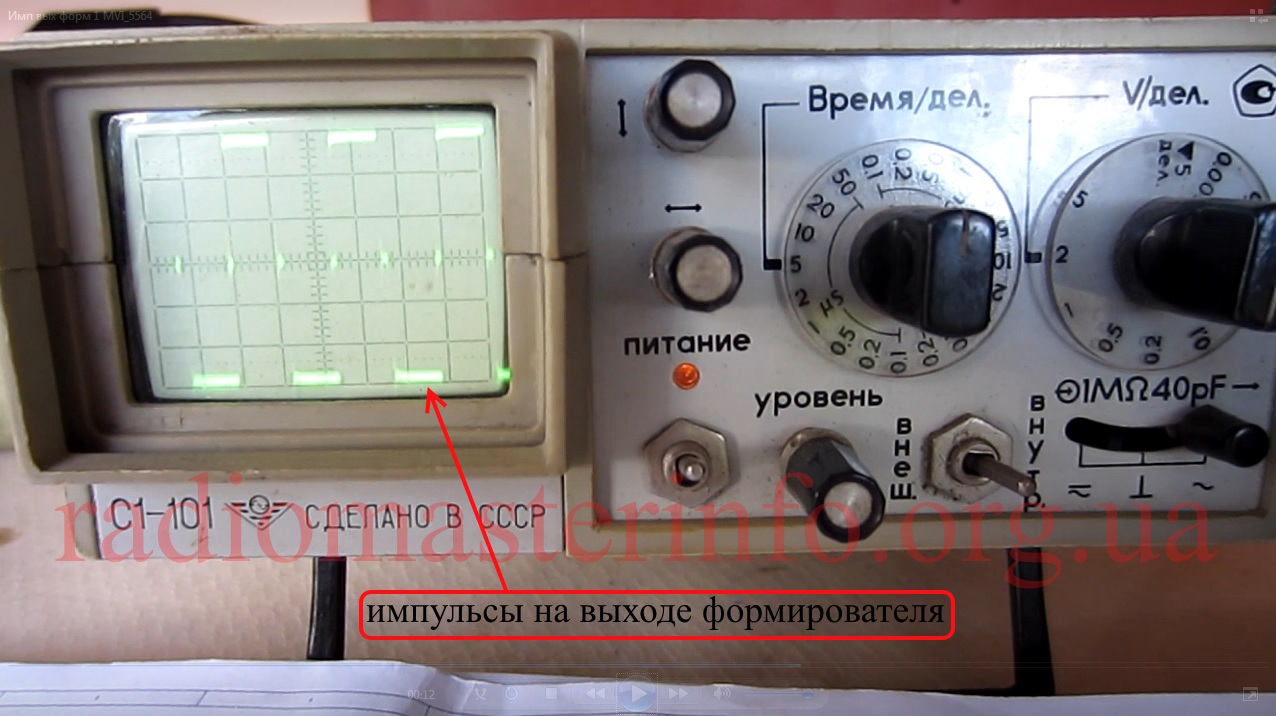
After that, the pulses at the outputs of the pulse generator and at the outputs of the shapers were checked.
Pulses at the output of the shapers, in front of the powerful field-effect transistors:
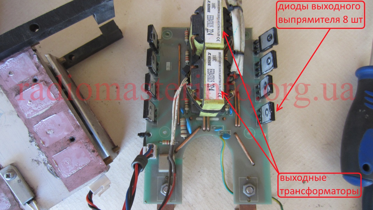
Then all the rectifier diodes were checked for leakage. Since they are connected in parallel and a resistor is connected to the output, the leakage resistance was about 10 kΩ. When checking each individual diode, the leakage is more than 1 mΩ.
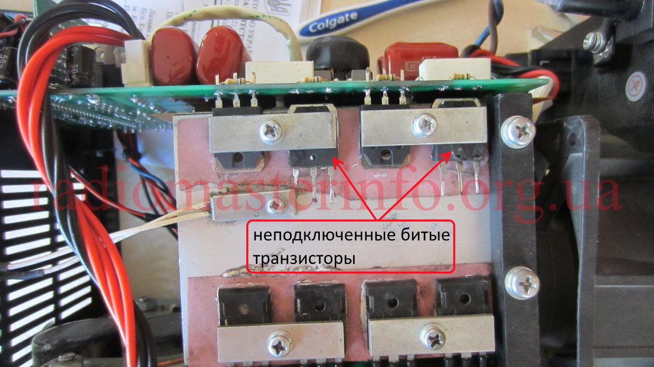
Further, it was decided to assemble the output stage on four field-effect transistors, placing not two, but one transistor in each arm. Firstly, the risk of failure of the output transistors, although it is minimized by checking all other circuits and the operation of power supplies, still remains after such a malfunction. In addition, it can be assumed that if there are two transistors in the arm, then the output current is up to 200 A (MMA 200), if there are three transistors, then the output current is up to 250 A, and if there is one transistor each, then the current may well reach 80 A. This means that when installing one transistor in the shoulder, you can cook with electrodes up to 2 mm.
It was decided to make the first control short-term switching on in the XX mode through a 2.2 kW boiler.This can minimize the consequences of an accident if, after all, some kind of malfunction was missed. In this case, the voltage at the terminals was measured:
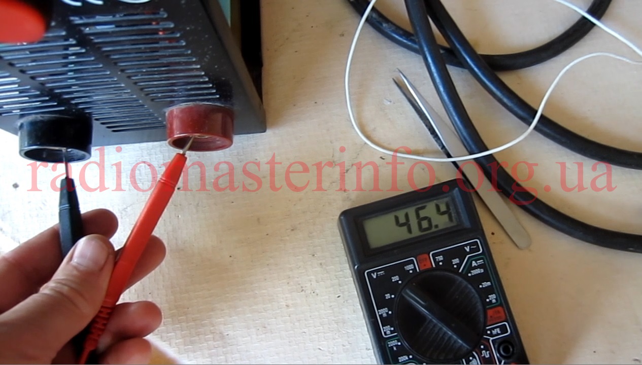
Everything works fine. Only the feedback and protection circuits were not tested. But the signals of these circuits appear only when there is a significant output current.
Since the switching on was normal, the output voltage is also within the normal range, we remove the series-connected boiler and turn on the welding directly to the network. Check the output voltage again. It is slightly higher and within 55 V. This is quite normal.
We try to cook for a short time, while observing the operation of the feedback circuit. The result of the operation of the feedback circuit will be a change in the duration of the generator pulses, which we will observe at the inputs of the transistors of the output stages.
When the load current changes, they change. This means the circuit is working correctly.
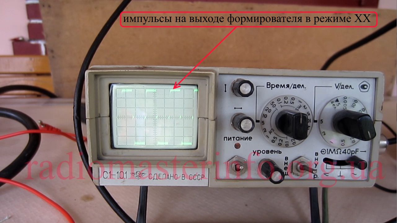
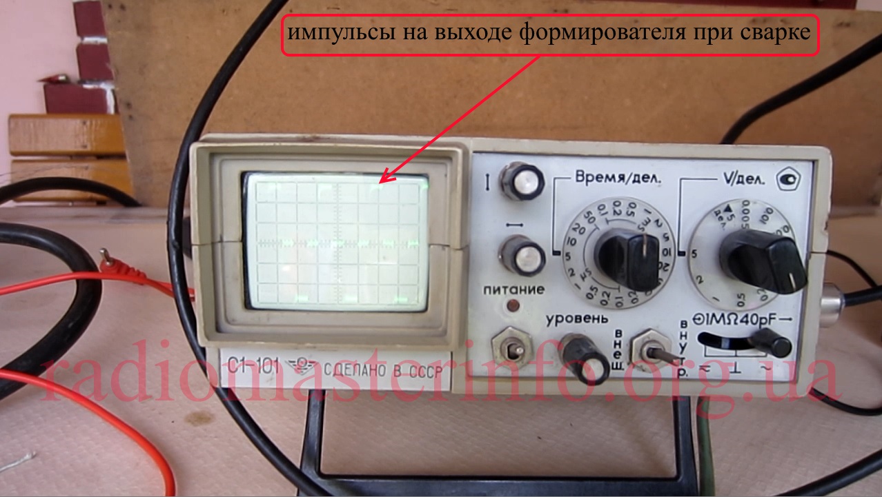
Missing output transistors can be purchased and replaced.
The article material is duplicated on video:
Inverter welding machines are gaining more and more popularity among master welders due to their compact size, low weight and reasonable prices. Like any other equipment, these devices can fail due to improper operation or due to design flaws. In some cases, the repair of inverter welding machines can be carried out independently by examining the inverter device, but there are breakdowns that are eliminated only at the service center.
Welding inverters, depending on the models, operate both from a household electrical network (220 V) and from a three-phase (380 V). The only thing to consider when connecting the device to a household network is its power consumption. If it exceeds the capabilities of the wiring, then the unit will not work with a sagging network.
So, the following main modules are included in the device of an inverter welding machine.
Just like diodes, transistors are installed on radiators for better heat dissipation from them. To protect the transistor unit from voltage surges, an RC filter is installed in front of it.
Below is a diagram that clearly shows the principle of operation of the welding inverter.
So, the principle of operation of this module of the welding machine is as follows. The primary rectifier of the inverter is supplied with voltage from the household electrical network or from generators, gasoline or diesel. The incoming current is alternating, but passing through the diode block, becomes permanent... The rectified current is fed to the inverter, where it is converted back to alternating current, but with changed frequency characteristics, that is, it becomes high-frequency. Further, the high-frequency voltage is reduced by a transformer to 60-70 V with a simultaneous increase in the current strength. At the next stage, the current again enters the rectifier, where it is converted to DC, after which it is supplied to the output terminals of the unit. All current conversions controlled by a microprocessor control unit.
Modern inverters, especially those based on the IGBT module, are quite demanding on the rules of operation. This is explained by the fact that when the unit is operating, its internal modules give off a lot of heat... Although both radiators and a fan are used to remove heat from power units and electronic boards, these measures are sometimes not enough, especially in inexpensive units. Therefore, you need to strictly follow the rules that are indicated in the instructions for the device, implying periodic shutdown of the installation for cooling.
This rule is usually referred to as the “Duty Cycle” (Duty Cycle), which is measured as a percentage.Not observing the PV, overheating of the main units of the apparatus occurs and their failure occurs. If this happens with a new unit, then this breakdown is not subject to warranty repair.
Also, if the inverter welding machine is working in dusty rooms, dust settles on its radiators and interferes with normal heat transfer, which inevitably leads to overheating and breakdown of electrical components. If it is impossible to get rid of the presence of dust in the air, it is necessary to open the inverter case more often and clean all the components of the device from accumulated dirt.
But most often inverters fail when they work at low temperatures. Breakdowns occur due to the appearance of condensation on the heated control board, as a result of which a short circuit occurs between the parts of this electronic module.
A distinctive feature of inverters is the presence of an electronic control board, therefore, only a qualified specialist can diagnose and eliminate a malfunction in this unit.... In addition, diode bridges, transistor blocks, transformers and other parts of the electrical circuit of the apparatus can fail. To carry out diagnostics with your own hands, you need to have certain knowledge and skills in working with measuring instruments such as an oscilloscope and a multimeter.
From the above, it becomes clear that, without the necessary skills and knowledge, it is not recommended to start repairing the device, especially electronics. Otherwise, it can be completely disabled, and repairing the welding inverter will cost half the cost of a new unit.
As already mentioned, inverters fail due to external factors affecting the “vital” units of the apparatus. Also, malfunctions of the welding inverter can occur due to improper operation of the equipment or errors in its settings. The most common malfunctions or interruptions in inverter operation are as follows.
Very often, this breakdown is caused by faulty network cable apparatus. Therefore, first you need to remove the cover from the unit and ring each wire of the cable with a tester. But if everything is in order with the cable, then more serious diagnostics of the inverter will be required. Perhaps the problem lies in the standby power source of the device. The repair technique for the “duty room” using the example of a Resant brand inverter is shown in this video.
This malfunction can be caused by an incorrect setting of the amperage for a certain diameter of the electrode.
You should also consider and welding speed... The smaller it is, the lower the current value must be set on the control panel of the unit. In addition, to match the current strength to the diameter of the additive, you can use the table below.
If the welding current is not regulated, the cause may be breakdown of the regulator or violation of the contacts of the wires connected to it. It is necessary to remove the cover of the unit and check the reliability of the connection of the conductors, and, if necessary, ring the regulator with a multimeter. If everything is in order with him, then this breakdown can be caused by a short circuit in the inductor or a malfunction of the secondary transformer, which will need to be checked with a multimeter. If a malfunction is found in these modules, they must be replaced or rewound to a specialist.
Excessive power consumption, even when the device is not loaded, most often causes turn-to-turn closure in one of the transformers. In this case, you will not be able to repair them yourself. It is necessary to take the transformer to the master for rewinding.
This happens if the voltage drops in the network... To get rid of the sticking of the electrode to the parts to be welded, you will need to correctly select and set up the welding mode (according to the instructions for the device). Also, the voltage in the network may sag if the device is connected to an extension cord with a small wire cross-section (less than 2.5 mm 2).
It is not uncommon for a voltage drop that causes the electrode to stick when using a power strip that is too long. In this case, the problem is solved by connecting the inverter to the generator.
If the indicator is on, this indicates overheating of the main modules of the unit. Also, the device can turn off spontaneously, which indicates tripping of thermal protection... So that these interruptions in the operation of the unit do not occur in the future, again, it is necessary to adhere to the correct mode of the duration of the on (DC). For example, if duty cycle = 70%, then the device should work in the following mode: after 7 minutes of operation, the unit will have 3 minutes to cool down.
In fact, there can be a lot of various breakdowns and the reasons that cause them, and it is difficult to list them all. Therefore, it is better to immediately understand what algorithm is used to diagnose the welding inverter in search of faults. You can find out how the device is diagnosed by watching the following training video.
Repair of welding inverters, despite its complexity, in most cases can be done independently. And if you are well versed in the design of such devices and have an idea of what is more likely to fail in them, you can successfully optimize the costs of professional service.
Replacement of radio components in the process of repairing a welding inverter
The main purpose of any inverter is to generate a constant welding current, which is obtained by rectifying a high-frequency alternating current. The use of a high-frequency alternating current, converted by means of a special inverter module from a rectified mains supply, is due to the fact that the strength of such a current can be effectively increased to the required value using a compact transformer. It is this principle underlying the operation of the inverter that allows such equipment to have compact dimensions with high efficiency.
Functional diagram of the welding inverter
The welding inverter circuit, which determines its technical characteristics, includes the following main elements:
- a primary rectifier unit, the basis of which is a diode bridge (the task of such a unit is to rectify an alternating current supplied from a standard electrical network);
- an inverter unit, the main element of which is a transistor assembly (it is with the help of this unit that the direct current supplied to its input is converted into an alternating current, the frequency of which is 50–100 kHz);
- a high-frequency step-down transformer, on which, due to a decrease in the input voltage, the output current is significantly increased (due to the principle of high-frequency transformation, a current can be generated at the output of such a device, the strength of which reaches 200–250 A);
- output rectifier, assembled on the basis of power diodes (the task of this block of the inverter includes rectifying an alternating high-frequency current, which is necessary for performing welding work).
The welding inverter circuit contains a number of other elements that improve its operation and functionality, but the main ones are the ones listed above.
Repair of an inverter-type welding machine has a number of features, which is explained by the complexity of the design of such a device. Any inverter, unlike other types of welding machines, is electronic, which requires specialists involved in its maintenance and repair to have at least basic radio engineering knowledge, as well as skills in handling various measuring instruments - a voltmeter, digital multimeter, oscilloscope, etc. ...
In the process of maintenance and repair, the elements that make up the welding inverter circuit are checked.This includes transistors, diodes, resistors, zener diodes, transformer and choke devices. The peculiarity of the design of the inverter is that very often during its repair it is impossible or very difficult to determine the failure of which particular element was the cause of the malfunction.
A sign of a burnt out resistor may be a small carbon deposit on the board, which is difficult to distinguish with an inexperienced eye.
In such situations, all the details are checked sequentially. To successfully solve such a problem, it is necessary not only to be able to use measuring instruments, but also to be quite familiar with electronic circuits. If you do not have such skills and knowledge at least at the initial level, then repairing a welding inverter with your own hands can lead to even more serious damage.
Realistically assessing their strengths, knowledge and experience and deciding to undertake independent repair of inverter-type equipment, it is important not only to watch a training video on this topic, but also to carefully study the instructions, in which manufacturers list the most typical malfunctions of welding inverters, as well as ways to eliminate them.
Situations that can cause the inverter to fail or lead to malfunctions can be divided into two main types:
- associated with the wrong choice of welding mode;
- caused by the failure of parts of the device or their incorrect operation.
The technique for detecting an inverter malfunction for subsequent repair is reduced to the sequential execution of technological operations, from the simplest to the most complex. The modes in which such checks are performed and what their essence is, is usually specified in the equipment instructions.
Common inverter malfunctions, their causes and remedies
If the recommended actions did not lead to the desired results and the operation of the device has not been restored, most often this means that the cause of the malfunction should be looked for in the electronic circuit. The reasons for the failure of its blocks and individual elements may be different. Let's list the most common ones.
- Moisture has penetrated into the interior of the device, which can happen if precipitation falls on the body of the device.
- Dust has accumulated on the elements of the electronic circuit, which leads to a violation of their full cooling. The maximum amount of dust gets into inverters when they are used in highly dusty rooms or on construction sites. In order not to bring the equipment to such a state, its interior must be regularly cleaned.
- Overheating of the elements of the electronic circuit of the inverter and, as a consequence, their failure can lead to non-observance of the duration of the switch (DC). This parameter, which must be strictly observed, is indicated in the technical passport of the equipment.
Liquid traces inside the inverter housing
The most common problems encountered when operating inverters are as follows.
Unstable arc burning or active metal spatter
This situation may indicate that the wrong amperage has been selected for welding. As you know, this parameter is selected depending on the type and diameter of the electrode, as well as on the speed of welding. If the packaging of the electrodes that you are using does not contain recommendations on the optimal value of the current strength, you can calculate it using a simple formula: 1 mm of the electrode diameter should account for 20–40 A of welding current. It should also be borne in mind that the lower the welding speed, the lower the current should be.
Dependence of the diameter of the electrodes on the strength of the welding current
This problem can be associated with a number of reasons, and most of them are based on undervoltage.Modern models of inverter devices also operate at reduced voltage, but when its value drops below the minimum value for which the equipment is designed, the electrode begins to stick. A drop in the voltage value at the output of the equipment can occur if the device blocks do not contact the panel sockets poorly.
This reason can be eliminated very simply: by cleaning the contact sockets and fixing the electronic boards in them more tightly. If the wire through which the inverter is connected to the mains has a cross-section of less than 2.5 mm2, this can also lead to a voltage drop at the input of the device. This is guaranteed to happen even if such a wire is too long.
If the length of the supply wire exceeds 40 meters, it is practically impossible to use an inverter for welding, which will be connected with its help. The voltage in the supply circuit can also drop if its contacts are burnt or oxidized. A frequent cause of electrode sticking is insufficiently high-quality preparation of the surfaces of the parts to be welded, which must be thoroughly cleaned not only from the existing contaminants, but also from the oxide film.
Selection of the cross-section of the welding cable
This situation often occurs in the event of overheating of the inverter device. At the same time, the control indicator on the panel of the device should light up. If the glow of the latter is hardly noticeable, and the inverter does not have a sound alert function, then the welder may simply not be aware of overheating. This state of the welding inverter is also typical when the welding wires are broken or spontaneously disconnected.
Spontaneous shutdown of the inverter during welding
Most often, this situation occurs when the supply of the supply voltage is turned off by circuit breakers whose operating parameters are incorrectly selected. When working with an inverter device, automatic machines designed for a current of at least 25 A must be installed in the electrical panel.
Most likely, this situation indicates that the voltage in the power supply network is too low.
Automatic shutdown of the inverter during prolonged welding
Most modern inverter machines are equipped with temperature sensors that automatically turn off the equipment when the temperature in its interior rises to a critical level. There is only one way out of this situation: give the welding machine a rest for 20-30 minutes, during which it will cool down.
If after testing it becomes clear that the cause of malfunctions in the operation of the inverter device lies in its inner part, you should disassemble the case and start examining the electronic filling. It is possible that the reason lies in poor-quality soldering of device parts or poorly connected wires.
A close inspection of the electronic circuits will reveal faulty parts that may be darkened, cracked, bloated, or have burnt contacts.
Burnt parts on the Fubac IN-160 inverter board (AC-DC regulator, 2NK90 transistor, 47 ohm resistor)
During repair, such parts must be removed from the boards (it is advisable to use a soldering iron with a suction for this), and then replaced with similar ones. If the marking on the defective elements is not readable, then special tables can be used to select them. After replacing defective parts, it is advisable to test the electronic boards using a tester. Moreover, this must be done if the inspection did not reveal the elements to be repaired.
A visual check of the electronic circuits of the inverter and their analysis with a tester should start with the power unit with transistors, since it is he who is the most vulnerable. If the transistors are faulty, then, most likely, the circuit that shakes them (driver) has also failed.The elements that make up such a circuit must also be checked first.
After checking the transistor unit, all other units are checked, for which a tester is also used. The surface of the printed circuit boards must be carefully examined to determine the presence of burnt areas and breaks on them. If any are found, then such places should be carefully cleaned and jumpers should be soldered on them.
If burnt or broken wires are found in the filling of the inverter, then during repair they must be replaced with similar ones in cross section. Although the diode bridges of the inverter rectifiers are reliable enough, they should also be ringed with a tester.
The most complex element of the inverter is the key control board, the operability of which depends on the operability of the entire device. Such a board for the presence of control signals that are fed to the gate buses of the key block is checked using an oscilloscope. The final stage in testing and repairing the electronic circuits of the inverter device should be to check the contacts of all existing connectors and clean them with a regular eraser.
Self-repair of an electronic device such as an inverter is quite difficult. It is almost impossible to learn how to repair this equipment just by watching a training video, for this you need to have certain knowledge and skills. If you have such knowledge and skills, then watching such a video will give you the opportunity to make up for the lack of experience.
| Video (click to play). |


