In detail: do-it-yourself repair of a 2n125 drilling machine from a real master for the site my.housecope.com.
Manufacturer of vertical drilling machines models 2Н125, 2Н135, 2Н150, 2Г175 - Sterlitamak Machine-Tool Plant, NPO Machine-Tool Building LLC, founded in 1941.
The history of the Sterlitamak machine-tool plant begins on July 3, 1941, when the evacuation of the Odessa machine-tool plant to the city of Sterlitamak began.
Already on October 11, 1941, the Sterlitamak Machine-Tool Plant began to produce special modular machine tools for the defense industry.
Currently, the plant produces metalworking equipment, including CNC turning and milling machines, multifunctional machining centers, metalworking and cutting tools.
Universal vertical drilling machine 2H125, with a nominal drilling diameter of 25 mm, is used at enterprises with a single and small-scale production of products and is designed to perform the following operations: drilling, reaming, countersinking, countersinking, reaming and trimming the ends with knives.
The limits of the number of revolutions and spindle feeds allow processing various types of holes at rational cutting conditions.
Chronology the plant's production of vertical drilling machines series 2125 with a drilling diameter of up to 25 mm:
- 2125 - the first model of a series of vertical drilling machines, produced from 1945 to 1950.
- 2A125, 2A125A, 2A125K - the following models of the series, produced from 1950 to 1965
- 2N125, 2N125A, 2N125K, 2N125F2 - the most popular and mass-produced model of the series, produced from 1965 to the beginning of the 90s
- 2S125, 2S125-01, 2S125-04 - the latest models of the series. Discontinued in 2014
| Video (click to play). |
The presence of mechanical spindle feed on machines, with manual control of work cycles.
Allows processing of parts in a wide range of sizes from various materials using tools from high-carbon and high-speed steels and hard alloys.
The machines are equipped with a device for reversing the electric motor of the main movement, which allows them to be threaded with machine taps with manual spindle feed.
Placement category 4 in accordance with GOST 15150-69.
Developer - Odessa Special Design Bureau of Special Machine Tools.
Basic vertical drilling machines are used to process holes of different diameters: 2H125... The last two digits of each model number indicate the largest hole diameter in mm that can be drilled on this machine in 45 steel blanks.
Based on the above basic models of machine tools, the following modified models have been created:
2N125A - vertical drilling machines with automated control (control is performed using preset cams and buttons);
2N125K - coordinate vertical drilling machines with a cross table;
2N125S - special single-position vertical drilling machines with a flange quill, which serves for fastening multi-spindle heads;
2Н125Н - multi-position drilling machines designed for the installation of multi-spindle heads and rotary tables;
2N125F2 - CNC drilling machines, cross table and turret, etc.
- 2T125, 2T140, 2T150 - manufacturer: Gomel plant of machine tool units
- 2АС132, 2АС132-01 - manufacturer: Astrakhan machine-tool plant
- 2L125, 2L132, 2L135, LS25, LS35 - manufacturer: Lipetsk machine-tool plant (PJSC STP-LSP)
- MN25L, MN25N-01 - manufacturer: Molodechno machine-tool plant
Drawing of the working space of the drilling machine 2H125
Photo of drilling machine 2Н125
Location of the main parts of the drilling machine 2H125
- Drilling machine drive - 2H125.21.000
- Machine speed box - 2H125.20.000
- Oil plunger pump - 2N125.24.000 for machine 2N125
- Oil plunger pump - 2Н135.24.000
- Feed box - 2Н125.30.000
- Column, table, plate - 2N125.10.000
- Speed and feed control mechanism - 2H125.25.000
- Electrical cabinet - 2N125.72.000
- Electrical equipment - 2N125.94.000
- Spindle assembly - 2H125.50.000
- Cooling system of the machine - 2H125.80.000
- Drilling head - 2H125.40.000
Arrangement of controls for drilling machine 2H125
- Label - "Filling" coolant
- Plate - "Drain"
- Cooling switch
- + 19 Bolts for adjusting the table wedge and drill head
- Handle for moving the table
- Table clamp and drill head screws
- Label - "Grounding"
- Opening switch
- Decal - "Main switch"
- Signal button MACHINE ON
- Button for turning on the right spindle rotation
- Left spindle rotation button
- Button for turning on the rocking motion of the spindle when switching speeds and feeds
- Gearshift knob
- STOP button
- Plate - "Speed"
- Decal - "Change speed only when stopping"
- Table clamp and drill head screws
- +4 Bolts for adjusting the table wedge and drill head
- Plate - "Feed, mm per one revolution"
- Feed switch handle
- Manual feed button
- Handwheel of the feed mechanism
- Limb for reading the working depth
- Light switch
- Label - "Cooling"
- Cooling pump switch
- Cam for setting the working depth
- Cam for setting the depth of the thread to be cut
- Lever for automatic reversal of the main drive when the specified depth of the cut thread is reached
- Lever for shutting off the mechanical feed when reaching the specified working depth
- Square for manual movement of the drill head
Kinematic diagram of the drilling machine 2H125
List of graphic symbols on the drilling machine 2H125
Drawing of the gearbox of the drilling machine 2N125
Gearbox and drive. The gearbox informs the spindle of 12 different speeds by means of movable blocks 5 (Fig. 7), 7, 8. The shaft supports of the box are placed in two plates - the upper and the lower 4, fastened together by four ties 6. The gearbox is rotated vertically an electric motor through an elastic coupling 10 and a gear train 9. The last shaft 2 of the box - the sleeve - has a spline hole through which rotation is transmitted.
Through gear pair 3, rotation is transmitted to the feed box.
Lubrication of the gearbox, like all assembly units of the drilling head, is made from a plunger pump fixed on the lower plate 4. The pump operation is controlled by a special oil indicator on the front of the sub-engine plate.
The mechanism for controlling the speeds and feeds of the drilling machine 2H125
The mechanism for switching the speeds and feeds of the drilling machine 2H125
Mechanism for switching speeds and feeds... The gears are switched by handle 2 (Fig. 8), which has four positions around the circumference and three along the axis, feed switching is carried out by handle 3, which has three positions around the circumference for machine models 2H135 and four for 2H150, and three positions along the axis. The handles are located on the front of the drill head. The counting of the included speeds and feeds is carried out according to tables 1 and 4.
Drilling machine feed box drawing 2N125
Gearbox. The mechanism is mounted in a separate housing and installed in the drill head. Due to the movement of two triple gear blocks, nine different feeds are carried out on the 2H125, 2H135 machines and twelve feeds on the 2H150 machine. On 2H125 and 2H135 machines, the feed boxes differ only in the drive, which consists of gears 1 on the 2H125 machine (Fig. 9), on 2H125, 2H135 machines - of gears 2, 3 - respectively.The feed box is mounted in the bore of the upper support of the feed mechanism worm. On the last shaft of the box, there is a clutch 4, which transfers the rotation to the worm.
Drawing of the drilling head of the drilling machine 2H125
Drill head is a box-section casting, in which all the main assembly units of the machine are mounted: a gearbox, a gearbox, a spindle, a feed mechanism, a spindle counterweight and a mechanism for switching speeds and feeds.
Feed mechanismconsisting of a worm gear, a horizontal shaft with a rack and pinion gear, a dial, a cam and ratchet overrunning clutches, a steering wheel, is an integral part of the drilling head.
The feed mechanism is driven by the feed box and is designed to perform the following operations:
- manual approach of the tool to the part;
- switching on the working feed;
- manual feed advance;
- turning off the working feed;
- manual retraction of the spindle up;
- manual feed used when threading.
The principle of operation of the feed mechanism is as follows: when the handwheel 14 (Fig. 10) rotates, the cam clutch 8 rotates towards itself, which rotates the pinion shaft 3 of the rack and pinion through the cage-half-clutch 7, and the spindle is manually fed. When the tool approaches the part, a torque arises on the pinion shaft 3, which cannot be transmitted by the teeth of the cam clutch 8, and the half-clutch cage 7 moves along the shaft until the ends of the cams of parts 7 and 8 come against each other. At this moment, the cam clutch 8 rotates relative to the pinion shaft 3 at an angle of 20 °, which is limited by the groove in the part 8 and the pin 10. On the cage - half-clutch 7, there is a double-sided ratchet disc 6 connected to the half-clutch by pawls 13. When moving the cage-half-clutch 7 the teeth of the disc 6 mesh with the teeth of the disc, made integral with the worm wheel 5. As a result, the rotation from the worm is transmitted to the rack gear and the spindle is mechanically fed. With further rotation of the steering wheel 14 with the feed turned on, the pawls 13, sitting in the half-coupling 7, slip along the teeth of the inner side of the disc 6; there is a manual advance of the mechanical feed.
When manually turning on the feed by the handwheel 14 (after turning it towards itself at an angle of 20 °), the tooth of the clutch 8 stands against the cavity of the half-clutch clip 7. Due to the axial force and a special spring 12, the half-clutch clip 7 is shifted to the right and disengages the toothed discs 5 and 6; mechanical feed stops.
The feed mechanism allows manual spindle feed. To do this, turn off the mechanical feed with the handwheel 14 and move the cap 9 along the axis of the gear shaft 3 away from you. In this case, the pin II transmits the torque from the cam clutch 8 to the horizontal shaft. On the left wall of the drilling head, a limb 4 is mounted for visual reading of the depth after machining and adjusting the cams.
For manual movement of the drill head along the guides of the column, there is a mechanism that consists of a worm pair 2 and a rack and pinion pair I. To protect the feed mechanism from breakage, there is a safety clutch 15. Nut 16 and screw 17 are used to adjust the spring counterweight.
Spindle assembly of vertical drilling machine 2H125
Spindle 2 (Fig. 11) is mounted on two. The axial feed force is taken up by the lower thrust bearing, and the tool knockout force is taken up by the upper one. The bearings are located in the sleeve 3, which moves along the axis with the help of a rack and pinion pair. The spindle bearings are adjusted with nut 1.
A special device on the spindle head is used to knock out the tool. Knockout occurs when the spindle is lifted by the handwheel. The holder of the device abuts against the housing of the drilling head, and the lever 4, turning around the axis; knocks out the tool.
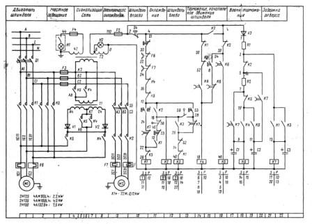
Electrical diagram of the drilling machine 2H125
Description of the work of the electrical circuit of the machine
Turning on the input circuit breaker B1 energizes the main and auxiliary circuits, the signal lamp lights up.If cooling and lighting is required, then the corresponding switches are placed in the "ON" position. By pressing the Kn2 "RIGHT" button, the starter coil P1 receives power, the main contacts turn on M1 to the right rotation of the spindle. Through the P1 block contacts, the P5 starter is switched on, which turns on the M2 electric pump and the P12 delay relay.
When you press the SC "LEFT" button, the P1 starter, the M1 electric motor, the P12 relay are disconnected after the capacitor C3 is discharged, the contacts of the P12 (28-26) relay are closed and the P2 and M1 starters are turned on for left rotation. Relay P12 switches on again.
With automatic reverse, these switching occurs when the microswitch B4 is triggered from the cam mounted on the dial.
The stop is carried out by pressing the button Kn1 "STOP", while the starters P1 or P2, P5 are turned off, disconnecting M1, M2. Through the contacts of the P12 relay (7-9), the P11 relay is switched on, followed by the switching on of the P3 and P4 starters. The windings of the M1 electric motor are connected through the rectifiers D1, D2 to the transformer Tr2, dynamic braking takes place. After the discharge of the capacitor C1, C2, the P11 relay turns off, disconnecting the P3, P4 and M1 starters from the brake circuit.
When switching speeds, if the gears do not engage, step rotation of the electric motor rotor is used. Pressing the button Kn4 "PROVOROT" turns on the P4 starter, a reduced rectified voltage flows through the phases 1C2-1CЗ. Relay P11 turns on with a delay through resistance P2, turning off starter P4 and turning on P3 - voltage flows through phases 1C1-1C2. Such shifts provide rotor and kinematics swinging, which facilitates gear shifting.
Thermal relays are used for overload protection. For zero protection - coils and contacts of magnetic starters.
Pages 1 2 3 Next
You must login or register to post a response.
- Jedi Knight
- Where: Kostroma
- Registration: 23-05-2011
- Posts: 1,010
I pulled a drilling machine out of ferrous metal. I didn't take a lot of things, I cleaned it, anointed it, connected it to the network, everything works in principle, but there is one thing. When the automatic feed is turned on, the spindle moves normally in the air, as soon as it starts to enter the metal, the feed is turned off. I tried different combinations of speeds, the result is the same.
When drilling a piece of wood, there is no such trouble
There is heat flux, but it has been cut off for now. I say that the problem is not in the electrics, there is one motor for rotation and for lowering, it is now connected directly to 380v through a conventional machine. The rotation does not stop, only the lowering stops.
Magic ferrous metal.
If it's not a secret, how much did the salvation cost?
I don’t know for sure yet, the person designated 25 r / kg, the machine has not yet been weighed, but on the Internet it weighs about 600 kg.
And really magical, now you can't buy anything worthwhile for that kind of money. Something similar will cost many times more.
Before that, I bought a fully working lathe for 15 tr. including transportation. its weight is 1.3 tons)
Before that, I bought a fully working lathe for 15 tr. including transportation. its weight is 1.3 tons)
Unreal luck. It's just unreal.
Does this often appear there ?! I would like to monitor the situation on these things somehow. I don’t even know how.
Do you install all this in your garage-workshop?
- PVS
- Jedi Master
- Where: Sverdlovsk
- Registration: 15-06-2011
- Posts: 14,334
So you need to make a manual feed
- Jedi Knight
- Where: Kostroma
- Registration: 23-05-2011
- Posts: 1,010
So you need to make a manual feed
Before that, I bought a fully working lathe for 15 tr. including transportation. its weight is 1.3 tons)
Unreal luck. It's just unreal.
Does this often appear there ?! I would like to monitor the situation on these things somehow. I don’t even know how.
Do you install all this in your garage-workshop?
These are things from different places. Just a coincidence.
No, I have a metalwork shop. I rent a room.
previously rented a room with a number of machines.I wanted to buy something back, they didn’t give it away, now it’s all lying around on the street, but still they don’t give anything back.
still don’t give anything away
The whole point of an inept manager. Fuck such a tool. They only know how to rent out and have babos out of it. And the mind to master the available equipment is not enough.
I look at YouTube, in Ufa the same crap, a former plant with machines stands, which are real dofig worth. You can buy back at the price of metal. Only delivery will be expensive, I guess. If necessary, I will contact the person who works there / makes / removes blogs.
There are not only lathes, there are some very highly specialized ones, such as a press for fierce tons and all that. I don’t remember exactly. A huge pile of belts piled up in a separate room.
I certainly don't know, but why do you need this feed? I have never used my feed. It has an eternal problem, it's grease. If your grease does not flow and a couple of: spindle - quill without backlash, good luck.
Pages 1 2 3 Next
You must login or register to post a response.
Message # 1 Alex72 »02 Jan 2018, 12:43
Message # 2 ROW »02 Jan 2018, 12:48
Message # 3 Salnik1970 »02 Jan 2018, 13:20
Message # 4 vanek-in1 »02 Jan 2018, 17:12
Message # 5 Machine operator »02 Jan 2018, 18:16
Message # 6 Salnik1970 »02 Jan 2018, 21:09
Message # 7 Alex72 »03 Jan 2018, 13:01
Thanks ! Tell. Which side is the best side to open the side cover? What would be better to get close to this spring
Sent after 2 minutes 31 seconds:
Message # 8 Salnik1970 »03 Jan 2018, 13:41
Message # 9 vanek-in1 »03 Jan 2018, 13:42
Message # 10 Alex72 »06 Jan 2018, 01:56
I opened it today from the side of the limb. Pulled out the flange. Attached to it with two bolts. Some kind of spring mechanism. with a yoke. The sun gear remained on the flange. It includes a small gear. Which is on the shaft of the steering wheel itself. Raised the quill manually. Supported. and Collected everything. The quill does not fall. Fine. But she also does not return to the top.
I am reading. what's in the curbstone. ... As far as I understand. There is a chain with a weight to return the quill up.
And another question: Prompt the device of the cap on the 125k wheel. I'm lost.
How difficult is it to make it yourself?
Sent after 2 minutes 53 seconds:
A little background. I worked for some time in a repair shop for high-pressure fuel pumps (high-pressure fuel pumps), and there was an abandoned drilling machine on the second floor, that is, a drilling machine. The owner took her away to hell, buying her, in his opinion, "an adequate replacement." To my question, what is the matter with her, he replied that the quill hits and it is no longer possible for her to drill.
Walking around the machine, I realized that the owner, luckily for me, was full
the dummy was wrong and the problem was the bearings. But I didn’t tell him about it, but simply offered to buy this “stuff” from him at the price of scrap, to which he, in fact, quickly agreed. Thus, I became the proud owner of a drilling machine at the end of the 60s, weighing that way under 150 kilograms, its column is cast, one-piece, Morse taper No. 2 in quills and a kilowatt motor. In short, quite a small industrial machine.
I quickly phoned a friend with a semi-truck and we, until no one changed his mind, took it apart into more digestible pieces, loaded it into a car and brought it to my home on my workshop balcony.
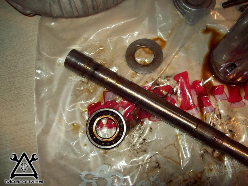
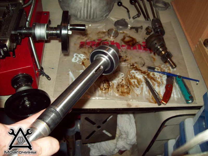
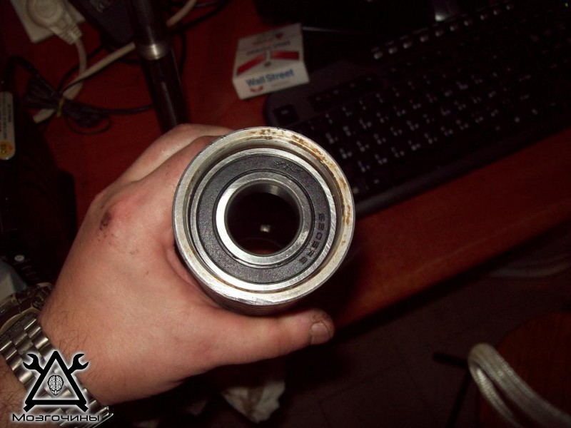
This was followed by: flushing everything from old grease, cleaning from old paint, replacing bearings with new closed ones (clogged with grease from the manufacturer).
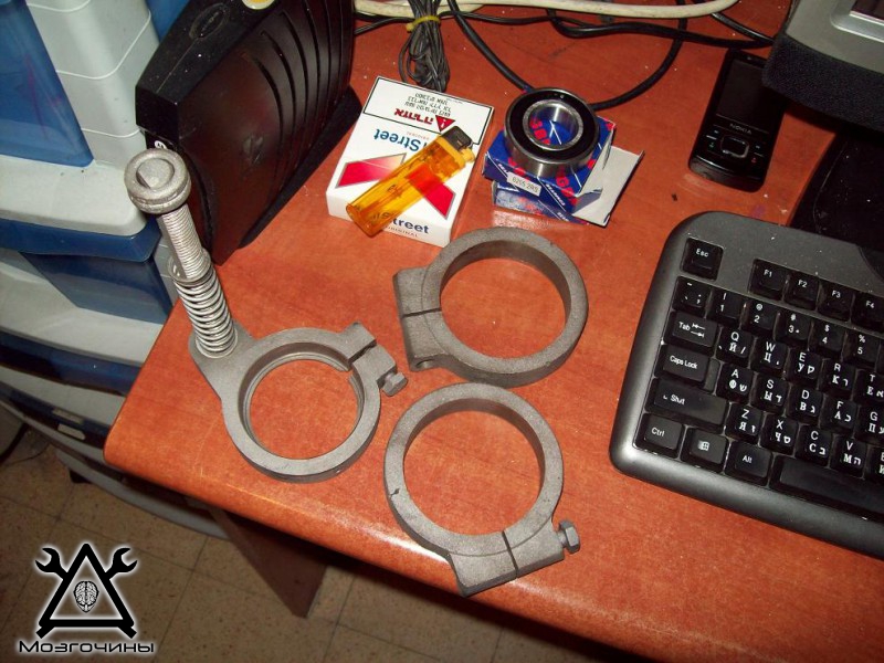
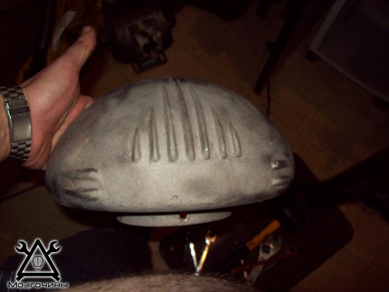
"Clean hat" - belt guard:
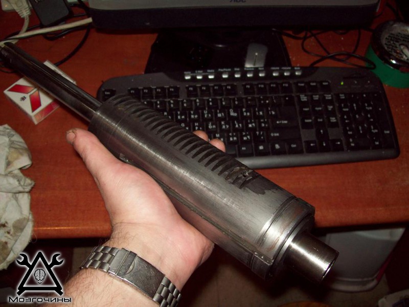
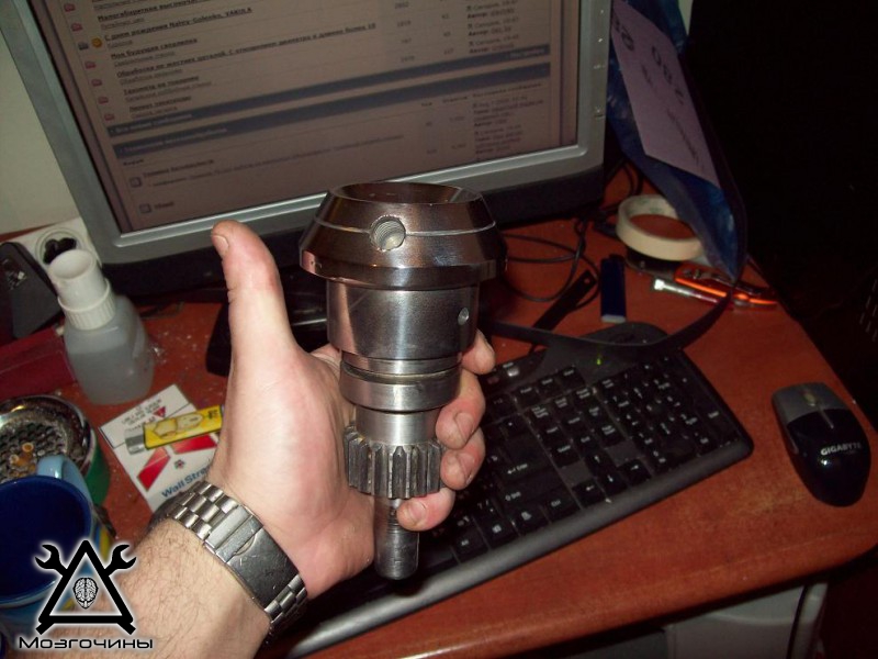
Quill assembly already with new bearings:
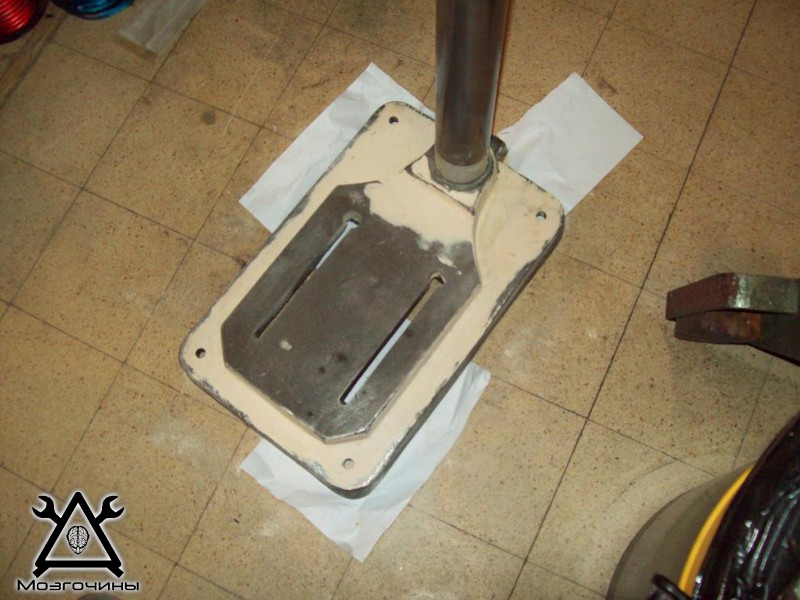
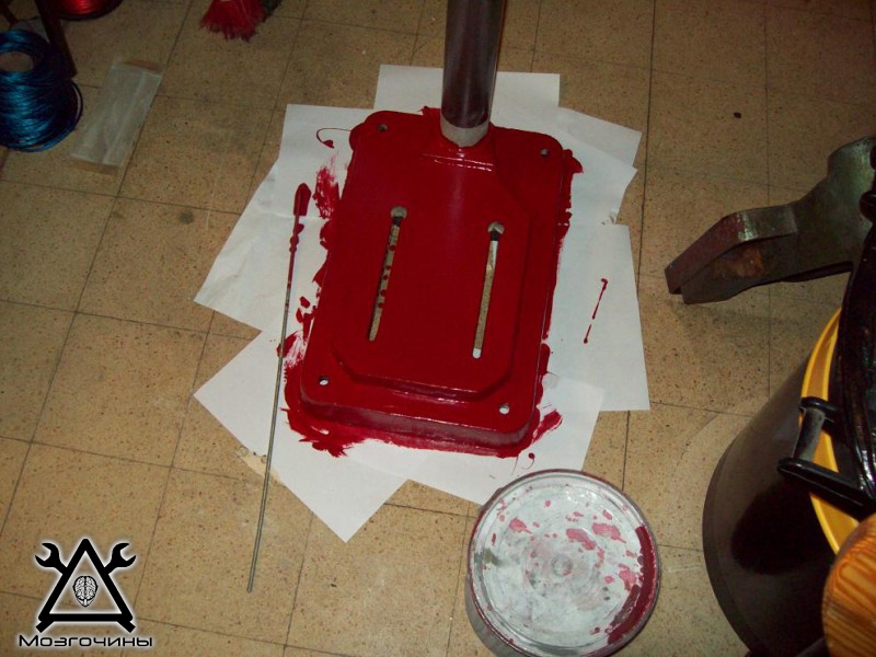
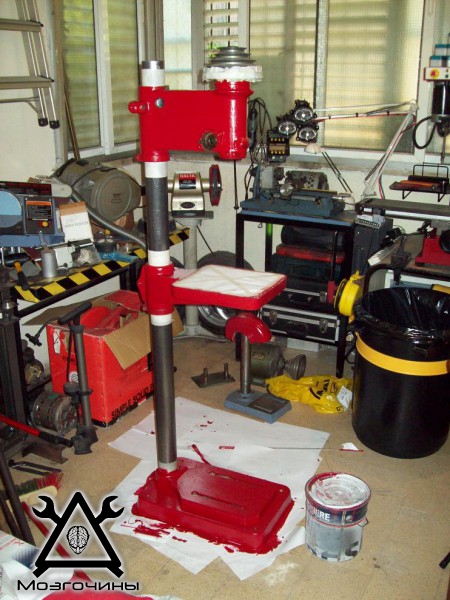
At the same time, puttying and painting of the machine was carried out:
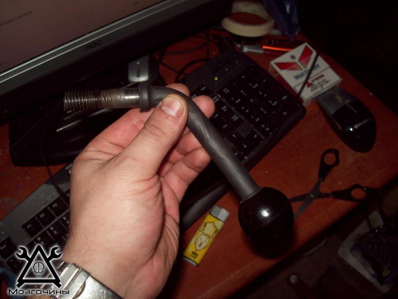
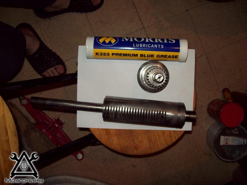
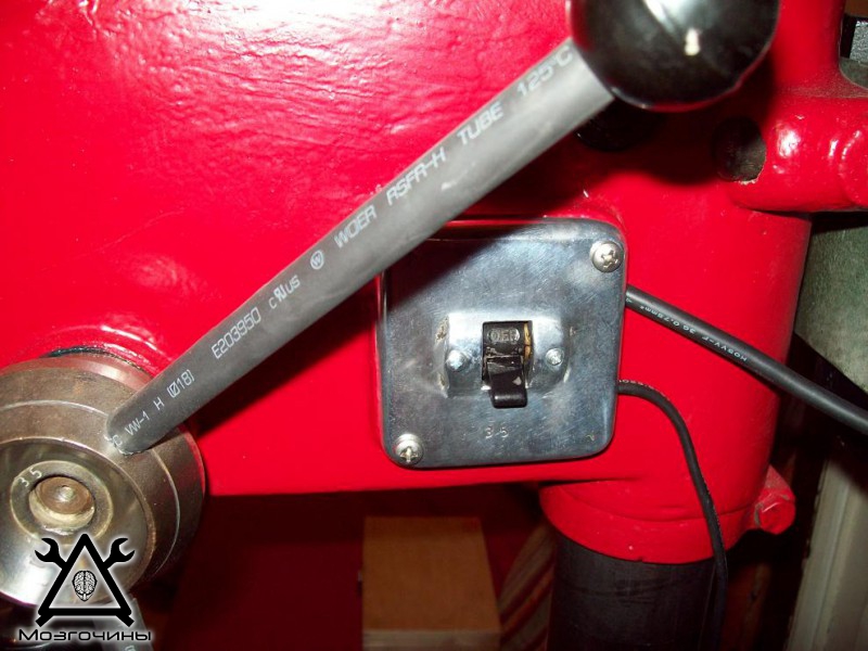
The last parts were washed, heat shrinks were put on the handles for a more aesthetic look, grease (grease) was bought and everything is ready for final assembly:
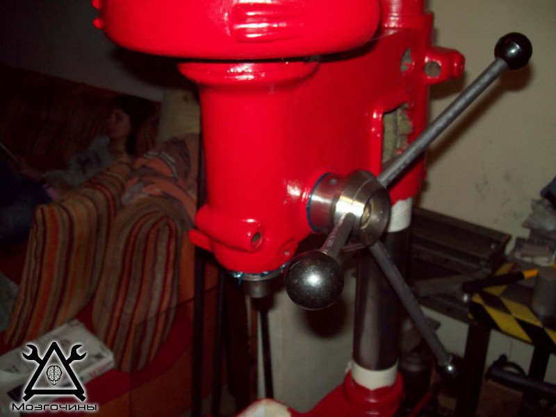
Slowly everything falls into place:
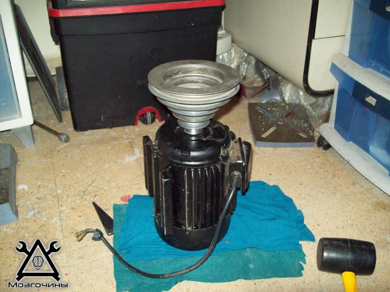
In the process, it was decided not to steam with the old three-phase motor, I still don't have three phases at home, so a new motor per kilowatt of power was obtained and an adapter was machined. The pulley is hoisted to its rightful place on the new engine:
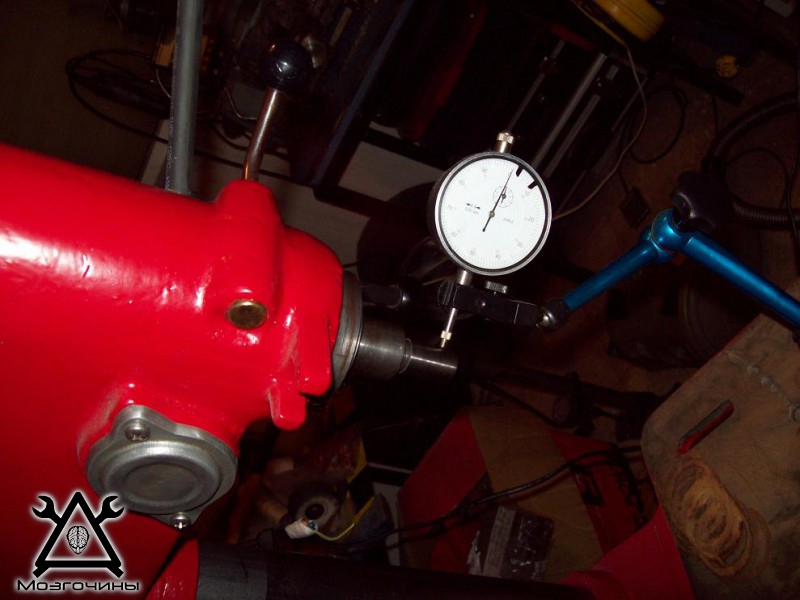
Remembering that it would be nice to check the results of the quill repair, more precisely, the replacement of bearings, and look at the resulting beats, I tried to do it. And - oh, a miracle! - despite the fact that when choosing bearings I did not pursue the accuracy class, the result exceeded all expectations, the radial runout is 0.01:
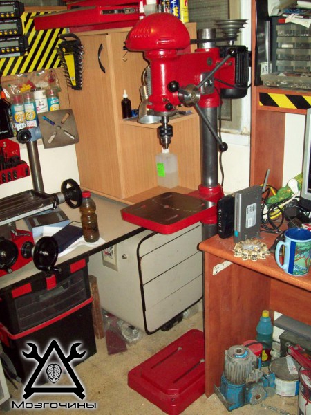
Finally, a couple of last little things - and the machines are already in place:
And at the very end - a little curiosity. The machine came out just shine, accurate, powerful, but one problem: IT SPINS IN THE OTHER WAY, that is, to the left
The moral of the story is, don't drink a lot of beer when you restore equipment. I started it a hundred times, twisted it, twisted it, and NEVER noticed that it rotated in the opposite direction (probably because there was no cartridge, and it was not visible on the round axis). But it doesn't matter. Having rang the engine, I realized that it would not be possible to easily reverse it, and, spitting on it, I bought a set of "left" drills, I have been using it for several years and I am happy as an elephant
- DIY steampunk locket - 12/16/2016
- Steampunk lighter - 08/12/2016
- Another Steampunk flash drive - 07/28/2016
- Steampunk flash drive - 12.07.2016
- Electric reclining scooter - 06/18/2016
- Dashboard for electric scooter - 04.06.2016
- Mini kubotan, opener, keychain - 05/12/2016
- Mini hammer - 04/30/2016
- Flash drive in the form of a spark plug - 04/25/2016
- Pendants for Bikers - video - 04/18/2016
- Electric attachment for a wheelchair - 07/09/2014
- LED headlights for electric bikes - 06/25/2014
- Post-core style lamp - 24.06.2014
- LED headlights for electric bicycles - 06/22/2014
- Marble edging machine - 06/21/2014
Can't you change the direction of rotation? As far as I know, only when connecting the windings with a "delta" with soldered leads is it problematic to change the direction of rotation. In all other cases, you can.
Class. Will there be other articles with restoration?
If I find pictures, there will be another one about a small lathe :)
Looked at the pictures, nope, this is a complete nightmare, nothing is visible, there will be other projects
Not every single-phase device is easily reversible, in mine, without a complete disassembly in order to get to the windings, I simply decided not to steam.
The machine has been operating for 4 years now and there are no complaints, left-hand drills are usually used on CNC machines and therefore of a much higher quality, since they are designed for an intense load.
Of course, a workshop is possible, but besides it there are dozens of articles
You just need to think about which section to put it in.
Let's see, I think it's better as a separate topic, in the toolkit, for example.
Super. Next post post your workshop. Everyone has already appreciated and would like to see your workplace. I think it will be valid.
Your browser doesn’t support canvas.
Universal vertical drilling machines 2H125, 2H135, 2H150 are used at enterprises with single and small-scale production of products and are designed to perform the following operations: drilling, reaming, countersinking, countersinking, reaming and trimming with knives.
The presence of a mechanical spindle feed on machine tools, with manual control of work cycles, allows processing parts in a wide range of sizes from various materials using tools from high-carbon and high-speed steels and hard alloys.
The machines are equipped with a device for reversing the electric motor of the main movement, which allows them to be threaded with machine taps with manual spindle feed.
Placement category 4 in accordance with GOST 15150-69.
Kinematic diagram
The kinematic diagram of the 2H125, 2H135 machines is shown in Fig. 5.
Due to the simplicity of the kinematic schemes, their description is not given.
Note.The table motion chain is the same for all three machines.
The feed chain is the same for the 2125 and 2H135 machines.
Column, table, plate
The column of the machine is a cast iron. The drill head and table are manually moved along the dovetail column guides. The machine table has three T-slots. An electric pump is installed on the foundation slab, and inside the slab there is a reservoir with a sump for coolant.
Gearbox and drive
The gearbox informs the spindle of 12 different speeds of rotation using movable blocks 5 (Fig. 7), 7, 8. The shaft supports of the box are located in two plates - upper 1 and lower 4, fastened together by four ties 6. The gearbox is rotated vertically located by an electric motor through an elastic coupling Yu and a gear transmission 9. The last shaft 2 of the box - the sleeve - has a spline hole through which the rotation is transmitted to the spindle. Through gear pair 3, rotation is transmitted to the feed box. The gear box, like all assembly units of the drilling head, is lubricated from a plunger pump mounted on the lower plate 4. The pump operation is controlled by a special oil indicator on the front of the sub-engine plate.
Mechanism for switching speeds and feeds
Switching speeds is carried out by knob 2 (Fig. 8), which has four positions around the circumference and three along the axis "feed switching is carried out by knob 3, which has three positions around the circumference for machine models 2H125, 2H135 and four for 2H150, and three positions along the axis. The handles are located on the front of the drill head. The counting of the included speeds and feeds is carried out according to tables 1 and 4.
Gearbox
The mechanism is mounted in a separate housing and is installed in the drill head. Due to the movement of two triple gear blocks, nine different feeds are carried out on the 2H125, 2H135 machines and twelve feeds on the 2H150 machine. On 2H125 and 2H135 machines, the feed boxes differ only in the drive, which on the 2H125 machine consists of gears I (Fig. 9), on 2H125, 2H135 machines - of gears 2, 3 - respectively. The feed box is mounted in the bore of the upper support of the feed mechanism worm. On the last shaft of the box, there is a clutch 4, which transfers the rotation to the worm.
Drill head
The drilling head is a box-section cast iron casting, in which all the main assembly units of the machine are mounted: gearbox, gearbox, spindle, feed mechanism, spindle counterweight and gearshift and feed mechanism.
The feed mechanism, consisting of a worm gear, a horizontal shaft with a rack and pinion gear, a dial, a cam and ratchet overrunning clutches, a steering wheel, is an integral part of the drilling head.
The feed mechanism is driven by the feed box and is designed to perform the following operations:
manual approach of the tool to the part; switching on the working feed;
manual feed advance;
turning off the working feed;
manual retraction of the spindle up;
manual feed used when threading.
The principle of operation of the feed mechanism is as follows: when the handwheel 14 (Fig. 10) rotates, the cam clutch 8 turns towards itself, which, through the cage-semi-clutch 7, rotates the pinion shaft 3 of the rack and pinion gear, the spindle is manually fed. When the tool approaches the part, a torque arises on the pinion shaft 3, which cannot be transmitted by the teeth of the cam clutch 8, in the half-clutch cage 7 moves along the shaft until the ends of the cams of parts 7 and 8 come against each other. At this moment, the cam clutch 8 rotates relative to the gear shaft 3 at an angle of 20 °, which is limited by the groove in the part 8 and the pin 10. On the cage - half-clutch 7, there is a double-sided ratchet disc 6, connected to the half-clutch with pawls 13. When moving the cage-half-clutch 7 the teeth of the disc 6 engage with the teeth of the disc 6, made in one piece with the worm wheel 5.As a result, the rotation from the worm is transmitted to the rack gear and the spindle is mechanically fed. With further rotation of the steering wheel 14 with the feed turned on, the dogs 13, sitting in the cage-semi-clutch 7, slip along the teeth of the inner side of the disc 6; there is a manual advance of the mechanical feed.
The feed mechanism allows manual spindle feed. To do this, turn off the mechanical feed with the handwheel 14 and move the cap 9 along the axis of the gear shaft 3 away from you. In this case, the pin 11 transmits the torque from the cam clutch 8 to the horizontal shaft. On the left wall of the drilling head, a dial 4 is mounted for visual reading of the working depth and adjusting the cams.
There is a mechanism for manual movement of the drilling head along the column guides, which consists of a worm pair 2 and a rack and pinion pair 1. To protect the feed mechanism from breakage, there is a safety clutch 15. Nut 16 and screw 17 are used to adjust the spring counterweight.
The spindle (fig. 11) is mounted on two ball bearings. The axial feed force is taken up by the lower thrust bearing, and the tool knockout force is taken up by the upper one. The bearings are located in the sleeve 3, which moves along the axis with the help of a rack and pinion pair. spindle bearings are adjusted with nut 1
A special device on the spindle head is used to knock out the tool. Knockout occurs when the spindle is lifted by the handwheel. The holder of the device abuts against the body of the drill head, and the lever 4, turning around the axis, knocks out the tool.
Electrical diagram
By turning on the Q1 input circuit breaker, voltage is applied to the main and auxiliary circuits, the H2 signal lamp on the control panel lights up. If cooling and lighting is required, then the corresponding switches are placed in the ON position.
By pressing the S2 button RIGHT, the starter coil K1 receives power, the main contacts turn on the M1 motor to the right spindle rotation. Through the K1 auxiliary contacts, the K2 starter is switched on, which turns on the M2 electric motor and the K7 delay relay.
Pressing the S3 LEFT button turns off the K1 starter, the M1 electric motor, the K7 relay. After the discharge of the capacitor SZ, the contacts of the relay K7 (28-26) are closed, and the short circuit starter is switched on in the electric motor M1 for the left rotation of the spindle. Relay K7 turns on again.
With automatic reverse, these switching occurs when the microswitch S6 is triggered from the cam mounted on the dial.
Stop by pressing the S1 STOP button. In this case, the K1 or KZ, K2 starters are turned off, turning off the M1, M2 electric motors. Through the contacts of the K7 relay (7-9), the K6 relay is switched on, followed by the switching on of the K4 and K5 starters. The windings of the motor M1 are connected through the rectifier V1, V2 to the transformer T1. Electrodynamic braking of the spindle occurs.
After the discharge of the capacitors C1, C2, the relay K6 turns off, disconnecting the starters K4, K5.
When changing speeds, if the gears are not engaged, the rotor motion of the motor M1 is applied. Pressing the S4 ROCKING MOTION button activates the K4 starter, supplying a reduced rectified voltage to the IC2-IC3 phases.
Through the resistance R2, relay K6 is switched on with a delay, turning off the K4 starter and turning on the K5 starter. In this case, the undervoltage flows through the phases of ICI-IC2. Such shifts provide rotor rocking, which facilitates gear shifting.
The vertical drilling machine 2n125 is designed for drilling, reaming, countersinking, reaming the holes of parts in a single and small-scale production. Machine accuracy class - N (normal).
The design of the drilling machine is quite rigid and durable, which eliminates the possibility of vibration during processing. It is possible to process parts made of various materials (steel, cast iron, non-ferrous materials), high-speed (P6M5, P18) tools or hard alloy (TK, VK).
Drilling machine device:
- Main drive;
- Machine speed box;
- Plunger pump;
- Plunger pump;
- Machine feed box;
- Column, table, plate;
- Mechanism for controlling rotation speeds and feeds;
- Closet;
- Electrical equipment of the machine;
- Spindle;
- Cooling system of the machine;
- Drilling head of the machine.
3. Cooling switch on;
4.19. Table wedge and drill head adjusting bolts;
5. Handle for moving the table and head;
6.18. Table and head clamp screws;
10. Signal button MACHINE IS ON;
11. Button for turning on the right spindle rotation;
12. Button for turning on the left spindle rotation;
13. Button for turning on the rocking motion of the spindle when switching the speeds of rotation and feed S;
14. Knob for gear shifting;
21. Handle for switching feeds;
22. Button of inclusion of manual feed;
23. Steering wheel of the feed mechanism;
24. Limb for reading the depth of processing;
27. Cooling pump switch;
28. Cam for adjusting the depth of processing;
29. Cam for setting the value of the depth of the cut thread;
30. Lever for automatic reverse of the main drive when the specified value of the depth of the cut thread is reached;
31. Lever to turn off the feed when the specified value of the depth of the hole is reached;
32. Square for manual movement of the head.
Thanks to the mobile units 5, 7, 8, the gearbox receives and transmits to the spindle 12 different speeds of rotation. The shaft supports (bearings) of the gearbox are placed in two plates 1 and 4, which are fastened together by four ties 6. The gearbox rotates from a vertically located electric motor through an elastic overload clutch 10 and a spur gear 9.
Shaft 2 - sleeve - is made with a splined hole, with the help of which rotation is transmitted to the spindle. Through gear pair 3, the torque is transmitted to the gearbox.
The feed box is mounted in a separate cast iron housing and is mounted in the drill head. Movement is carried out using two triple gear sets and receives nine different feeds.
| Video (click to play). |
The feed mechanism is connected to the feed box and is designed to perform various operations, namely:
- manual approach of the cutting tool to the workpiece;
- switching on the working feed of the tool;
- manual feed movement;
- turning off the working feed of the tool;
- manual retraction of the spindle head up;
- manual feed S, used when cutting various threads.

