In detail: DIY monitor LED backlight repair from a real master for my.housecope.com.
Until 2004-2005, CRT monitors and televisions, or, in other words, having a kinescope in their composition were distributed in mass use. They are also, like televisions, called monitors and CRT (cathode ray tube) type monitors. But progress does not stand still, and at one time LCD TVs were released, which included an LCD (liquid crystal) matrix. Such a matrix must be well illuminated by 4 CCFL lamps located on both sides, top and bottom.
This applies to 17 - 19 inch monitors and TVs. Larger TVs and monitors may have six or more lamps. Such lamps in appearance resemble ordinary fluorescent lamps, but, in contrast, are much smaller in size. Of the differences, such lamps will not have 4 contacts, as in fluorescent lamps, but only two, and their operation requires a high voltage - over a kilovolt.
Monitor backlight connector
So, after 5-7 years of operation, these lamps often become unusable, malfunctions are typical for ordinary fluorescent lamps. Here is some additional information. First, reddish tints appear in the image, a slow start, in order for the lamp to light up, it needs to blink several times. In severe cases, the lamp does not light up at all. The question may arise: well, one lamp has gone out, they are standing above and below the matrix, usually two pieces installed parallel to each other, let only three of them burn and the image will only be dimmer. But not everything is so simple.
| Video (click to play). |
The fact is that when one of the lamps goes out, the protection on the PWM controller of the inverter will work, and the backlight, and most often the entire monitor, will be turned off. Therefore, when repairing LCD monitors and televisions, if there is a suspicion of an inverter or lamps, it is necessary to check each of the lamps with a test inverter. I purchased such a test inverter on Aliexpress as in the photo below:
Test inverter with Ali express
This test inverter has a connector for connecting an external power supply, wires with crocodiles at the output, and connectors for connecting plugs, monitor lamps. There is information on the network that such lamps can be checked for operability, using an electronic ballast from energy-saving lamps, with a burned-out lamp spiral, but having working electronics.
Electronic ballast from an energy-saving lamp
What if, using a test inverter or electronic ballast from an energy-saving lamp, you found out that one of the lamps has become unusable and does not light up at all when connected? You can, of course, order lamps on Aliexpress, by the piece, but given that these lamps are very fragile, and knowing the Russian Post, you can easily assume that the lamp will come broken.
Broken Matrix LCD Monitor
You can also remove the lamp from a donor, such as a monitor with a broken matrix. But it is not a fact that such lamps will last a long time, since they have already partially exhausted their resource. But there is another option, a non-standard solution to the problem. You can load one of the outputs from transformers, and there are usually 4 of them, according to the number of lamps on 17 inch monitors, resistive or capacitive load.
Power supply and monitor inverter board
If everything is clear with a resistive one, it can be an ordinary powerful resistor, or several connected in series or in parallel, in order to gain the required rating and power.But this solution has a significant drawback - resistors will generate heat when the monitor is operating, and given that it is usually hot inside the monitor case, additional heating may not please electrolytic capacitors, which, as you know, do not like prolonged overheating and swell.
Swollen capacitors monitor power supply
As a result, if it were, for example, a 400-volt network electrolytic capacitor, that same big barrel known to everyone from the photo, we could get a burnt-out mosfet or a PWM controller microcircuit with a built-in power element. So, there is another way out: to extinguish the required power using a capacitive load, a capacitor 27 - 68 PicoFarad and an operating voltage of 3 Kilovolts.
This solution has some advantages: there is no need to place bulky heating resistors in the case, but it is enough to solder this small capacitor to the contacts of the connector to which the lamp is connected. When choosing the rating of the capacitor, be careful not to solder any ratings, but strictly according to the list at the end of the article, in accordance with the diagonal of your monitor.
We solder the capacitor instead of the backlight lamp
If you solder a smaller capacitor, your monitor will turn off as the inverter will still go into protection due to the fact that the load is small. If you solder a larger capacitor, the inverter will work with overload, which will negatively affect the service life of the mosfets at the output from the PWM controller.
If the mosfets are broken, the backlight, and possibly the entire monitor, will also not be able to turn on, since the inverter will go into protection. One of the signs of overloading the inverter will be extraneous sounds coming from the inverter board, such as hiss. But with the VGA cable disconnected, sometimes a slight hiss coming from the inverter board is normal.
Selection of capacitor ratings for the monitor
The photo above shows imported capacitors, there are also their domestic counterparts, which usually have a slightly larger size. I once soldered ours, domestic at 6 KiloVolts - it all worked. If your radio store does not have capacitors for the required operating voltage, but there are, for example, 2 KiloVolts, you can solder 2 capacitors 2 times larger in series, while their total operating voltage will increase and allow them to be used for our purposes.
Likewise, if you have capacitors 2 times smaller, 3 Kilovolts, but not at the required rating, you can solder them in parallel. Everyone knows that series and parallel connection of capacitors are considered according to the inverse formula of series and parallel connection of resistors.
Parallel connection of capacitors
In other words, when capacitors are connected in parallel, we use the formula for the series connection of resistors or their capacitance is simply added, with a series connection, the total capacitance is calculated using a formula similar to the parallel connection of resistors. Both formulas can be seen in the figure.
DIY monitor repair
Many monitors were already directed in a similar way, the backlight brightness dropped slightly, due to the fact that the second lamp on top or bottom of the monitor or TV matrix still functions and gives, albeit less, but sufficient illumination so that the image remains quite bright.
Condensers in the online store
Such a solution for home use may well suit a novice radio amateur, as a way out of this situation, if the alternative is to repair in a service costing one and a half to two thousand, or buy a new monitor. These capacitors cost only 5-15 rubles per piece in radio stores in your city, and any person who knows how to hold a soldering iron in their hands can perform such repairs. Successful repairs to everyone! Especially for Radioskot.ru - AKV.
In the previous articles devoted to the repair of computer power supplies, we learned how to find and fix simple breakdowns. Let's take a simple look at how switching power supplies differ from conventional transformer ones? The switching power supply unit is capable of delivering significant power to the load with a rather modest size. For this reason, almost all modern technology, with the exception of audio technology (it’s taboo there), is powered by impulses.
Oh yeah, what's all this about? The fact is that a switching power supply is installed in the monitors. And the knowledge that we gained from previous articles on the repair of power supplies is fully applicable to the repair of power supplies for monitors. The difference is purely in the dimensions and layout of radio components.
The giblets of a power supply for a computer look something like this:
And the power supply for the monitor is something like this:
But there is also a significant difference. In power supplies for monitors with LCD backlight, you can see the high-voltage part. He's an inverter. His presence is indicated by inscriptions such as "High Voltage" and terminals for connecting lamps. Please note that the voltage supplied to the lamps is over 1000 volts! Therefore, it is better not to touch and even more so not to lick this part when you turn on the Monica in the network.
By the way, what is the difference between LCD backlit monitors and LED backlit monitors? In LCD monitors, we use fluorescent lamps for backlighting. This is almost the same as fluorescent lamps, just reduced several times.
These lamps are located at the top and bottom of the display and illuminate the image.
If you turn them off, the image will be so dim that you think the display is off altogether. Only a close inspection under lighting can show that there is still an image on the display. This trick will be useful to us to determine lamp malfunctions.
LED monitors use LEDs for backlighting, which are located either on the sides of the display, or behind it.
Now all manufacturers of monitors and TVs have switched to LED backlighting, since it reduces energy consumption by almost half and is much more durable than LCD.
A modern LCD monitor consists of only two boards: a scaler and a power supply
Scaler Is a monitor control board. His brain. Here the monik converts the digital signal into colors on the display, and also contains various settings. It contains the processor, flash-memory, where the monitor's firmware is written, and EEPROM-memory, in which the current settings are saved.
Power Supply, in fact, provides power to the monitor circuit. As I said, it can contain an inverter for monics with LCD backlight. In monitors with LED backlight, there is no inverter.
So, what are the most common monitor breakdowns and what causes them? These are, of course, electrolytic capacitors in the power supply filter.
This is one of the most common LCD monitor breakdowns. Conder can be re-soldered easily and easily. Sometimes the boards do not have a standard capacitor rating, for example 680 or 820 microfarad x 25 volts. If you are faced with swollen capacitors of this denomination and they were not in your radio store, do not rush to go around all the radio stores in your city in search of the exact same denomination. This is exactly the case when "a lot is not harmful." Any electronics engineer will tell you this. Feel free to put 1000 microfarads x 25 volts and everything will work fine. Even more is possible.
Due to the fact that the power supply emits heat during operation, which adversely affects the life of the capacitors, be sure to put capacitors with the designation "105C" on the case. Also, after re-soldering the capacitors, it does not hurt to check the secondary circuit fuse, which is often a simple SMD resistor with zero resistance, frame size 0805, located on the back of the board from the routing side.
And one more nuance, at the output of the power supply, in front of the power connector itself going to the scaler, an SMD zener diode is often placed
If the voltage on it exceeds the nominal, it goes into a short circuit and thereby disconnects our monitor through the protection circuits. You can replace it with any one that is suitable for the voltage rating. Can even be used with pins
After everything is done and repaired, we check with a multimeter the voltage at the power connector, which goes to the scaler. All tensions are signed there. Make sure they match the readings of the multimeter
Problems in the high-voltage part of the power supply (inverter).
If possible, then first of all, always look for the schematics of the device being repaired. Let's take a look at the high voltage part of one of the monitors.
If you see that the monitor power supply fuse is blown, it means that the resistance between the power wires of the monitor cord (input resistance) has become very low at some point (short circuit). Somewhere around 50 ohms or less, which in turn, according to Ohm's law, caused an increase in the current in the circuit. Because of the high current, the fuse wires burned out.
If the fuse is in a metal-glass case, we can insert absolutely any fuse into the mount and ring the resistance between the pins of the plug with a multimeter in 200 Ohm Ohmmeter mode. If our resistance is zero and up to 50 ohms, which is most often the case, then we are looking for a broken radio element that rings to zero or to ground.
Insert the fuse, switch the multimeter to 200 ohms and connect it to the power plug. We make sure that the resistance is very small. Further, we are in no hurry to remove the fuse. So let's see, according to the diagram, which radio components can be short-circuited with us. In the photo, the parts that need to be checked in case of a short circuit in the high-voltage part are highlighted in colored frames
All these procedures for measuring resistance are done in order to call the listed parts one by one. That is, we solder and again measure the resistance through the plug. As soon as we get a high resistance at the input of the plug, replacing the defective radio element, then we can safely plug the plug into the socket.
Monitor backlight disappears
The problem is this: our monitor turns on, it works for 5-10 seconds and goes out. This indicates that one of the display backlight lamps has become unusable. Before that, part of the screen may blink a little. In this case, the inverter will go into protection, which will manifest itself in the automatic shutdown of the monitor backlight.
In order for us to check the lamps and exclude the defective one, we buy a high-voltage capacitor 27 picofarads x 3 kilovolts for 17 "monitors, 47 pF for 19" monitors and 68 pF for 22 "monitors from a radio store.
This capacitor must be soldered to the pins of the connector to which the backlight is connected. The lamp itself, of course, must be turned off. By connecting the capacitor in turn to each connector, we ensure that the inverter stops going into protection.
The monitor will work, although it will be a little dim. This is useful as a temporary solution while the lamp is expected to be delivered, for example from China, or as a permanent solution if it is impossible for one reason or another to replace the backlight.
Of course, rarely does anyone do that. The very trick is to turn off the protection on the PWM chip itself))). To do this, google "remove the protection of the inverter xxxxxxx" Instead of "xxxxxx" we put the brand of our PWM microcircuit. Somehow I turned off the protection on a monitor with a TL494 PWM microcircuit according to the diagram below by soldering a 10 Kiloohm resistor. Monique has been working for the second year now. No complaints).
TVs with liquid crystal LED screens capable of providing crisp images, sophisticated designs and many useful features. In these models, the image is transmitted to the display using LED backlight, evenly spaced across the matrix area.
A chain of LED lamps, consisting of many links, is responsible for the backlight function, therefore, breakdowns of its individual elements often occur. In the event that the backlight fails, LED TV there may be no picture, although there is sound and the device reacts to commands from the remote control: channels are switched, the volume level changes. If you look closely at the display, you can see a dark image and even distinguish the silhouettes of figures, but the damaged backlight makes it impossible to reproduce the picture as expected.
It is quite difficult to identify the cause of the breakdown, since checking all the links in the backlight chain is a long and painstaking work. The technician must measure the voltage at each LED and thus find the damaged one.
There is another way to check LED backlight - supply independent power to each backlight strip, thus finding out the strip on which the faulty LEDs are located, and then separately check each diode on this strip.
If all the elements are in order, then the cause of the breakdown lies in LED driverusually installed on the TV's power supply.
If the image looks distorted or twitches, the cause of the failure is driver malfunction, mechanical damage to the loops, or loss of contact. Also, the image may be distorted with a picture of normal brightness, the appearance of stripes and streaks in certain areas of the screen. It should be noted that the same symptoms occur when the loop contacts are broken, so it is important to correctly identify the problem. If, when you press the screen, the picture is restored or, conversely, new stripes appear, then the problem is in the loop and LED backlight it has nothing to do with it.
LED lights often comes out of standing, even on TVs with LCD screens from leading brands. The main reason for the failure is overpowering: manufacturers by default adjust the image to maximum clarity and brightness in order to increase the product's appeal. Typically, customers use the preset settings and as a result, the current is supplied to LEDs exceeds the permissible level and the elements burn out quickly.
LED driver is a power supply for the backlight. With a constantly increased load, the electrolytic capacitors of the unit break off and the backlight is turned off. The breakage is easy to fix if you replace the part with a more powerful one. There are frequent cases when power surges occur in the power grid. In this case, one of the elements may fail. LED driver:
If one or more elements of the unit fail, the TV screen turns on for a short time and then goes out. In this case, the LED backlight flashes for a few seconds, then the circuit is overloaded and the driver is completely turned off. This happens when overheating: the tightly closed housing of the unit has no ventilation and can malfunction when the temperature rises.
When the driver is overloaded, the overvoltage protection is triggered and the current supply to the backlight circuit is cut off. In this case, an open circuit occurs in the circuit and the backlight goes out.
If an overpowered power supply is supplied to the LEDs, the lamps quickly burn out. In this case, even with the naked eye, you can notice darkening on the back of the chain. The LED driver is responsible for stabilizing the voltage and, when the recommended load is exceeded, interrupts the current supply. With a standard current of 400mA, the load on the LED lamps exceeds the norm and they fail after a short time. To avoid damage, it is necessary to limit the flow of electric current until the moment when the load becomes excessive. With a power of 300 mA, the brightness of the LCD screen will slightly decrease, but the heating temperature of the LED will drop by 35 ° C: from 95 to 60 degrees.
To fix such a breakdown, it is necessary to replace the electrolytic capacitors and make several ventilation holes in the block case.
In order to prevent the problem in advance and increase the life of the TV, it is necessary to reduce the brightness of the screen backlight set by the manufacturer. This will not affect the quality and clarity of the picture, the image will become more natural and easier to understand, and an expensive TV will last much longer.
YouTube channel - Telemaster, groups in VK "Samodelkin" and in Ok "Television workshop«.
Hello Victor, I hope you tell me what to do TV ruby 55 m10, goes into standby mode, you press the power button on the remote control, the red light turns green, it lasts about 5 seconds and it goes into standby mode, it all started with the fact that it turned on for a long time from the beginning, then turned on but the image was narrowed vertically with horizontal stripes from the top and bottom, and then as it warmed up everything became normal, I disassembled it and all the details were intact only 1 of 2 large throttles 2 the throttled which is located in the frame area. it gave, I tried to nail the raster and the TV turned on, I turned it off and returned the raster to its place and it again did not turn on
Hey! Most likely faulty capacitors in the horizontal scan. replace all electrolytes for line and frame power supply.
Hello Victor! Happy New Year to you, Merry Christmas! Such a question: the LG42pc3rv TV turns on normally (with normal brightness), after about 5 minutes of operation, the brightness becomes less and less (the image is barely visible in the dark). Those. the image darkens strongly. Probably the electrolytes in the Led driver can be junk? What do you think? Thanks in advance for your reply.
Hello Victor, haven’t met the lg32lf560v tv, the backlight flew all 18 pieces of lights, from the driver rushing 222v (2 times bust) 3s111 changed, all the voltage also floats on the weekend diodes.
Hello Victor! I need your help from a TV repair specialist, Please tell me how to disassemble the lg49lb620v to replace the LEDs from the front side, or you can remove the trough from the back side by inserting plastic plates where the latches are, what nuances are there how to remove the matrix correctly, I have no experience, so I’m interested, I have already changed it once in the service a year later broke down again. what kind of diodes are these, what is the problem? they did it on purpose so that they burned and drove to their service))).
I took Samsung 6 series and has been working for 3 years.
Thanks for the answer.
Thanks for helping beginners.
You need to remove the matrix to get to the backlight. In most cases, you need to disassemble from the front. To prevent the LEDs from burning out in the future, you need to reduce the backlight current in the TV's power supply. This site has a couple of articles on this matter. You can also go to the channel there is also a video on how to reduce the backlight current.
Thank you Victor for the answer, thank you for reducing the current, tell me how to remove the matrix 49 correctly, do you need suction cups or can you do without them, the matrix will remain on the frame and dismantle it outside the frame on another table. plastic plates in the places of the latches will not damage the matrix in this way.
Thanks again for the answers.
If there are suction cups, it makes the task easier - if you use them correctly. The matrix will have to be removed completely and transferred to another table. you will also have to remove the filters. Do not mix up the order of filters when assembling!
Thank you very much Victor for the information. Tell me, I also called the center there, they told me what to disassemble from the back side, another question about the backlight current sensor is it necessary to add additional resistance to reduce the load on the diodes? Or just removing the backlight by half in the menu will help it?
You can reduce the brightness of the backlight in the menu, it's the same. Only it is necessary to reduce the "BACKLIGHT Brightness"
Thank you for your answers and for your help.
Hello Victor! There is no backlight on Hitachi LED TV! The voltage at the backlight input when turned on is 24 volts. What could be? Thanks!
Or backlight or led driver. Check also the capacitors in the power supply.
Good day. Tell me please. Samsung UE46C5100 TV. there is a duty room when the power is connected. And then, at startup, the clicks of the relyushki begin and that's it. In this case, the voltage across the input capacitors is up to 390v. As I understand it, the PFC works out. What can cause a defense withdrawal. And how to check it. Thanks in advance.
Best regards, Maxim.
Anything can cause protection. check the secondary circuits, the backlight power, the backlight itself, the stabilizers on the lane
Good evening! TV lg43uh603 blue spots appeared on the screen that remain even if the image is made in black and white. What could be? Thanks in advance
Probably, there were blows or pressing on the matrix in these places
You must be logged in to post a comment.
This site uses Akismet to combat spam. Find out how your comment data is processed.
They gave me a 17-inch LG L1753S LCD monitor for spare parts, an old one. Since I really like 4: 3 displays, I just had to resurrect it. These old LCD monitors also have a second advantage - eye-pleasing colors. I turn on the monik in the network, the backlight comes on for 1 second, and goes out. It is clear, then the inverter protection is activated. Disassembling the monitor.
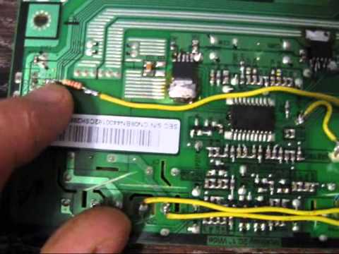
I look, everything seems to be in order with the inverter, but someone pretty much rummaged in the monitor. On the back of the board I see a capacitor soldered instead of one of the lamps, and the wires are cut off from this lamp. I didn't want to bother with the inverter, all the more so to buy lamps, so I decided to disassemble the display module and replace the lamps with LED strips.
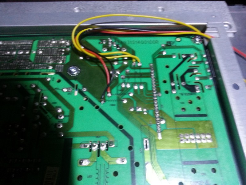
After I disassembled the display module and took out the lamps, it turned out that one of them had burnt out leads, the other was cracked, and the remaining two lamps were intact. We take the lamps out of the “grooves” and throw them away, glue the LED strip into the grooves. It is also imperative to de-energize the inverter, which used to power the lamps. To do this, we are looking for a 12 volt circuit (there are usually a couple of electrolytic capacitors along this circuit), then we track the track that goes in the direction of the inverter microcircuit and cut this track. This action MUST BE DONE.
It is better to take the tape with a neutral-white glow, and also in its width you need to take it as narrow as possible (the width of the tape in the photo is 8 mm). The number of LEDs is also important - at least 120 LEDs per meter of tape.
After the tapes have been glued, we remove the wires and check the operability of the device.
Next, the display module can be assembled. The tapes can be powered from the “12v” circuit, the conclusions are signed on the board.
On the board, you can find jumpers on which there is a 12 volt power supply, and solder the backlight wires to these jumpers.
After this alteration, a problem arises - the backlight is constantly on, and even the brightness is not adjustable. Let's start looking for a backlight brightness control circuit. We carefully look at the inscriptions near the connector. The “ON” pin turns the backlight on and off, when the backlight is on, the “ON” pin has a voltage of about 3 volts. When the backlight is off, there is no voltage at the “ON” pin. The DIM pin adjusts the brightness of the backlight by changing the duty cycle of the PWM signal. When set to almost maximum brightness, the PWM duty cycle is 80.90%, the signal amplitude is 5 volts. When the backlight is off, there is no signal at the “DIM” output either, so there is no need to use the “ON” pin. Both to enable / disable and to adjust the brightness, it is enough to use the “DIM” pin. In order to adjust the brightness, you need to connect the LED strip through the N-channel field, and send a signal from the “DIM” pin to the gate of the field through a small resistor (100.200 ohm).
I took the field worker from a burned-out motherboard, an N-channel AP9T18GH, with a maximum drain-source voltage of 20 volts, and a current of 10 amperes.By the way, each of the segments of the tape consumes about 180 milliamps, so you can use almost any field worker with a current of at least 0.5 amperes. Also, for the sake of interest, I measured the supply voltage along the 12 volt circuit. The voltage was within the normal range.
After the final assembly of the display module, I tested the uniformity of the LED backlight. The result pleased me very much, the uniformity turned out to be decent, only at the very top and at the very bottom, if you look closely, the uneven light from the tape is slightly noticeable. Here is the uniformity of the LED backlight in the photo after the rework:
Average article score: 5 Voted: 11 people.
To add your assembly, registration is required
Service manual: ELENBERG CTV-1515.pdf (32 pages)
If you connected it like this: (1.jpg), then everything should work.
When connected without control, it shines brightly, but. flashes and the TV does not get up in the “duty room” ... ..
Is BIT3193 protection triggered? How to disable protection: (BIT3193 remove protection.jpg).
By the way, what is this 120 ohm resistor? What chain is it in?
At the expense of the driver you are using, just in case, read the messages on 3 pages. from:
speedboy 08/13/2017 10:14
Yuri 08/16/2017 19:43
speedboy 08/22/2017 10:32
2.5-2.8 volts (I believe this is the signal voltage to start the second coil to power the inverter). And from the second connector 12 volts 3 amperes goes to the inverter. As a result, the monitor switching circuit works something like this - when the power is turned on, the main board looks for an input signal at one of the monitor inputs, after detecting it, it sends a signal to the power supply to start the inverter, the inverter, having received power, starts the lamps and sends a signal to the main board through another one connector and only after that, the main board displays the image on the matrix.
That is, the problem is that the switched off inverter does not give a signal to the main board and it does not display the image on the screen, although it does not go to sleep (the indicator shows the monitor's operation, and the microcircuits of the main board are heated during operation). There are five wires from the inverter to the main board, about which I at first thought that this was only a signal about the protection of the inverter and the brightness control, but it turned out that there are one or two more contacts that trigger the image output to the matrix.
If anything, then not a single contact on any board is signed (it is not clear where DIM is, where is ON / OFF, etc.), all the designations of the contacts that go to the inverter from the main board are written as TP271, TP272, TP273, TP274, TP275.
Please excuse me if I wrote the names incorrectly, since I am self-taught, and not a professional radio electronics engineer.
Please also write if you need more photos, or you need to measure the input voltages from the inverter board to the main board when the backlight is turned on.
Many thanks in advance, since there is no other way to restore this rare and wonderful monitor, and there are no alternatives to it in modern monitors, there is only a monitor with the same matrix, which has a worse electronic filling and, like all non-widescreen monitors on The VA matrix is discontinued, this is the Samsung 214T. The PVA matrix is most likely also discontinued as a standard, due to its high cost (IPS in production is, as it were, not cheaper, and the demand for it is colossal), only the cheapest and most primitive VA matrices remained, this is MVA.
I looked with a magnifying glass at five tracks that go from the main board to the inverter connector, it turned out that two of them are connected together right on the main board and minus or ground (GRN) comes to them from the inverter.
I suppose the other three contacts are DIM, ON / OFF, and just the signal contact that informs the main board about the backlight is turned on, then it must be simulated so that the main board without an inverter displays the image on the matrix.
The screenshots are attached to the message above.
I believe that “BRTP” and “BRTC” are brightness (in translation, brightness), that is, adjust the brightness of the lamps, and “DET-INVT” is detect inverter (in translation, detection of the inverter), that is, the contact that you need simulate for the main board to display the image on the matrix.
For some reason, the archive with the StduViewer installer is not added, I will try to attach it to this message, as well as the djvu converted to pdf, even the most compressed one weighs 35 megabytes, so I uploaded it to the Yandex disk, you can download it from the link
P.S.The archives are actually in 7zip, not in plain ZIP, since you can only attach zip archives.
for a second, so I made the wrong conclusion that the image is displayed after the start signal from the inverter. And of course the image without backlighting is practically invisible, to put it mildly. Before that, I saw screenshots with backlight lamps from laptops with a TN matrix. On these screenshots, using a simple flashlight in direct light, a clearly distinguishable monochrome picture was visible. Immediately, practically nothing is visible at all, apparently the antiglare layer makes itself felt, or is it a feature of VA matrices.
5-10 watts). GOLD certified power supply, Sea Sonic Electronics SSP-300TGS Active PFC 300W. Therefore, I need to know what the “PMS” signal does, would it be critical if its absence on the monitor's power supply?
I also did an experiment with “PMS” today. This contact supplies 2.794 volts and only when the monitor is working. If the monitor goes to sleep or is turned off via a button on the front panel, then “PMS” immediately drops to zero. And it also turned out that the first coil produces 5 volts 1.5 amperes, and the second simultaneously outputs 12 volts 1.2 amperes (for powering the main board) and 12 volts 3 amperes (for powering the inverter). That is, with any disconnection or sleep of the monitor, 12 volts disappear from both lines, and 5 volts is supplied all the time while the monitor is plugged into the outlet and the main switch supplies 220 volts to the power supply (apparently 5 volts goes both as power to the main board and at the same time they are needed to wake up the monitor from standby mode).
So, most likely, “PMS” still comes from the main board to the power supply and is needed to run a high-power coil, but I still want to know the expert's opinion, since I judge only by practice and from logical guesses.
And if possible, then I have three more requests to you.
1) You cannot look at the 12 volts circuit that goes from the power supply to the main board, it's okay that 12 volts will be supplied constantly during sleep or when the monitor is turned off through the button on the main panel. As already mentioned above, 5 volts work constantly from the built-in power supply unit, but 12 volts are supplied only during the monitor operation. Just want to be sure 12 volts won't damage the main board while sleeping or turning off the monitor.
2) In addition to the power supply from the system unit, I want to implement LED backlighting with dimmable resistance using variable resistance in order to avoid PWM diodes at low brightness (flickering). I understand that the diodes will heat up more, the efficiency will drop (energy consumption will slightly increase), but eye health is more important. I myself do not know how to correctly calculate what kind of power variable resistor should be put into the circuit. According to the manufacturer, the energy consumption of the tape is 9.6 watts per meter. The tapes are cut with a distance of 5 cm, and my matrix needs two strips of 45 cm each, that is, a total of 90 cm. 10% = 720 milliamps. But it is better to take a resistance with a good power margin, at least 2-3 amperes. I would also like to put an additional ordinary resistance in the circuit, so that at maximum brightness (where the variable resistance supplies power to the line), not 12 volts, but 10.5 - 11 volts, no more went to the diodes. This is necessary so that the diodes do not overheat at maximum brightness, as well as increase their service life, since once again completely disassembling the monitor and the matrix box is still a pleasure.
If it's not difficult, then write the number or model (I do not know how to correctly) of the variable resistance (you need with a handle, like the volume of speakers, since there is a good place in the back of the monitor where it can be brought out) and by how many Ohms (even sooner kOhm) and Watt take a “simple” resistance, which will further reduce the voltage from 12 volts to 10-11 volts.
3) You also need to find a place in the power circuit of the main board, from where you can take 12 volts to power the diode backlight, where the power will be lost when the monitor is turned off from its shutdown and sleep button. I myself can find 12 volts with a tester, which disappear when the monitor is turned off and sleeping, but I'm afraid they suddenly pass through some kind of resistor or transistor, which can burn out from an additional load of 0.7-08 amperes.
For several weeks now I have been assembling the most compact computer with standard components (that is, a standard power supply, a standard motherboard, a processor, RAM, there is even a laptop DVD drive). He brought out the missing "RESET" button, the missing indicators, replaced the terrible blue indication of the computer's operation with a warm orange one, put on the DVD drive switch (so that it would not make noise unnecessarily when turning on the computer) and the amplifier with speakers, and also attached the amplifier itself to the face and volume control. It only remained to wait for the arrival of the anti-dust filters on the case and the power supply unit and a 6-pin connector to remove the speakers from the case and indicate their operation. I plan to screw the speakers to the bottom of the monitor case, and display their operation indication on the bottom of the speaker case (both of them will have the lower plexiglas glowing during operation). I was already glad that there was a little hemorrhoid left before the assembly of this Frankenstein was completed, and then they call me and say that the monitor has stopped working. It was a strong ambush :(
Therefore, I want to do everything as reliably as possible, so that it works for a long time and does not cause more trouble for at least 10 years o_O.
Good afternoon.
This review is addressed primarily to people who know how to hold a soldering iron in their hands and use a multimeter, because without understanding what you are doing and where to connect it, you risk getting a bunch of useless iron.
The parcel arrived quickly (10 days),
Everything is packed perfectly, tapes in a plastic tube and all this is wrapped in several layers of cardboard.
First, we disassemble the monitor, take out the matrix, carefully disassemble it and take out the old lamps.
Do not break the lamps when you take them out, they are gas discharge, that is, they contain mercury.
Installing the tape is extremely simple, you need a thin double-sided tape 4-5mm wide,
I used scotch tape for gluing glasses in mobile phones from a pro store, the thickness of the scotch tape is 0.05mm, the width is from 1mm and more, it is sold in rolls of 50 meters
After installing the tape, we try not to drag dust onto the light distributor when assembling the matrix.
Moving on to the most interesting thing, connecting the inverter.
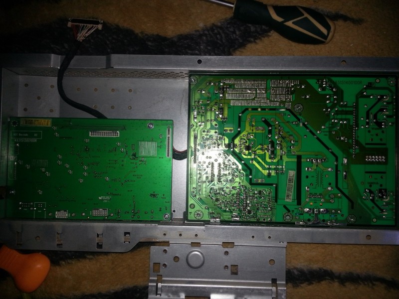
The monitor board looks like this:
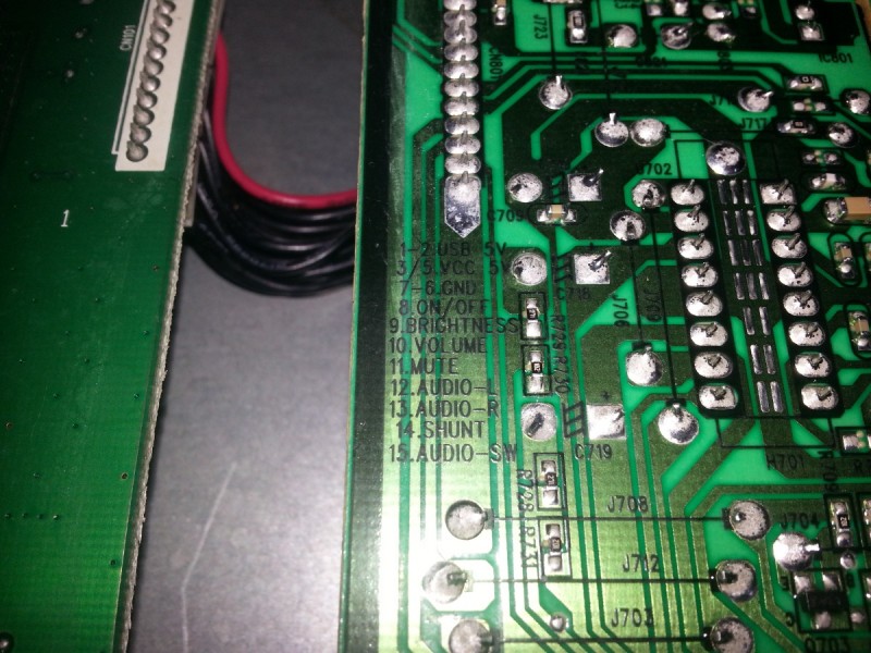
We are interested in the connector that goes from the power supply board (on the right) to the brains of the monitor.
more precisely, not even the connector itself, but the pinout.
Here we are interested in the on / off and brighitness signals, legs 8 and 9, respectively.
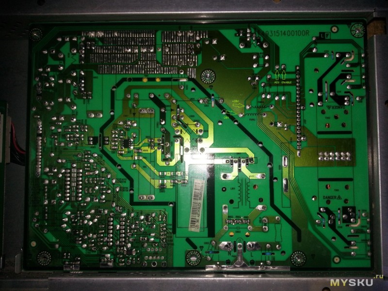
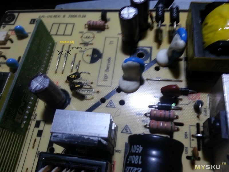
We arm ourselves with a multimeter and find where they come to the control unit for old lamps, at the same time we find a suitable voltage supply next to the inverters, I took the standard power supply of the old inverter.
we unsolder the jumpers from the found places (without unsoldering, my backlight turned on when power was applied to the monitor)
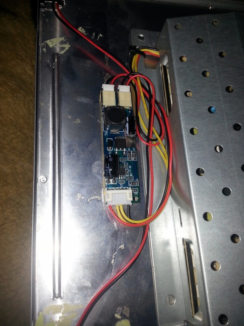
We solder a new inverter to them.
The inverter is mounted on double-sided tape in any convenient place where the wires can reach.
Putting together our new led monitor 🙂
| Video (click to play). |
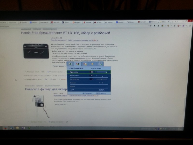
after assembly, the feature of the monitor became clear, the brightness signal is 3.3v and inverse, as a result, the brightness is adjusted from 100 to 0.
it does not bother me at the minimum brightness of the backlight is more than enough

