In detail: do-it-yourself repair of the d 245 engine from a real master for the site my.housecope.com.
When disassembling the diesel engine, remove the pistons and connecting rods only upwards. Remove carbon deposits from the top of the cylinder liner before removing the pistons.
When replacing parts of the sleeve-piston group and the crank mechanism, pay attention to the size groups of the parts.
The cylinder liners by the inner diameter and the pistons by the outer diameter of the skirt are sorted into three size groups in accordance with Table 6. The designation of groups (B, C, M) is applied on the liner lead-in cone and on the piston crown.
110
110
110
In a set for one diesel engine, select pistons, connecting rods and piston pins of the same weight group, the weights of the connecting rods complete with pistons should not exceed 30 g.
Main and connecting rod journals and crankshaft bearing shells are manufactured in two nominal sizes in accordance with table 7.
75,25
68,25
75,00
68,00
Crankshafts, the connecting rod and main journals of which are made according to the size of the second nominal, have an additional designation on the first cheek:
- “2K” - main journals of the second denomination;
- “2SH” - connecting rod journals of the second denomination;
- “2KSH” - connecting rod and main journals of the second denomination.
On each piston of the D-243 diesel engine, in accordance with Figure 33a, an upper compression ring is installed, coated on the outer surface with chrome, two compression conical rings and one oil scraper ring of a box-type with a spring expander, on the D-245 diesel engine - three rings (Figure 33b). The compression tapered rings on the end surface of the lock are marked “top” (“TOP”), which, when installing the rings, must face the piston crown. The oil scraper ring expander joint must not line up with the ring joint.
| Video (click to play). |
Place the piston ring locks at an even distance around the circumference.
Install the distribution gears according to the marks on them in accordance with Figure 34. The marks on the intermediate gear must align with the corresponding marks on the crankshaft and camshaft gears and the fuel pump drive gear.
When assembling the air cleaner after washing it with the recess of the filter elements, install them in the housing in the following sequence: first - the filter element with the smallest diameter (0.2 mm) of the nylon thread; the second is a filter element with an average diameter (0.24 mm) of a nylon thread; the last filter element with the largest diameter (0.4 mm) nylon thread.
a) Piston of diesel D-243 b) Piston of diesel D-245 1- upper compression ring; 2 - compression tapered ring;
3 - oil scraper ring
... Figure 33 - Piston ring installation diagram.
1 - camshaft gear; 2 - intermediate gear; 3 - crankshaft gear; 4 - gear wheel of the fuel pump drive.
Figure 34 - Scheme of installation of distribution gears.
Description of the consequences of failures and damages
Instructions for determining the consequences of failures and damage to an assembly unit
Instructions for eliminating the consequences of failures and damage
1.Leak of coolant through the drain
1.1 Wear of the contact surfaces of the mechanical seal
1.2 Wear of the bearing assembly
1.1 Check the coolant level in the cooling system during ETO
1.1.1 Inspect the water pump on a running diesel after starting during the warm-up period
1.2 By applying force to the pump pulley with the diesel engine off, check the radial play in the bearing assembly
Remove the water pump from the diesel,
Replace the water pump oil seal
Replace bearings, water pump housing (if necessary)
2.Pump vibration, increased noise
2.1 Wear of the bearing assembly
idle diesel check the radial play
Remove the water pump from the diesel engine, disassemble the water pump (section 4.3)
Replace bearings, water pump housing (if necessary)
3.There is no circulation of coolant in the diesel cooling system
Turning the impeller on the pump shaft
When monitoring the temperature of the diesel engine cooling system according to the temperature indicator, a sharp increase in the temperature of the coolant is observed
Remove the water pump from the diesel,
Replace the impeller and / or pump shaft
4.2.3.1 Dismantling the water pump.
Unscrew the nut 9 (Figure 35) securing the water pump drive pulley.
Using a puller, remove the pulley 7 of the water pump. Remove the ring 12 from the pump casing, which retains the bearing assembly. Remove the impeller 3 from the pump shaft 2 using the threaded hole in the end of the impeller (M18 × 1.5) using a special bolt.
Press the shaft with bearings out of the water pump housing. The direction of pressing is in the direction of the pulley installation. Press the bearings off the shaft. Remove the thrust ring 13.
Press the oil seal out of the pump housing.
1 - case; 2 - pump roller; 3 - impeller; 4 - seal of the water pump SP / 1341; 5 - bearing; 6 - bushing; 7 - pulley; 8 - key; 9 - nut; 10 - plug; 11 - washer; 12 - retaining ring; 13 - persistent ring.
Figure 35 - Water pump
4.2.3.2 Assembling the water pump for diesel engines D-243 and D-245
Install the thrust ring 13 on the pump shaft, press on the bearings. Fill the bearings and the bearing cavity with Litol 24-MLi 4 / 12-3 grease in the amount of 45 g. Press the shaft with bearings into the pump housing. Install the ring 12 retaining the bearing assembly.
Install the pump pulley, washer and nut. Tighten the nut, providing a torque value of 120 ... 140N · m.
Press the water pump seal 4 with the inner casing onto the water pump shaft through a mandrel (Figure 36) and, at the same time, press the outer seal casing into the water pump casing until the seal casing flange stops against the seating surface of the pump casing, while the design of the mandrel must ensure that the inner casing is pressed on seals in such a way that the end surface of the inner casing is located at a distance of 11.2 ± 0.2 mm from the mating surface of the pump casing.
Figure 36 - Driver for pressing the water pump seal (Main dimensions)
Press the impeller onto the shaft, install the plug into the end of the impeller. The sinking of the impeller end relative to the mating plane of the pump casing should not exceed 0.3 mm, the impeller protrusion is not allowed.
Install the water pump on the diesel.
To ensure the operability of diesel engines, save material and money for their repair and preparation for work, it is necessary to strictly observe the rules for storing diesel engines outside working hours.
Storage of diesel engines regardless of the season should be carried out in full compliance with GOST 7751-85. For long-term storage, the tractor (machine) with a diesel engine installed on it must be placed in a closed room or under a shed.
The preparation of the diesel engine for storage must be completed no later than 10 days from the date of completion of the work.
When preparing a diesel engine for long-term storage, perform the following work:
- clean the diesel from dust and dirt;
- drain the coolant from the cooling system;
- drain the oil from the diesel engine crankcase, the fuel pump housing and the gearbox housing of the starting engine, clean the rotor of the centrifugal oil filter;
- pour conservation oil K-17 GOST 10877-76 or fresh dehydrated oil with 5% AKOR-1 additive GOST 15171-70 into the diesel crankcase, the fuel pump housing and the gearbox housing of the starting engine;
- change the oil in the sump of the air cleaner;
start the starting engine and, without turning on the fuel supply, turn the diesel engine until oil pressure appears in the lubrication system;
- turn off the starting engine, unscrew the spark plug and pour 40 g of K-17 conservation oil or dehydrated motor oil with AKOR-1 additive into the hole, turn the starting engine shaft by short-term (1-2 s) turning the starter on and off for several turns, screw the spark plug or close the hole with a wooden stopper.
Rotate the diesel engine with electric starter without fuel supply by short-term (no more than 15 s) turning on the starter until oil pressure appears in the lubrication system.
Drain the storage oil from the diesel crankcase, fuel pump and starting engine gearbox.
Drain sediment from the coarse and fine fuel filter, loosen the fan belt tension.
Seal the outer openings of the muffler (exhaust manifold), dry filter, breather, thermostat housing (if the diesel engine is not installed on the tractor, machine) with covers made of polyethylene film or waxed paper.
During storage, turn the diesel engine crankshaft several revolutions at least once a month.
Diesels removed from tractors (machines) or received as spare parts should be stored mothballed in a closed room on special stands. It is forbidden to store batteries, acids, salts, alkalis and other substances that can cause corrosion of metals in the same room with diesel engines and spare parts.
When storing the tractor (machine) in an open area or under a shed for a short time, perform the following operations:
- clean the diesel from dust and dirt;
- wrap the exhaust pipe and the dry filter of the air cleaner with wax paper or plastic wrap.
Before starting the tractor (machine) into operation, carry out all preparatory work in accordance with the instructions in section 2.1.
Installing cylinder liners
The cylinder liners and cylinder block seating surfaces for liners should be wiped with a napkin and blown out with compressed air.
Install the cylinder liners in the diesel block. The protrusion of the collars of the cylinder liners above the plane of the block when pressing the liner with a force of 9 ± 0.1 kN should be 0.05 ... .0.11 mm. For details on installing the liners, see the article - Cylinder liners D-245 installation
Crankshaft stowage
Before assembly, each crankshaft must be checked on a magnetic or ultrasonic flaw detector for micro and macro cracks, as well as for the correspondence of the selected set of main bearing shells to the size of the main journals. We look at the article in detail - D-245 crankshaft laying
Installing the connecting rod-piston group
Check the consistency of the piston kit size group and the cylinder liner size group.
Pistons of the same set on a diesel engine must be of the same size group, corresponding to the size group of cylinder liners.
Installation of the gas distribution mechanism
The distribution board gasket must not be visibly damaged.
Nuts and other mechanical damage to the processed surfaces of the distribution board are not allowed.
Installing the cylinder head and valve train
We look at the installation of the cylinder head in the article - Cylinder head installation D-245
Installation of high-pressure fuel pumps, injectors, high and low pressure pipes
The filling plate of the high pressure fuel pump must be clean; nicks and other damage to the slab are not allowed. The fuel pump gasket must not be visibly damaged.
When installing the fuel pump, it is necessary to match the marks of the gear wheel of the fuel pump drive and the splined flange.
The spline flange of the fuel pump gear must freely, without jamming, find on the splines of the fuel pump shaft sleeve.
The fastening bolts of the fuel pump gear wheel flange must be tightened to a torque of 18. 25 Nm.
The injectors of the same group must be installed on the diesel engine. The gaskets on the side adjacent to the injectors must be lubricated with grease. The fastening bolts of the injectors must be tightened to a torque of 20. 25 Nm. The high-pressure pipes must be fixed at a distance of 10.15 mm from the union nuts with clamps with gaskets.
Before installing on a diesel engine, the low pressure fuel pipes should be blown out with compressed air.
Installing the oil pump and power steering pump housing
Before installing the oil pump, check the ease of rotation of the gears. The guide pins of the oil pump must fit snugly into the holes in the first main bearing cap. Lock washers must be placed under the bolts of the oil pump. The lateral clearance between the teeth of the oil pump drive gears should be within 0.1. 0.65 mm. The bolts securing the outlet pipe to the oil pump and the cylinder block must be tightened to a torque of 15. 25Nm. Before installation, the power steering pump housing must be flushed and blown out with compressed air. The lateral clearance between the teeth of the gear wheels of the drive of the hydraulic pumps should be within 0.08..0.2 mm. The housing of the drive, hydraulic pump after installation on a diesel engine must be closed with a cover with a gasket. The oil pump supplied to the assembly of the diesel engine must be run in and tested. We look in detail at the article - Installing the oil pump and the pump housing of the D-245 power steering
Installing the oil receiver
Before installation, the oil receiver must withstand a hydraulic test with diesel fuel or an air test under a pressure of 0.1 ± 0.02 MPa. Leakage, leakage or leakage of air at the junction of the branch pipe and the flange is not allowed. Beads and irregularities after welding must be smoothed out.
Installing the oil sump
Seals must be installed in the grooves of the oil sump support prior to assembly.
Before installing the oil sump, trim the protruding ends of the gasket between the distribution cover and the plane of the block. The plane of contact of the oil sump to the block before installing the gasket must be lubricated in three places with UZOM paste GOST 13489-79. No nicks or dents with a width of more than 0.1 mm on the machined surfaces of the oil sump are not allowed.
Installing the back sheet, cuff housing and crankshaft flywheel
The back sheet should sit tightly on the pins pressed into the cylinder block. The back sheet and the plane of interface with the crankcase, as well as the surface of the flywheel and the crankshaft flange must be wiped with a clean cloth. The paronite gaskets of the back sheet and the cuff body must be lubricated with UZOM paste on both sides before installing on the pins. The mating surfaces of the flywheel and crankshaft flange must be free of nicks, burrs, or other damage.
The flywheel mounting bolts should be tightened evenly in several steps. The final tightening of the flywheel mounting bolts should be carried out to 180.200 Nm.
Installing the diesel engine support and the crankshaft pulley
The crankshaft pulley must be wiped with a clean cloth. There must be no nicks or burrs on the seating and working surfaces of the crankshaft support and pulley. The crankshaft pulley mounting bolt must be tightened with a torque of 240.280 Nm.
Installing a centrifugal oil filter (centrifuge)
How to disassemble the engine MMZ D-245.
Engine repair. MMZ D-245. Repair engine. MMZ D-245
Overhaul of D 245 E2 Part One
MMZ D245.7E2 engine with compressor and generator (GAZ 3308, 3309 with pneumatic brakes)
WHY THE GASKET D 245 FREQUENTLY BURNS OUT
This is how the crankshaft of the MMZ D-245 diesel engine should rotate, if the geometry is normal
Oil pressure D 245 dropped sharply
repair Valday. we get to the engine, without removing from the car.
Assembling the D 245 engine Completion Installation of ignition
Repair of the D245 (MTZ 1025) engine
Repair of the D-245 engine Installing rings on pistons, Installing ShPG in the engine block How to put PTFE rings on the cylinder head gasket
Overhaul D 245 E2 Part One. I start to repair the engine (to assembly) Laying of liners, installation of the crankshaft, flywheel, clutch, etc. I decided to hang it on the engine to the maximum, even adjust the ignition (although about the ignition in my opinion in the next part)
do not copy. do it your way.
–
In this video, I will tell you an interesting case during the operation of the D-245 E2 engine associated with a sharp drop in oil pressure, the reason turned out to be very unusual. Thanks for watching! Join the group - Club of five-ton drivers - # lost # pressure # mtz # bypass # valve # zubrenok # grease # no # lit # increase # knock # plate # oil # filter # falls # low # oil # start # engine # zil # raise # consequences # q # 12 # 245 # 5301 #pressure #dimension #oil #food #tv #genre # q245
Valdai repair, knocking on the 1-2 cylinder engine.
How to set the ignition on the D-245 E2 engine, finishing the assembly of the engine # long range # truck # maz # zubrenok # gennadich # adjust # ignition # installation # fuel pump # engine # correct # set # angle # adjustment # MTZ # repair # timing # moment # injection # nozzle # DIY # fuel # equipment # turbine # earlier # later # trucking # travel # advancing # tags # 4370 #live # d245 # e2
Initially, the D 245 series engine was made in the 7E2 modification, which had increased dimensions and a mass of about 700 kilograms. This powertrain was actually a modernized version of the outdated 240 series. It complied with the Euro 2 environmental standard and was completely discontinued in the mid-nineties. In the mid-nineties, the D 245 engine underwent significant changes. The power system was completely changed, direct nozzles appeared, and the engine itself began to comply with Euro 3 environmental standards.
Useful DIY Tips
DIY d 245 engine repair
Photo for the announcement: turbine TKR 6 at MTZ and Bychok engine D-240 - Agro-Ukraine
Turbine repair do it yourself photo
Is it worth repairing a turbine with your own hands? at Bumpershop.RU
I sell zil - Zil, 1993 - Trucks in Biysk
Installing the D-240 engine on a ZIL or GAZ car> - Farmer.Ru - The main farm portal - all about business in rural areas
Turbine tkr6.5.1-03.05. Price, Photo
Engine D-245.7E2-1807 GAZ-33104 Valdai, 122hp. EURO-2 analogue of D-245.7E2-254 D-245.7E2-1807
Do-it-yourself gas turbine repair 3309
DIY d 245 engine repair Tips for motorists
Selling engine GAZ GAZ, D245 - Sale of auto parts in Tomsk
Engine overhaul d 245 video - Multi registration
245 engine with turbine price
DIY d 245 engine repair
Trucks for sale - ZIL 4331, 1994 - Trucks in Tula
I sell zil - Zil, 1993 - Trucks in Biysk
Selling an engine. MTZ D 245. Turbo. - Zil, 2013 - Trucks in Chita
Do-it-yourself refurbishment of a zil to a diesel photo
Zil car. Price on request. Buy in Omsk region
To dismantle the power unit, it is recommended to install the bus on an inspection pit, above which there is a lifting device. The assembled mass of the power unit without refueling with fuel and oil is 600 kg, therefore, to dismantle it, you must have a lifting device with a lifting capacity of at least 1 ton; the height to the hook must be at least 2 m.
Dismantling a diesel engine from a car or bus using a lifting device is shown in Fig. 1 Before dismantling the power unit from a car or bus, it is necessary to drain the coolant from the cooling system, as well as drain the oil from the diesel crankcase and gearbox. The coolant is drained off through two drain taps. When disassembling small parts, it is recommended to put them in a separate container, and when disconnecting wires from electrical devices, set the screws and nuts in their original position and screw them on by hand.
Before dismantling the power unit, the following preparatory work must be performed:
- remove the hatch cover of the battery socket and disconnect the wires from the positive pole of the battery, remove the starter wire, turn off the ground with the switch;
- raise the hood of a car or a bus and disconnect the wires from the devices and adapter blocks by loosening the screws of the clamping clamps, disconnect the hoses of the liquid and oil radiators and the pipe with hoses going to the heater;
- disconnect the shutter drive cable (if any) and remove it together with the casing from the hole in the front wall of the cab;
Rice. one. Dismantling a diesel engine from a car or bus using a lifting device
- unscrew the nuts securing the radiator and dismantle it manually or using the KZ-0355 tool (Fig. 2);
- remove the rubber cushions with a spacer sleeve;
- disconnect the drive of the high pressure fuel pump (injection pump), remove the foot drive rod, the manual drive cable for turning off the fuel supply;
- disconnect and remove the tubes: compressed air outlet from the compressor, pressure regulator, supplying fuel to the fuel pump;
- disconnect the high and low pressure hoses from the power steering pump housing;
- remove the steering propeller shaft;
- disconnect the exhaust pipe from the exhaust pipe by unscrewing the nuts;
- disconnect the pipeline from the air filter to the turbocharger;
remove the hatch cover of the cab floor by unscrewing the mounting bolts; remove the gear lever housing with the gasket assembly with the lever by unscrewing the crankcase mounting bolts. Close the hole for the gearbox housing with a cardboard cover, attaching it with two bolts;
Rice. 2. Dismantling the radiator using the KZ-0355 tool
- disconnect the speedometer drive by unscrewing the union clamping nut and the tachometer drive;
- disconnect the pedal drive of the service brake system by disconnecting the rod and the pedal lever;
- disconnect the propeller shaft from the gearbox flange by unscrewing the fastening nuts;
- disconnect the clutch release drive by disconnecting the pipelines on the pneumohydraulic booster (PGU), after draining the fluid from the drive;
- unscrew the fastening bolts of the front support and two rear supports of the diesel engine. Disconnect the brake pipes from the parking brake valve (when installing the parking brake actuator from the brake brake system).
Unfasten bolts for bumper and front frame cross member and remove from vehicle or bus.
Carefully lifting the power unit by the eyebolts with a lifting device (see Fig. 1), dismantle it from the frame of the car or bus under the engine cross member, unscrew the bolts of its fastening, and, bringing the power unit forward, remove it from the car or bus. Then install the power unit on a special trolley for transportation to the place of disassembly.
Before disassembly, the diesel engine must be cleaned of dirt and oil, rinsed with kerosene or a degreasing solution.
For washing, it is recommended to use washing solutions MS-6 or MS-8 TU 6-15-978-76 with a concentration of 20.30 g / l at a temperature of 90.100 ° C. Then blow out the diesel engine with compressed air. Removal of devices and assemblies from the diesel engine is recommended to be carried out on a stationary rotary stand mod. OPR-989. The gearbox must be removed from the diesel before installing the diesel on the stand. The rotation of the diesel engine around the horizontal axis of the stand is carried out using a worm gear located on the stand. When disassembling or assembling, the diesel must be fixed in any position when braking the worm gear. In the process of disassembling the diesel engine, all parts suitable for further operation should be protected from damage.
Parts and normals removed from the diesel engine should be placed in a specially prepared container, in which they are transported to the operations of washing, checking and troubleshooting.
Most of the diesel parts are interchangeable, but some require an individual fit with the mating part.
When dismantling the gearbox, you must:
unscrew the gearbox mounting nuts with a spanner;
- disconnect the CCGT rod by removing the finger from the clutch fork lever;
disconnect the box from the clutch housing using a mounting blade and, shaking it, remove it with a hoist or using a hydraulic jack. In this case, pay attention to the position of the clutch release fork.
To dismantle the clutch housing, you need to remove the clutch housing cover, unscrew the bolts securing the crankcase to the back sheet and remove it from the dowel pins.To dismantle the clutch, unscrew the clutch cover mounting bolts with a socket wrench, remove the pressure plate assembly with the cover and the clutch release lever, remove the driven disc assembly.
When removing the oil filter, you must:
- unscrew the bolts securing the filter housing;
- remove the filter from the diesel engine together with the sealing gasket,
When dismantling the starter, it is required to: unscrew the bolts and nuts securing the starter to the clutch housing;
remove the starter from the housing,
To remove the generator you should:
- unscrew the tensioning bar fastening bolt;
- unscrew the nuts securing the generator to the bracket;
- remove the generator and the alternator drive belts by freeing the alternator pulley from the drive belts. After that, remove the alternator brackets from the diesel engine by unscrewing their fastening bolts.
When dismantling the fan and liquid pump, the following work must be performed:
- unscrew the bolts securing the fan to the pulley;
- unscrew the bolts securing the liquid pump housing to the end of the block;
- remove the pump with gaskets.
The diesel engine is disassembled in the following sequence.
From the diesel engine installed on the stand with the pallet downwards, it is necessary to remove the thermostat with the branch pipe, the housing of the liquid pump and the fan assembly.
Then, unscrewing the nuts securing the exhaust manifold, remove it.
Using a set of inertial universal puller, dismantle the injectors from the diesel engine (Fig. 1).
Remove the cap and cover from the valve mechanism, the oil supply pipe to the rocker arm shaft.
Remove the axle struts assembled with the rocker arm shaft and the rocker arms themselves and remove the rods from the cylinder block.
Remove the cylinder head bolts, remove the cylinder head and gasket.
Unscrew the bolt securing the pulley for the drive of the liquid pump and the fan from the end of the crankshaft, remove the front support of the diesel engine, and then the pulley using a special puller (Fig. 2).
Remove the camshaft cover, idler gear and unscrew the two bolts securing the thrust flange, and then, turning the camshaft, remove it from the cylinder block.
Remove the camshaft drive gear using a press and a mandrel, having previously unscrewed the gear mounting bolt (Fig. 3).
Remove the flywheel, seal housing with rubber collar, slinger washer and diesel back plate.
Turn the diesel engine 90 and remove the oil sump and connecting rod caps with inserts; remove the connecting rods with pistons from the cylinders and put the connecting rod caps in place.
When disassembling the diesel engine, the pistons and connecting rods must be removed only upward (Fig. 4). Before removing the pistons, the carbon deposits must be removed from the top of the cylinder liner.
When replacing parts of the piston sleeve group and the crank mechanism, special attention should be paid to the size groups of the parts.
Unscrew the nuts securing the main bearing caps and remove them together with the shells.
Remove the crankshaft and take out the tappets.
Dismantling gears from the crankshaft can be done using a universal puller 1P-21305 (Fig. 5).
Remove the compression and oil scraper rings from the pistons using the I804.03.000 tool (Fig. 6).
Remove the circlip from the piston pin bosses using round nose pliers (Fig. 7); press out piston pins
Press out the cylinder liners from the block using the I804.01.000 tool (Fig. 8).
After disassembly, all parts of the diesel engine must be rinsed and blown with compressed air. For washing it is necessary to use washing solutions MS-6 or MS-8 TU 6-15-978-76 with a concentration of 20-30 g / l at a temperature of 90-100 °.
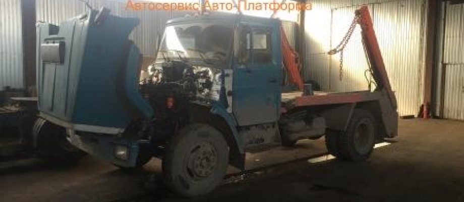
The types of work that we perform on D240 / D245 engines in the AutoPlatform Lyubertsy truck service station:
- dismantling and overhauling the engine (overhaul) - the price is 45,000 rubles.
- replacement of the cylinder head gasket - price from 8000 rubles.
- valve adjustment - the price is 1500 rubles.
- replacement of O-rings on cylinder liners - the price without removing the engine is 20,000 rubles.
- removal and installation of the turbine - the price is 2500 rubles.
- removal and installation of injection pump - the price is 2500 rubles.
- removal and installation of nozzles - the price is 500 rubles / 1 piece.
- adjustment of the ignition system - the price is 1000 rubles.
- restoration or replacement of the block and cylinder head;
- repair, boring and grinding of crankshafts;
- flushing units and parts;
- assembling and starting the engine;
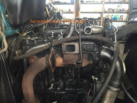
- Punches the cylinder head gasket (cylinder head)
- Liners in the cylinder block are sinking;
- Incorrect operation of injection injectors;
- Wear of the crankshaft liners;
- Malfunction in the ignition system;
- Failure of the turbine;
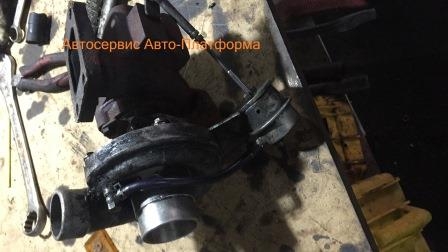
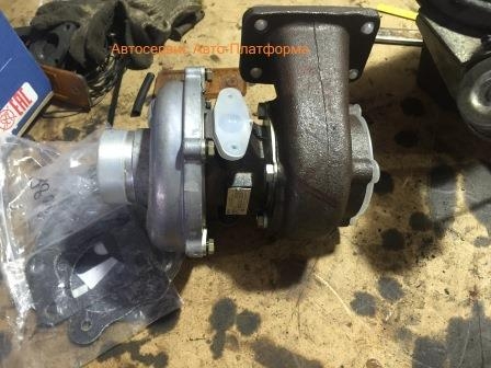
Apply to engine repair in a truck with a D240 / D245 engine necessary for:
- the ingress of coolant into the engine lubrication system or vice versa;
- increased duration of starting by the starter (should not exceed twenty seconds)
- the appearance of interruptions, instability under certain operating conditions of the engine;
- the occurrence of knocking, smoke release;
- increased fuel consumption;
- an increase in the temperature of the liquid for cooling (above 95 degrees);
- increased gas consumption from the breather;
- increased oil consumption for waste;
- the occurrence of leaks of technical fluids.
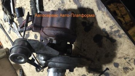
Types of work on the repair of D240 / D245 engines "Auto platform" car service carries out maintenance and repair of diesel engines D240 / D245 of trucks Zil, Maz, MTZ, Voldai, Gaz, Paz. We have a complex of modern professional equipment. Our specialists carry out diagnostics and engine repair in Lyubertsy at a high level.
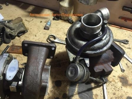
For the smooth operation of diesel engines D240 / D245, our experts recommend that you undergo regular maintenance of the ZIL car and follow the recommendations for operation and technical requirements of the manufacturer. The frequency of service maintenance depends on the operating conditions, loads and the condition of the road surface.
Trucks of the ZIL brand are distinguished by a rather long service life. These vehicles are widely demanded in construction and industrial works. A high load can lead to premature wear of major assemblies and parts. Therefore, it is necessary to regularly diagnose the condition of the car. To carry out such work, you can contact the Auto Platform car service, which, among other things, carries out engine repair D240 / D245
Timely diagnostics will allow you to operate the engine at full power, without visible interruptions in operation.
- Posts: 32
- Location: Novosibirsk
September 22, 2013, 14:42 # 238
Please tell me d-245-12s smokes blue and stinks as many tears are flowing what needs to be twisted?
- Posts: 2855
- Location: VORONEZHgrad
September 22, 2013, 14:54 # 239 + 1
lexx 54 rus, September 22, 2013, 14:42, # 238
Please tell me d-245-12s smokes blue and stinks as many tears are flowing what needs to be twisted?
set the injection correctly and accurately and check, along the way, the forces for spray, and the internal combustion engine for compression.
- Posts: 32
- Location: Novosibirsk
September 22, 2013, 15:02 # 240
GENACL, 22 September 2013, 14:54, # 239
set the injection correctly and accurately and check, along the way, the forces for spray, and the internal combustion engine for compression.
Internal combustion engine and injection pump from repair compression 27 + - 0.5 and where to turn the injection?
- Posts: 2855
- Location: VORONEZHgrad
September 22, 2013, 15:04 # 241
in general, a new or beautifully otkapitalny internal combustion engine should have a compression of 35 bar. and Usually blue smoke occurs with late injection.
- Posts: 32
- Location: Novosibirsk
September 22, 2013, 15:12 # 242
I put everything new and did not measure the compression right after the repair, including the head. He measured it when he passed about 3 tons. There was no running-in either. Maybe that's why it is less. Thanks for the advice, I'll go twirl
- Posts: 339
- Location: Chelyabinsk region Kizilskoe
September 22, 2013, 23:11 # 243
savely77, 22 September 2013, 11:58, # 232
Help me out, I did the repairs myself, d 245, it starts up fine, it works steadily, I haven't tried it. The problem is in the sound. The metal sonorous rattles so hard, the ears are jammed. With the increase in revolutions, the sound intensifies. And now what was done.In the block, a seat was drilled for the liners, the liner was shifted and pierced the gasket 5 raaaaaaz. The specialist said that he removed the plane of the block to the depth of the groove. The head was planned 2 times. The gasket was one usual, there was nothing under the liners. The question is, can the piston reach the head to the valves. ? Or even the marks on the gears, but I'm sure on 999999999999 that everything is ok. Valve adjustment? The injection spun right to left, the sound is present.
He machined the block, lowered the sleeves lower, and the connecting rods did not become shorter, perhaps the pistons reach the head. For such a repair, there are still steel gaskets for a conventional gasket, or two simple ones are put, and the engine resource
Before disassembly, the diesel engine must be cleaned of dirt and oil, rinsed with kerosene or a degreasing solution. For washing it is recommended to use washing solutions MC6 or MC-8 TU 6-15-978-76 with a concentration of 20-30 g / l at a temperature of 90.100 ° C. Then blow out the diesel engine with compressed air.
Removal of devices and units from a diesel engine is recommended to be carried out on a stationary rotary stand mod. OPR-989. The gearbox must be removed from the diesel before installing the diesel on the stand. The rotation of the diesel engine around the horizontal axis of the stand is carried out using a worm gear located on the stand. When disassembling or assembling, the diesel must be fixed in any position when braking the worm gear. In the process of disassembling the diesel engine, all parts suitable for further operation should be protected from damage.
Parts and normals removed from the diesel engine should be placed in a specially prepared container, in which they are transported to the operations of washing, checking and troubleshooting.
Most diesel parts are interchangeable, but some require individual adjustment with the mating part
The diesel engine is disassembled in the following sequence.
From the diesel engine installed on the stand with the pallet downwards, it is necessary to remove the thermostat with the branch pipe, the housing of the liquid pump and the fan assembly.
Then, unscrewing the nuts securing the exhaust manifold, remove it.
Using a set of inertial universal puller, dismantle the injectors from the diesel engine (Fig. 1).
Remove the cap and cover from the valve mechanism, the oil supply pipe to the rocker arm shaft.
Remove the axle struts assembled with the rocker arm shaft and the rocker arms themselves and remove the rods from the cylinder block.
Remove the cylinder head bolts, remove the cylinder head and gasket.
Unscrew the bolt securing the pulley for the drive of the liquid pump and the fan from the end of the crankshaft, remove the front support of the diesel engine, and then the pulley using a special puller (Fig. 2).
Remove the camshaft cover, idler gear and unscrew the two bolts securing the thrust flange, and then, turning the camshaft, remove it from the cylinder block.
Remove the camshaft drive gear using a press and a mandrel, having previously unscrewed the gear mounting bolt (Fig. 3).
Remove the flywheel, seal housing with rubber collar, slinger washer and diesel back plate.
Turn the diesel engine 90 and remove the oil sump and connecting rod caps with inserts; remove the connecting rods with pistons from the cylinders and put the connecting rod caps in place.
When disassembling the diesel engine, the pistons and connecting rods must be removed only upward (Fig. 4). Before removing the pistons, the carbon deposits must be removed from the top of the cylinder liner.
When replacing parts of the piston sleeve group and the crank mechanism, special attention should be paid to the size groups of the parts.
Unscrew the nuts securing the main bearing caps and remove them together with the shells.
Remove the crankshaft and take out the tappets.
Dismantling gears from the crankshaft can be done using a universal puller 1P-21305 (Fig. 5).
Remove the compression and oil scraper rings from the pistons using the I804.03.000 tool (Fig. 6).
Remove the circlip from the piston pin bosses using round nose pliers (Fig. 7); Press out the piston pins.
Press out the cylinder liners from the block using the I804.01.000 tool (Fig. 8).
| Video (click to play). |
After disassembly, all parts of the diesel engine must be rinsed and blown with compressed air. For washing it is necessary to use washing solutions MS-6 or MS-8 TU 6-15-978-76 with a concentration of 20. .30 g / l at a temperature of 90-100 °.


