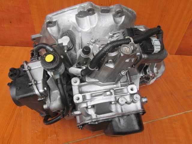
In detail: do-it-yourself repair manual transmission f17 from a real master for the site my.housecope.com.
The F17 manual transmission is essentially the same F13 manual transmission that came with the OPEL Kadett.
It was improved and tried to strengthen for all 20 years, starting with the Astra F. They succeeded until 2004, after which everything went in the opposite direction.
GM once again increased the size of the gears and slightly increased the satellites in the differential, but the quality of the heat treatment of the shafts began to decline.
In 2006 there was the penultimate modernization of the manual transmission, the output shaft in the painful increased to 27mm and a new differential.
Since 2011, there was another modernization of the F17 manual transmission The reverse speed was finalized, it began to engage through the clutch and synchronizer like other gears.
The quality of the metal and heat treatment dropped with each upgrade. The first problems with the manual transmission f17 if you have an Astra J can already arise at 80t.km run ... Wear of the secondary shaft.
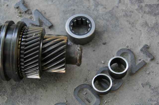
The manufacturer writes-FOR THE ENTIRE LIFE. Service life changes in the negative direction with such a recommendation .. Oil change in manual transmission should be done every 50t.km. This will somewhat extend the service life of your box. Also, check the oil level if leaks were noticed through the oil seals in the area of the drives. If, nevertheless, trouble overtook you and you heard a small hum from the manual transmission starting from 60 km.ch. It is better not to continue to operate the car any more. Metal shavings getting into the oil spreads throughout the manual transmission and damages all rubbing parts, and so you can do with replacing or repairing the secondary shaft + bearing.
Many people do not like that there are a lot of engine revolutions, but at the same time a low speed (short gears)
When driving on the highway, there is a very high fuel consumption if you go over 120-130 km / h and discomfort in the cabin from the hum of the engine at high speeds.
| Video (click to play). |
On all models of the F17 manual transmission installed on the Opel Astra H J Zafira B with a 1.6 1.8 engine, there are very short gears. 4000 rpm at the 5th speed only 135 km / h for variant C 3.94 and at -10 km / h for variant C 4.19 For the Opel Vectra S, a manual transmission F17 C3.74 or W 4.19 was installed. The last option is more interesting. Especially for driving on the highway.
What do we have in the end! 4 types of the main pair 4.19 3.94 3.74 and 3.55 The higher the number of the main pair, the lower the speed of the car in any gear at the same engine speed. As an example, if you replace the main pair 4.19 with 3.74 for 5th gear at 4000 rpm, the main pair 4.19 125 km.h and 3.74 145 km.h! That is, you can already drive 125 km / h at 3500 rpm ...
We also have 3 types of series CR WR and E. The latter is used on isitronic
By replacing the CR row with WR, we will significantly increase the vehicle speed at the same engine speed in all gears except 1st speed. It only changes when the main pair changes.
On the manual transmission F17 E 4.19 easytronic, you cannot change the main pair or row. Since the control unit compares the vehicle speed and engine speed in each gear. And if there is no compliance, the gearbox will be in emergency mode.
Summing up
1. Install output shaft 25mm (deepest carburized)
2. Assemble the 2nd generation differential only with a finger under the oil channel
3. Correctly select by weight and engine of the car, well, and operating conditions highway-city, mixed cycle-main pair and row in manual transmission
4. Fill in quality oil.
As a result, we will get a good manual transmission !! Unlike the factory one. With the right gear ratio and factory ailments eliminated.
The F17 manual gearbox is one of the worst in the Opel transmission lineup. The owners of the models Astra, Zafira, Vectra, Signum F17 often cause complaints. Breakdowns are often provoked by the fact that the manufacturer fills in oil for the entire service life of the box and does not provide for its replacement.We recommend that you regularly check its level and, if necessary, top up or completely replace it.
Among the typical breakdowns of the F17 from Opel, there is a characteristic hum at idle, which disappears when the clutch is depressed. GM designers, having estimated the number of broken F17 gearboxes, reconsidered their decision regarding oil changes. Now routine maintenance is recommended to be carried out with service intervals of up to 60 thousand km. This sometimes helps to eliminate input shaft noise.
Let's consider another typical breakdown - difficulties when shifting gears. Potential causes of the defect include wear on the gearbox stem and pins. To carry out repairs, you have to buy a stem, a set of pins and a stem oil seal. It is desirable to combine the restoration with the replacement of the transmission oil. There is no drain plug, so you have to dismantle the pallet.
The mechanics are designed in accordance with a two-shaft scheme. The box is completed with a common crankcase with main gear and differential. The splines are used to connect the input shaft to the gears. The output shaft is equipped with a driving spur gear of the main drive, synchronizers and driven gears. Forward gears are constantly engaged. But when neutral is turned on, the gears of the four gears rotate freely on the secondary shaft. To engage the forward gears, the synchronizer couplings are moved.
The manual transmission control drive includes a shift lever, a ball joint and two cables that connect the levers. The design is equipped with a bevel two-satellite differential. To maintain tightness, two oil seals are used.
Examples of typical breakdowns and repair options for manual transmissions F17 Astra J
- The appearance of vibration and noise in the box. This may be due to the weakening of the fasteners, banal damage to the gearbox mountings, gears and bearings (to combat this problem, the RVS-Master Tr5 geomodifier was developed). Less often, noise is provoked by irregularities in idle speed adjustments, the use of oil of inappropriate viscosity.
- Leaks of working fluid due to lost elasticity of oil seals, O-rings.
- Difficulties, grinding noise when shifting gears, to eliminate which you have to adjust the clutch drive, change the drive cables or the synchronizer springs.
- Knocks out gears - you need to check the shift forks and retainer springs, the gap on the synchronizer clutch.
The weak point of the F17 is the differential, which can become unusable with low mileage - up to 50,000 km. There are specific examples of how this happened on the Opel Astra. When slipping, the satellites overheat, then stick to, but in fact the factory defect has not yet been officially recognized. If, for example, the pinion axle is damaged, you have to change the differential assembly. In order to protect other mechanisms from wear and to eliminate existing defects, it is advisable to change the oil in the system and treat it with a VST composition.
RVS-Master is a friction geomodifier that builds up a cermet layer on the working surfaces. This happens after the particles of serpentinite get into the places of wear and penetrate into the near-surface layers of the metal. Effects of processing manual transmission F17 with RVS-Master:
- Decrease in noise, reduction in the number of vibrations.
- Restoration of the geometry of the gears.
- Normalization of shifts (the gearshift lever goes much easier after two processing).
- Compensation for gear wear.
Reduced wear at subzero temperatures, slippage, which is so dangerous for the F17.
What kind of kits are they? I have never met. Have a partner?
+ I'm interested in what kind of clutch repair kit is needed for f17 vin W0L0AHL69AG005377
What kind of kits are they? I have never met. Have a partner?
+ I'm interested in what kind of clutch repair kit is needed for f17 vin W0L0AHL69AG005377
People are always more willing to eat than run. R.Kipling
Astra H Caravan 1.6 + adact
Message Max_SM »09 Jan 2015 13:40
Message rodnaya »09 Jan 2015 21:15
Message Untermensch »10 Jan 2015 16:09
Message SergeyZakharov »10 Jan 2015 19:29
Message griandrej »11 Jan 2015 22:14
Message SergeyZakharov »12 Jan 2015 19:06
Message trahandberg »12 Jan 2015 21:43
Message griandrej »13 Jan 2015 00:56
Message Daimonhill »13 Jan 2015 10:57
Message Untermensch »13 Jan 2015 15:19
Daimonhill, on the isitronic case there are ears for the drives, but on the usual one they are not. Therefore, it is possible to make mechanics out of Izik, but on the contrary, you will shoot yourself, there is nothing to fix.
It's just that they rarely catch F17 before the secondary shaft ditches the case, and if there is a hole in the case, nothing can be rearranged. If the housing is intact, there is a chance, depending on the condition of the bearing seat for the secondary shaft.
Message ura10 »14 Jan 2015 17:18
Hello everyone. Yes problematic manual transmission f 17. but Mukhanik is no longer in business. I called him, he said I am not doing this. But he left a student, I wonder?
Sent after 4 minutes 42 seconds:
I buy a boo every year. Manual transmission f17 ... in Ukraine was found for 500 dollars and a master of God. So it went on for a year and a half, but the car is still standing still. : crazyeyes:
Message griandrej »15 Jan 2015 01:30
Message Daimonhill »15 Jan 2015 11:27
Message Untermensch »16 Jan 2015 10:31
Message griandrej »16 Jan 2015 11:22
Message Daimonhill »16 Jan 2015 12:29
Message Max_SM »17 Jan 2015 12:14
Message vadim + »17 Jan 2015 22:16
Message griandrej »17 Jan 2015 22:31
Message vadim + »17 Jan 2015 23:06
Message KOSTA LA COSTA »20 Apr 2015 09:04
Message Muhanik »21 Apr 2015 10:28
Message Maksota »16 May 2015 20:20
Hello everyone. Yes problematic manual transmission f 17. but Mukhanik is no longer in business. I called him, he said I am not doing this. But he left a student, I wonder?
Sent after 4 minutes 42 seconds:
I buy a boo every year. Manual transmission f17 ... in Ukraine was found for 500 dollars and a master of God. So it went on for a year and a half, but the car is still standing still. : crazyeyes:
Everything fits, did he put f17e419 - f17w419 himself? And moreover, she immediately went, just stupid with shifting the 4th and 5th gears, since the f17w 3,4,5 is shorter, I came to the electronics engineer, the composer was prescribed that W and EVERYTHING!
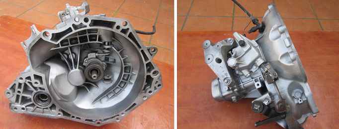
The Opel box with the F17 index dispelled the myth about the unconditional reliability of the classic "mechanics". Structurally, this gearbox largely repeats the old 4-speed manual gearbox F13, which was installed on the Kadett E. The 5-speed F15 has been installed on Opel models - Corsa, Astra, Zafira and Vectra since 1995. Depending on the year of manufacture, the box has differences in the case: until 1999, the casting of the MCP case had only side mounting, then additional holes appeared in the body for the upper mounting bracket. In 2003, a robotic transmission was created on its basis.
The F17 manual gearbox is designed to transmit up to 170 Nm of torque from the engine. The box is two-shaft, has a common crankcase with the main transmission and a bevel two-satellite differential. The gears of the input shaft are connected by splines. The output shaft is equipped with synchronizers. Forward gears are constantly engaged. The manual gearbox control drive consists of a shift lever, a ball joint and two cables connecting the levers. To maintain tightness, two oil seals are used.
The F17 box serves well and for quite a long time with engines up to 1.6 liters with a capacity of no more than 110 hp. It is clear that we are talking about rather old units. With more powerful engines up to 1.8 liters (125-140 hp) or with a turbocharged 1.4-liter unit (140 hp), the box in all its glory shows the flaws in its design: it is simply unable to "digest" high power and torque of engines, as well as the mass of heavier modern cars.
In the F17 box, perhaps only the case does not break. The main problems and symptoms of an impending breakdown can be heard and felt. Most often, this box is sent for repair due to the destruction of the secondary shaft and its bearings. Breakdown is accompanied by a howl when driving and at idle. Failure of bearings entails damage to shafts and gears, gearbox housing and differential.
The differential can become unusable by itself even with a mileage of 50,000 km, more often closer to 100,000 km.Usually, the cause of its premature wear is acceleration with slippage during which the differential satellites overheat and then stick. As a result, the axis of the satellites breaks down - for repair it is necessary to change the differential assembly.
Also, in case of faults in the F17 box, difficulties arise when shifting gears - the lever moves tight. The reason is the wear of the gearbox rod, bushings in the connection of the pins and the pins themselves. If there is a problem with knocking out gears, check for wear on the shift fork and retainer springs, as well as the play on the synchronizer sleeve.
Also, the F17 gearbox actively loses oil with age, leaving it through the oil seals. Losing oil only hastens other problems with this box.
For a long time, the F17 transmission was considered maintenance-free. However, the designers of GM, assessing the scale of the breakdowns of this box, revised the oil change regulations. The oil in the F17 manual gearbox should be changed every 60 thousand km. This sometimes helps to eliminate input shaft noise.
You can buy spare parts for Opel on our website
You will need: keys "for 10", "for 13", "for 19", "for 24", a set of hex keys, flat-blade screwdrivers (two), round-nose pliers, circlip remover, bearing puller, hammer, barbs, chisel.
1. Remove the transmission from the car (see Removing and installing the transmission). Remove any dirt from it and wash the outside.
2. Remove the speedometer drive together with the vehicle speed sensor, if any (see Checking and replacing sensors of the engine management system).
3. Loosen the reversing light switch ...
5. After unscrewing the bolts securing the body of the gearshift mechanism, remove the mechanism ...
The three bolts of the gearshift housing are not visible in the photo.
6. ... and the gasket underneath.
7. Using a screwdriver to pry the spring clip of the driver of the V-th gear shift fork ...
10. Remove the clutch slave cylinder assembly with the clutch release bearing (see. Replacing the clutch slave cylinder with the release bearing) and the rubber O-ring installed under the cylinder.
11. Remove the adapter of the hydraulic clutch release (see Replacement of the pipeline of the hydraulic clutch release).
12. Remove the intermediate tube of the hydraulic drive of the clutch release (see Replacement of the pipeline of the hydraulic drive of the release of the clutch).
13. Remove the nine bolts securing the rear transmission cover.
14. Using a screwdriver, pry off the edge of the cover in the area of the specially designed lug, separate the cover from the gasket and remove the cover.
15. Remove the cover gasket.
Replace the gasket of the rear cover of the transmission with a new one each time the connection is disassembled, as a used crimped gasket may not ensure the tightness of the seal during reassembly.
16. Remove the 5th gear synchronizer retaining ring.
17. Remove the two bolts securing the bracket for the 5th gear shift fork ...
18. ... and remove the bracket assembly with the fork.
19. Remove the crackers from the fork.
Replace worn-out crackers during assembly with new ones.
20. Install a universal puller on the V gear synchronizer sleeve ...
21. ... and press the coupling assembly with the hub off the shaft.
22. Remove the synchronizer blocking ring ...
23. ... the driven gear of the V transfer ...
24. ... and needle bearing.
25. Remove the V transfer pinion retaining ring.
26. Install the universal puller on the drive gear wheel of the V transfer ...
27. ... and press the gear off the shaft.
28. Remove the locking ring from the output shaft ...
29. ... and remove the two persistent half rings.
30. Remove the five bolts securing the intermediate casing to the gearbox housing ...
31. ... separate the intermediate crankcase from the crankcase with hammer blows through a wooden spacer supported on a special crankcase lug ...
32. ... and remove the intermediate casing together with the shafts.
33. Remove the crankcase gasket by separating it with a sharp knife.
Replace the intermediate casing gasket with a new one each time the connection is disassembled, as a used crimp gasket may not provide a tight seal when reassembled.
34. Unscrew the ten bolts securing the lower gearbox cover and remove the cover together with the gasket.
35. Separate the gasket from the cover.
Replace the gasket of the lower cover of the transmission with a new one each time the connection is disassembled, as a used crimped gasket may not ensure the tightness of the seal during reassembly.
36. Mark the position of the differential bearing adjusting nut in relation to the transmission case.
37. Remove the adjusting nut retainer bolt ...
39. ... move the adjusting nut out of place with a mounting paddle as shown in the photo ...
40. ... and, having counted the number of revolutions, unscrew the nut.
41. Remove the O-ring from the nut.
Replace a heavily crimped, hardened or frayed ring.
42. Press out the axle shaft oil seal from the nut.
43. If it is necessary to replace the differential bearings, turn the adjusting nut over, place a pair of wooden blocks and press out the outer ring of the differential bearing from the nut.
44. Remove the five bolts securing the right differential bearing cover ...
45. ... remove the cover and the O-ring from it, press out the oil seal and, if necessary, the outer ring of the bearing from the cover in the same way as they were pressed out of the adjusting nut.
46. Remove the differential assembly from the transmission case.
47. Remove the magnet from the crankcase ...
48. ... and clean it from wear debris.
49. Remove the spacer washer from the intermediate reverse gear axle.
The spacer washer of the reverse idler gear may remain in the gearbox housing when the gearbox housing and the intermediate housing are separated. Take it out from there.
50. Remove the two bolts securing the pawl bracket ...
51. ... set the rods of the forks in sequence to positions II, V and III gears and remove the bracket assembly with the pawl.
52. Use a hammer through a chisel with a blunt sting to knock out the stoppers of the gear shift fork rods ...
54. Remove the two screws securing the locking pin ...
56. ... and remove the pin from the bracket.
57. Leaning the free end of the rod on a wooden block, knock out the pin securing the fork for engaging the intermediate reverse gear with a beard ...
58. ... and remove the stem and plug.
59. From the holes in the intermediate case, remove the locking pin for simultaneous engagement of two gears.
60. Knock out the pin securing the shift fork of III and IV gears ...
61.… pull out the stem and remove the plug.
When removing the fork, the gearshift clutches must be in the neutral position.
62. Lift the leash of the V gear engagement fork and remove the III and IV gear engagement fork.
63. Pull the rod out of the crankcase and remove the drive of the V gear engagement fork.
64. With a puller for internal circlips (working in compression), squeeze the circlip of the output shaft bearing ...
65. ... and fix it in this position.
66. Knock out the pin securing the forks of gears I and II ...
67.… pull out the stem and remove the plug.
68. Using a puller for outer circlips (working for expansion), unclip the circlip of the input shaft bearing ...
69. ... and remove the input and output shafts, taking their shanks out of the intermediate crankcase.
70. Remove the reverse idler gear.
71. With a puller, remove the input shaft bearing retaining ring from the intermediate casing groove.
72. Before inspection and troubleshooting, thoroughly wash and dry the transmission parts.
73. Inspect the transmission case, intermediate case and rear cover. They should not be chipped. There should be no nicks, marks, dents, etc. on the mating surfaces. Remove minor damage with fine-grained emery paper. Replace defective parts if severely damaged.
74.Check the bearing seats. These surfaces should not show signs of wear or damage. If damaged, replace the crankcases.
75. Check the condition of the gear shift rods. If the rods are bent or there are scuffs, burrs, or dents under the retainers, replace the rods.
76. Check the condition of the gear shift forks. If they are bent or the tabs are worn out, replace these parts.
77. If oil leaks through the oil seals are detected during operation and when their working edges are worn, the oil seals must be replaced.
78. Check the condition of the bearings. If cavities are found on the treadmills and rolling elements, traces of indentation of the rolling elements on the treadmills, or if the cages are damaged, the bearings must be replaced.
79. Replace the gaskets of the intermediate case, the rear cover of the transmission and the gear shifting mechanism.
80. Clean the magnet from wear particles. If the magnet appears cracked or its magnetic properties are weakened, replace the magnet.
Assemble the gearbox in the reverse order of disassembly, taking into account the following.
1. Before assembly, liberally lubricate all rubbing parts with gear oil.
2. Assemble all threaded connections using an anaerobic thread lock.
3. Before installing the output shaft in the intermediate crankcase, squeeze the retaining ring with round-nose pliers and secure with a wire in a compressed state. Remove the wire after installing the shaft in the crankcase, making sure that the ring fits into the grooves of the crankcase without distortions.
4. When installing the differential, if its bearings have not been changed, turn the adjusting nut of its bearings by the same number of revolutions as when unscrewing, until the marks applied during disassembly are aligned.
5. If you changed the bearings of the differential, after installing it, adjust the preload of the bearings to the value of the moment of resistance to rotation of the bearings by tightening or unscrewing the adjusting nut. For new bearings, the moment of resistance should be 2 Nm (0.2 kgf If the bearings have not been changed, then the moment of resistance should be 1 N m (0.1 kgf m).
6. Before installing the lower transmission cover, lubricate the gasket with grease.
5-speed gearbox F17
1. Remove the transmission assembly. Remove the mounting bolts and remove the transmission housing assembly.
2. Connect the rear part of the transmission housing to the special tool KM-552 (2), as shown in the figure below.
3. Install the gearbox on the special stand KM-113-2 (1) using the special tool KM-552, as shown in the figure below.
4. Remove the bearing support (1) together with the cam (2) from the gearbox housing, as shown in the figure below, by unscrewing the two fastening bolts.
Microencapsulated mounting bolts installed.
5. Remove the fifth gear driven gear as shown in the illustration below.
- Remove the retaining ring (1) shown in the figure below from the synchroniser housing.
- Install the special tool KM-559-A (2) and press the 5th gear and synchronizer housing off the gearbox shaft, as shown in the figure below.
- Remove the two fifth gear needle bearings from the gearbox shaft.
6. Remove the retaining ring (1) of the 5th gear drive gear (2) from the transmission shaft (3) as shown in the figure below.
7. Install the special tool KM-553-A (1) on the 5th gear drive gear, as shown in the figure below.
Make sure the special tool is installed properly on the fifth gear.
- The stop of the special tool (2) must be installed on the gearbox shaft as shown in the figure below.
find a chelovekservice in the city that is engaged in the repair of boxes, remove the box yourself and give them a complete bulkhead and replacement of consumables.
Usually such a procedure costs about 15 thousand. They will tell you where the wear is and why.
for a week, as it got colder, I select oil with a lower threshold for fluidity loss, stopped at Castrol 4008177071812 freezes at -60. viscosity 70W-80. I think for our climate it is the most, even though the second one will stick normally.
but in general, at the Matiz club people pour into the ATF box and are happy like elephants, they say the first one turns on perfectly even at 30 km, the second and the back one turns on easily. the guys from the Aveo club support them.
on the rest of the ZhyEm forums, the runs have long exceeded 200 thousand. but, they pour strictly Motul's THIRD dextron. I'll probably spend a thousand and buy just a synthetic gear oil with a lower freezing point.
if you look from the mechanical side, if not for the synchronizers, then the difference with the automatic transmission is not great. in the automatic transmission the same bearings, oil seals, gears, including helical. in old Mercedes in manual transmission there is ATF, but in those boxes there are synchronizers made of ferrous metals. the confirmation
the torque converter contains about 3.5 liters, in the pallet there are also about 3, about 1.5 liters. leaves along the cooling lines, the rest is distributed along the valves and channels of the valve body, the bearings and gears are lubricated (swimming, one might say) with “residues”, there is no supply of liquid under pressure to them, it simply moves from top to bottom through the drain channels into the pan. In automatic transmission, ATF also plays the role of transmitting torque and cooling and lubrication, this also affects the volume.
Perhaps with my family and I would have switched, but before me it was changed, and now even at minus 20 it’s torment to stick in the second (the synchronizer simply cannot push through the oil and equalize the rotation speeds), and even about switching from the second to the first floor, it’s a dream in general, horseradish stick if you go a little faster than 5 km! of course it could be attributed to the wings, backlash, gaps if I had not removed all this in the summer. the lever moves clearly, does not dangle, the rocker is adjusted as expected, but it does not help.
it is not necessary to take jars, it is enough to read the parameter in the specification: Pour point.
I will add that I am not agitating anyone to use ATF and I will not use it myself.
Opel Astra, Chevrolet Viva & Opel Zafira Club
Moderator COLON Remont
Message NikitaRUS »Fri 08 Jun, 2012 21:39
Message Grunt »Fri 08 Jun, 2012 22:25
Sequence:
- remove 5th gear
- remove the reverse gear
- remove the forks switch. 1-2 and 3-4
- release the bolster stopper. secondary shaft
- knock the primary shaft out of the bearing, while removing the secondary shaft.
It's like in a morgue: an autopsy will show.
Do you think everything is so bad ?? No, it's much worse.
Message HEAVY METAL »Sun 10 Jun, 2012 00:14
Message Grunt »Sun 10 Jun, 2012 00:51
It's like in a morgue: an autopsy will show.
Do you think everything is so bad ?? No, it's much worse.
Message pasha32 »Sun Jun 10, 2012 11:35 am
Message pasha32 »Sun Jun 10, 2012 11:36 am
Message HEAVY METAL »Sun 10 Jun, 2012 21:48
Message Grunt »Sun 10 Jun, 2012 21:49
It's like in a morgue: an autopsy will show.
Do you think everything is so bad ?? No, it's much worse.
Message HEAVY METAL »Sun 10 Jun, 2012 21:56
Message HEAVY METAL »Sun 10 Jun, 2012 22:05
You will need: keys "for 10", "for 13", "for 19", "for 24", a set of hex keys, flat-blade screwdrivers (two), round-nose pliers, circlip remover, bearing puller, hammer, barbs, chisel.
1. Remove the transmission from the car (see Removing and installing the transmission). Remove any dirt from it and wash the outside.
2. Remove the speedometer drive together with the vehicle speed sensor, if any (see Checking and replacing sensors of the engine management system).
3. Loosen the reversing light switch ...
5. After unscrewing the bolts securing the body of the gearshift mechanism, remove the mechanism ...
The three bolts of the gearshift housing are not visible in the photo.
6. ... and the gasket underneath.
7. Using a screwdriver to pry the spring clip of the driver of the V-th gear shift fork ...
10. Remove the clutch slave cylinder assembly with the clutch release bearing (see. Replacing the clutch slave cylinder with the release bearing) and the rubber O-ring installed under the cylinder.
11. Remove the adapter of the hydraulic clutch release (see Replacement of the pipeline of the hydraulic clutch release).
12.Remove the intermediate tube of the hydraulic clutch release (see Replacing the pipeline of the hydraulic clutch release).
13. Remove the nine bolts securing the rear transmission cover.
14. Using a screwdriver, pry off the edge of the cover in the area of the specially designed lug, separate the cover from the gasket and remove the cover.
15. Remove the cover gasket.
Replace the gasket of the rear cover of the transmission with a new one each time the connection is disassembled, as a used crimped gasket may not ensure the tightness of the seal during reassembly.
16. Remove the 5th gear synchronizer retaining ring.
17. Remove the two bolts securing the bracket for the 5th gear shift fork ...
18. ... and remove the bracket assembly with the fork.
19. Remove the crackers from the fork.
Replace worn-out crackers during assembly with new ones.
20. Install a universal puller on the V gear synchronizer sleeve ...
21. ... and press the coupling assembly with the hub off the shaft.
22. Remove the synchronizer blocking ring ...
23. ... the driven gear of the V transfer ...
24. ... and needle bearing.
25. Remove the V transfer pinion retaining ring.
26. Install the universal puller on the drive pinion of the V transfer ...
27. ... and press the gear off the shaft.
28. Remove the locking ring from the output shaft ...
29. ... and remove the two persistent half rings.
30. Remove the five bolts securing the intermediate casing to the gearbox housing ...
31. ... separate the intermediate crankcase from the crankcase by hammer blows through a wooden spacer supported on a special crankcase lug ...
32. ... and remove the intermediate casing together with the shafts.
33. Remove the crankcase gasket by separating it with a sharp knife.
Replace the intermediate casing gasket with a new one each time the connection is disassembled, as a used crimp gasket may not provide a tight seal when reassembled.
34. Unscrew ten bolts securing the lower gearbox cover and remove the cover together with the gasket.
35. Separate the gasket from the cover.
Replace the gasket of the lower cover of the transmission with a new one each time the connection is disassembled, as a used crimped gasket may not ensure the tightness of the seal during reassembly.
36. Mark the position of the differential bearing adjusting nut in relation to the transmission case.
37. Remove the adjusting nut retainer bolt ...
39. ... move the adjusting nut out of place with a mounting paddle as shown in the photo ...
40. ... and, having counted the number of revolutions, unscrew the nut.
41. Remove the O-ring from the nut.
Replace a heavily crimped, hardened or frayed ring.
42. Press out the axle shaft oil seal from the nut.
43. If it is necessary to replace the differential bearings, turn the adjusting nut over, place a pair of wooden blocks and press out the outer ring of the differential bearing from the nut.
44. Remove the five bolts securing the right differential bearing cover ...
45. ... remove the cover and the O-ring from it, press out the oil seal and, if necessary, the outer ring of the bearing from the cover in the same way as they were pressed out of the adjusting nut.
46. Remove the differential assembly from the transmission case.
47. Remove the magnet from the crankcase ...
48. ... and clean it from wear debris.
49. Remove the spacer washer from the intermediate reverse gear axle.
The spacer washer of the reverse idler gear may remain in the gearbox housing when the gearbox housing and the intermediate housing are separated. Take it out from there.
50. Remove the two bolts securing the pawl bracket ...
51. ... set the rods of the forks in sequence to positions II, V and III gears and remove the bracket assembly with the pawl.
52. Using a hammer through a chisel with a blunt sting, knock out the plugs of the retainers of the gear shift forks ...
54. Remove the two screws securing the locking pin ...
56. ... and remove the pin from the bracket.
57.Leaning the free end of the rod on a wooden block, knock out the pin securing the fork for engaging the intermediate reverse gear with a beard ...
58. ... and remove the stem and plug.
59. From the holes in the intermediate case, remove the locking pin for simultaneous engagement of two gears.
60. Knock out the pin securing the shift fork of III and IV gears ...
61.… pull out the stem and remove the plug.
When removing the fork, the gearshift clutches must be in the neutral position.
62. Lift the leash of the V gear engagement fork and remove the III and IV gear engagement fork.
63. Pull the rod out of the crankcase and remove the drive of the V gear engagement fork.
64. With a puller for internal circlips (working in compression), squeeze the circlip of the output shaft bearing ...
65. ... and fix it in this position.
66. Knock out the pin securing the forks of gears I and II ...
67.… pull out the stem and remove the plug.
68. Using a puller for outer circlips (working for expansion), unclip the circlip of the input shaft bearing ...
69. ... and remove the input and output shafts, taking their shanks out of the intermediate crankcase.
70. Remove the reverse idler gear.
71. With a puller, remove the input shaft bearing retaining ring from the intermediate casing groove.
72. Before inspection and troubleshooting, thoroughly wash and dry the transmission parts.
73. Inspect the transmission case, intermediate case and rear cover. They should not be chipped. There should be no nicks, marks, dents, etc. on the mating surfaces. Remove minor damage with fine-grained emery paper. Replace defective parts if severely damaged.
74. Check the bearing seats. These surfaces should not show signs of wear or damage. If damaged, replace the crankcases.
75. Check the condition of the gear shift rods. If the rods are bent or there are seizures, burrs, or dents under the retainers, replace the rods.
76. Check the condition of the gear shift forks. If they are bent or the tabs are worn out, replace these parts.
77. If oil leaks through the oil seals are detected during operation and when their working edges are worn, the oil seals must be replaced.
78. Check the condition of the bearings. If cavities are found on the treadmills and rolling elements, traces of indentation of the rolling elements on the treadmills, or if the cages are damaged, the bearings must be replaced.
79. Replace the gaskets of the intermediate case, the rear cover of the transmission and the gear shifting mechanism.
80. Clean the magnet from wear particles. If the magnet appears cracked or its magnetic properties are weakened, replace the magnet.
Assemble the gearbox in the reverse order of disassembly, taking into account the following.
1. Before assembly, liberally lubricate all rubbing parts with gear oil.
2. Assemble all threaded connections using an anaerobic thread lock.
3. Before installing the output shaft in the intermediate crankcase, squeeze the retaining ring with round-nose pliers and secure with a wire in a compressed state. Remove the wire after installing the shaft in the crankcase, making sure that the ring fits into the grooves of the crankcase without distortions.
4. When installing the differential, if its bearings have not been changed, turn the adjusting nut of its bearings by the same number of revolutions as when unscrewing, until the marks applied during disassembly are aligned.
5. If you changed the bearings of the differential, after installing it, adjust the preload of the bearings to the value of the moment of resistance to rotation of the bearings by tightening or unscrewing the adjusting nut. For new bearings, the moment of resistance should be 2 Nm (0.2 kgf If the bearings have not been changed, then the moment of resistance should be 1 Nm (0.1 kgfm).
| Video (click to play). |
6.Lubricate the gasket with grease before installing the gearbox lower cover.


