In detail: DIY repair of a Polaris heater from a real master for the site my.housecope.com.
At the present stage, electronic control units (ECUs) are widely used in household appliances. Refrigerators, washing machines, even irons are equipped with similar devices. This is not surprising, since in temperature control systems and control mechanisms, ECUs are so versatile that it is difficult to imagine a replacement for them. The use of electronic control units in climatic equipment is the most relevant. This allows you to set a certain operating mode of the equipment, as well as visually check the current state of the set parameters. Mechanically controlled instruments do not have this capability.
One of the representatives of climatic equipment are ceramic heaters. They are produced by many manufacturers. Let's consider the design and repair of such a heater using the example of the PCWH model manufactured by POLARIS.
Specifications and main functions:
- automatic maintenance of the set temperature in the range of 18-30 ° С;
- LED symbolic indicator of operating modes;
- remote control;
- supply voltage: 220 230 V / 50 Hz.
The heater consists of a ceramic heating element, a tangential fan, a fan electric motor, a blind stepper motor, an ionizer unit and an ECU, a remote control (RC). The disassembled view of the fan heater is shown in Fig. one.
The electronic control unit is made on two boards - a power one, as well as an indication and control board, interconnected by a loop of wires. The block diagram of the fan heater ECU is shown in Fig. 2.
| Video (click to play). |
The power board includes a power supply unit and load switching elements - fig. 3.
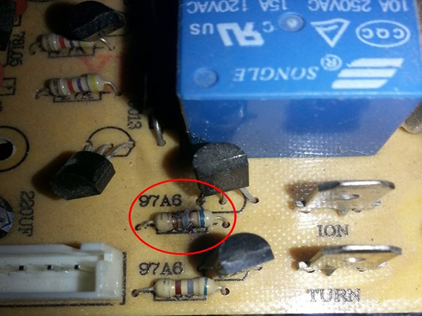
The power supply unit consists of a step-down transformer, a bridge rectifier and a stabilizer (pos. 1, fig. 3). An integrated circuit 78L05 is used as a stabilizer. The heating elements are controlled by electromagnetic relays. The fan motor and the ionizer unit are commutated by triacs (pos. 2, fig. 3). The device uses Motorola MAC97A6 triacs. They are designed for switching loads up to 800 mA (at voltages up to 400 V).
The indication and control board is shown in Fig. 4 and 5. The board contains a symbolic LED indicator, a microcontroller (1), a stepper motor driver microcircuit (2), a stepper motor connector (3), a temperature sensor connector (4), an IR receiver (5), a power board connector (6) and control buttons connector (7).
On the soldering side of the display and control printed circuit board, there are LED indicator driver microcircuits. In fig. 5 they are marked with a rectangle.
The mechanical part of the fan heater can be attributed to the shutter drive system, which is shown in Fig. 6 and 7.
Possible malfunctions and methods of their elimination
The fan heater does not turn on
The integrity of the thermal fuse TF1, the reliability of the CP2, CP6 connectors and the resistance of the primary winding of the power transformer are checked. If during the check the malfunction did not come to light, then check the voltage of +5 V at the output of the stabilizer. Failure of the stabilizer microcircuit is the most common malfunction. If the voltage of the stabilizer is normal, but the defect persists, you should check and replace the 1000 microfarad capacitor in the rectifier filter circuit (pos. 1, fig. 3).
The most likely cause of this defect is the failure of the IR emitter or the remote control's quartz resonator.Also, the reason may be the poor quality of soldering of the microcontroller pins of the remote control or the pins of the IR receiver. This malfunction in most cases is eliminated by soldering the board after a thorough examination of the corresponding elements.
First of all, it is necessary to check whether the fan rotor rotates freely - if its impeller rotates easily, then the electrical part of the drive is checked. A multimeter is used to check the integrity of the windings of the fan electric motor, as well as the capacity of the working capacitor C1 (Fig. 2). The elements of the control circuit of the electric motor are checked, the quality of the soldering of their terminals is inspected (pos. 2, fig. 3).
The quality of the soldering of the elements in the control circuit of the winding of the electromagnetic relay on the power board is examined. The relay itself and the quality of the terminals on the terminals of the heating elements are checked.
The mechanical part of the drive (Fig. 6, 7) of the blinds is examined. The reliability of the contact in the CN3 connector (pos. 3, Fig. 4) on the indication and control board is checked, as well as the integrity of the stepper motor leads.
Malfunctions associated with the indication and control board are extremely rare, and they are most often associated with the so-called "cold soldering" or microcontroller failure.
Regardless of the quality, sooner or later, almost all electric heaters start to heat poorly, do not turn on or no longer heat at all.
Self-repair of an electric heater is not very difficult, since this class of devices is often not considered a complex device.
In everyday life, people use a wide variety of electric electric heaters: electric infrared fireplaces, convectors, fan heaters and a variety of oil radiators. For all such devices, regardless of design features, nichrome serves as a heating element.
It should be noted that the simpler the design of the heater, the longer such a device will work, and who will find it easier for her husband to understand the breakdown and repair it.
For a quick and effective repair, first of all, you need to understand how the heater works.
Regardless of the type of such devices, they all have basic common elements.
Heaters are equipped with one or two key switches which you can select one or two heating elements that will heat, as well as indicator lamps for the operation of heating elements.
The heating element may have not two contacts, but three, with two separated heating coils inside.
Immediately after the power cord with a plug, there may be a protective thermal fuse, which will automatically turn off the heater after overheating, for example, if you cover the convector from above with a towel.
There may also be a tilt sensor, which will be triggered if, for example, the convector falls or turns over.
In addition to the thermal fuse, there can also be a “circuit breaker” - an overcurrent fuse, for other emergencies.
Any diagnostics begins with disassembling the heater, but before disassembling it, you must turn it off and unplug it.
We unscrew the screws of the case, most likely the case of the control panel. Having reached the connecting control panel with a thermostat, thermostat and other elements, we begin the test with the continuity of the power cord.
Next, we check the operation of all control keys and toggle switches - calling them with a tester. Then all sequential circuits.
Thermostat is checked by a tester and it should give out zero resistance (short circuit) or close to zero on the contacts, this will indicate the health of the thermostat.
In addition to the health of the heater elements themselves, the cause of the breakdown can also creak in poor and unreliable contact of the conductors, over time, due to the difference in materials, they oxidize and rot away, so at this point you should also pay attention.
Then the protective elements are checked: the position sensor and the thermal fuse.
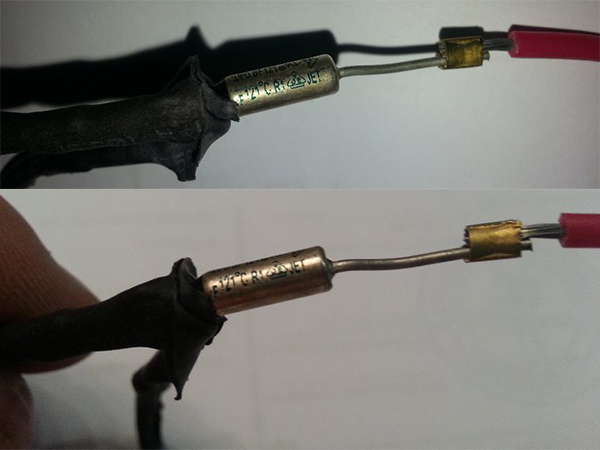
Thermal fuse they call the tester, in good and cold condition, there should be zero resistance (short circuit) on its contacts.
There can be several such thermal fuses in one case, and as a rule, the larger the case, the more thermal fuses it contains.
It should be noted that the thermal fuse may be working (serviceable), but due to the heavily soiled filters and convection holes, they can instantly trigger and turn off the heater.
What is it like position sensor, so it is, in most structures, some kind of weight that, when the heater is tilted or dropped, affects the mini-switch, which already opens the voltage. A serviceable position sensor, in the normal vertical position of the heater, on its contacts should have zero resistance (short circuit).
The main decisive point will be checking the heating Heating elementov. In large heaters, there are usually several of them, most often there are two of them. And often the reason for insufficient heating of the room is the failure of one of the heating elements.
In most cases, the heating element cannot be repaired and is replaced with a similar one.
How to check the heating element? The resistance on its contacts may be different, depending on the specific device, but it should definitely ring out. The approximate resistance values can be in the range of 20 - 100 ohms.
The heater does not turn on.
There may be several reasons. Check the outlet, plug and power cord. Then disassemble and make sure that there is a mains voltage inside the device, it is best to use a 40W control lamp for this.
The voltage on the serial circuit, thermal fuse, thermostat, thermal switch, heating element is checked
The live test should be carried out carefully or use the resistance dialing method (with a multimeter) already without voltage.
The heater turns on but does not heat.
The heater blows the air but does not heat it, such a situation clearly indicates a malfunction of the heating element, one of the sections of the spiral may be damaged, it is necessary to carefully examine the entire length of the nichrome conductor, and also ring the heating element itself with the tester, the resistance should be somewhere around 70 Ohm ...
In the event of a visible rupture or burnout of the nichrome conductor, you can try to restore it if you pull the broken conductors a little to the center and carefully twist them with a margin to each other, then firmly insert the “connection” back, but so that it does not shift or close during operation accidentally on adjacent turns of the spiral.
Also, the reason for this work may be a thermal fuse or bimetallic plates of the thermostat. In a cold state, they must be closed, sometimes it becomes necessary to clean them to improve the reliability of contact. Serviceable bimetallic plates should open from the heat of the soldering iron.
The fan heater heats up but the fan does not spin (does not blow).
If the blades are in good working order and are not wedged anywhere, then most likely the reason is in the engines.
But still, first you need to make sure that voltage is supplied to the engine. Make sure its shaft turns easily and effortlessly.
Then the engine can be checked with a multimeter, its contacts should ring and show at least some resistance.
If necessary, the motor can be disassembled and inspected inside, severe contamination is possible. Ring the windings, clean the manifold assembly and inspect the reliability of the brushes. It may be necessary to drip engine oil into the bushings of the driving part of the engine.
If the windings are burned out, the motor must be replaced.
The heater shuts down (due to overheating)
There may be several reasons.For example, a large heating area and a low-power convector, as a result of constant operation, the body and internal elements overheat, including overheating protection elements that turn off the device.
In other cases, it may be caused by incorrect installation of the Convector. It is necessary to organize a free flow of incoming air to the lower part of the heater and a free outflow of hot air from the upper part of the convector, there is nothing to cover it with and create resistance to heat escape from the convector.
The oil cooler is leaking.
Self-repair in such cases is a difficult and thankless task. Adhesives and sealants are useless in this case.
To seal the holes, it is necessary to drain the oil, fill with water and using inverter welding for thin sheets. Boil the hole, having previously cleaned the place from paint and corrosion.
With constant oil leakage, it should be understood that oil will still need to be topped up, since for the effective operation of such a heater, 90% of the volume of oil from the total capacity of the oil "tank" is necessary, the rest of the space should be occupied by air, it plays the role of a kind of cushion when oil is spreading when heating.
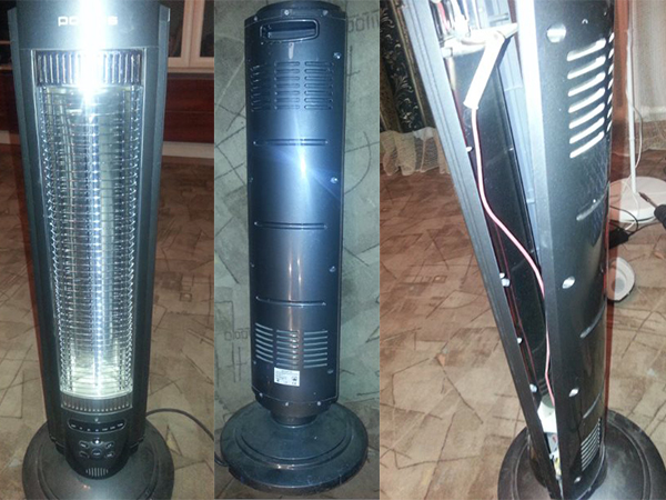
The 800W carbon fiber heater saves as an additional heating.
He worked for me on a large area, but for spot heating. It's like when you stand near him that warmth.
Has two protections. One from overheating and the other from falling. That is, if you suddenly knocked it over, it automatically turns off. There are two more heating modes: 800W or 400W, plus it has a slight translational rotation. But it is convenient to use these functions only from the remote control and it is very inconvenient without the control panel, since all the buttons are located at the bottom of the heater.
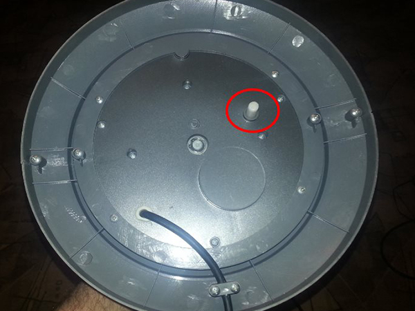
The photo shows the fall protection button.
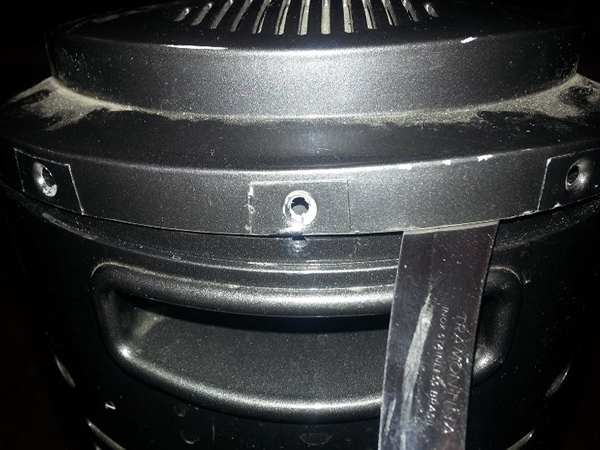
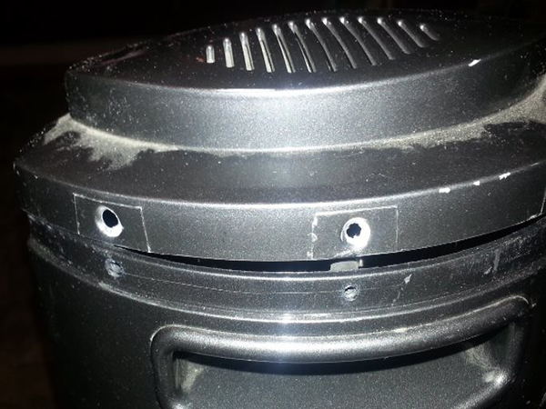
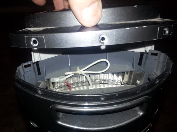
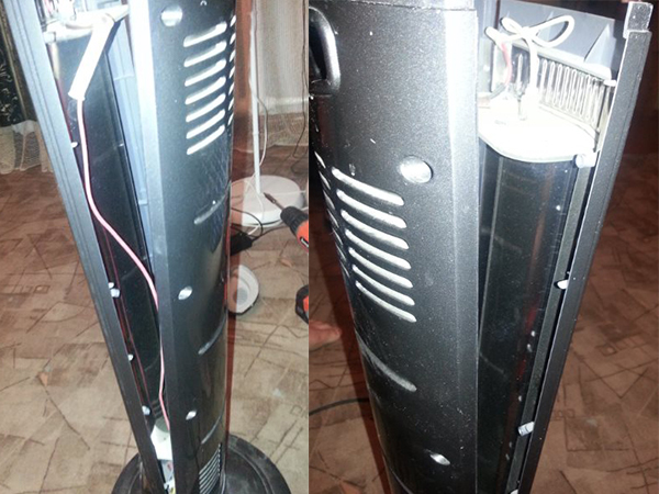
At one point, it just stopped heating. Everything worked except the spiral. It was decided to disassemble and look for the reason there. With a screwdriver, I unscrewed all the screws on the back wall. The sequence for removing the top cover, see the photo below.
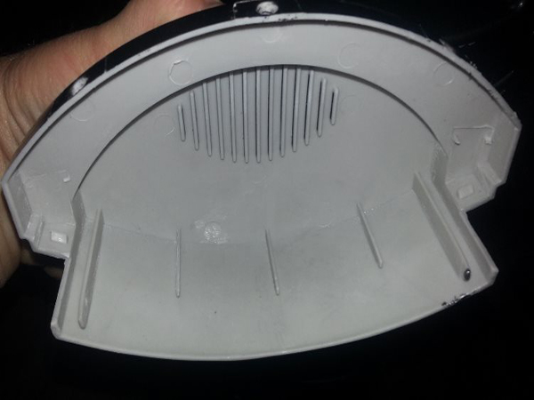
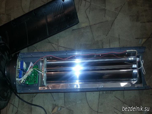
Then you need to remove the back cover of the heater. And now the filling of the heater is exposed in front of us.
ATTENTION. BEFORE DISASSEMBLING, ALWAYS DISCONNECT THE APPLIANCE FROM THE 220V MAINS.
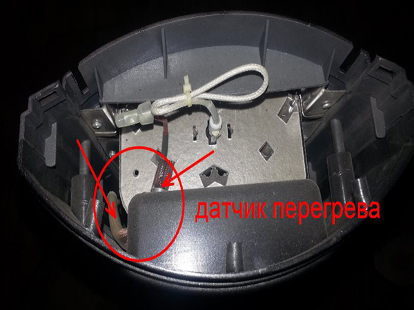
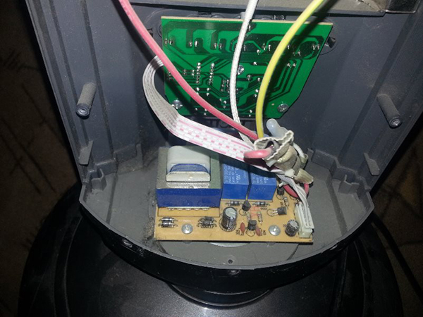
We visually inspect everything.
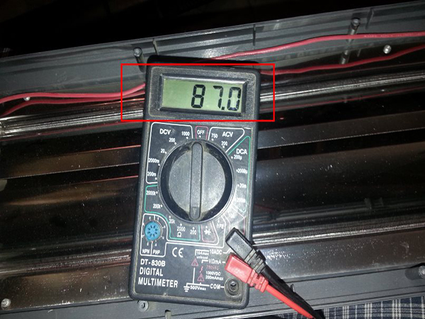
I checked the heating element with an ommer. Resistance 87 Ohm. My most important suspicion was not confirmed.
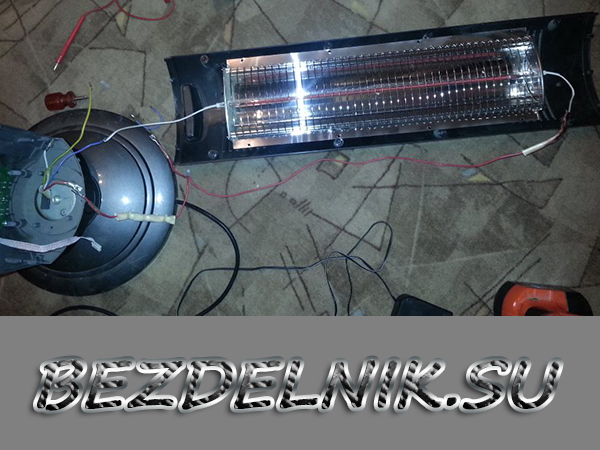
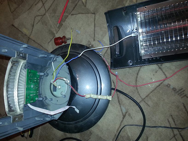
Rang out the power wires and connected directly to the heating element, but. the miracle did not happen. I had to find out the reason further. The overheating sensor remained untested in this chain. I cut it out and again connected everything directly and now everything worked.
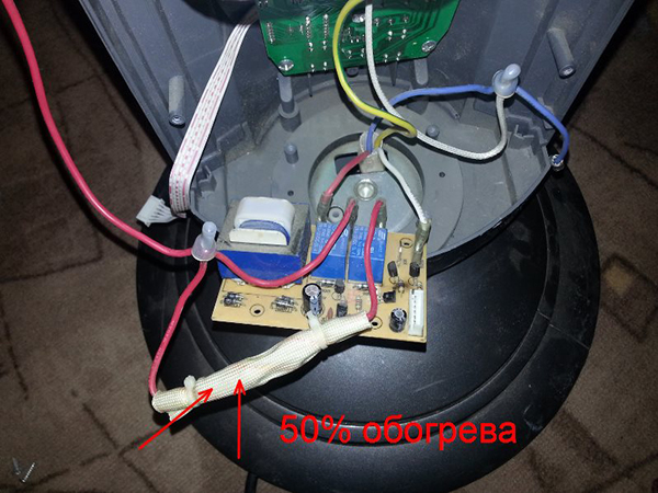
It remains to connect everything tightly and insulate. It was decided to start at half power (by choosing the appropriate wire) because now the device is without an overheating sensor. The drop protection design remains operational.
And here is the hero of our celebration.
We assemble in the reverse order and continue to enjoy the warmth 🙂
Bimetallic plates are the basis! Household heating appliances were marked, the electric kettle was conquered, and right under the button they were located. Thanks to the bimetallic plate, the device turns off after waiting for the right moment in time, driven by steam, with a brisk click. Oil heaters are equipped with a similar mechanism, only more complicated. More reminiscent of what was seen in the iron, mostly of the old modification. The screw mechanism is set in motion by the thermostat knob, pressing the contact more or less against the bimetallic plate (a slightly simplified interpretation, but the approximate meaning is this). They say that it is better to see once than to try ... to hear a hundred times. Meet fresh photos before the model is copied by competitors.The story about repairing an oil heater with your own hands will be based on the pictures taken.
It is good to cover the oil heater with clothes to dry. The only type of appliance where the owner will avoid fatal consequences. The only thing is that on the side of the accordion container there is an extension equipped with electronic filling; avoid covering the compartment. The oil heater device includes the following elements:
Emergency shutdown sensor (thermal fuse, relay)
- A container filled with oil. Appearance - a poured accordion, heating up to a decent temperature, do not touch it with your hand. When it comes to drying things, put heat-tolerant ones fearlessly. The container is sealed, but there is 15% air inside. Try to put the oil heater upside down, roll it on one side, return the load to the wheels. Heard thuds scare mice: air bubbles burst inside. Water is not used by the heater, it will quickly evaporate, the corrosion of the body will become significant, the manufacturing technology would require the complete exclusion of air from the working fluid (water + oxygen = the most powerful oxidizing agent of living nature). The coefficient of thermal expansion of the most common liquid on the planet is ten times higher than that of steel. It's not good if the tank bursts.
- The lower part of the end of the accordion contains a heating element, to which the electronics compartment clings. The oil heater has no pump and works by natural oil recirculation. The current starts up from the heating element, then the liquid goes down at the opposite end of the battery. While working, it emits the vibration of the spiral, which is audible, under the influence of alternating voltage. The effect is unavoidable, due to the influence of the Earth's magnetic field. The boiling point is above 100 ºС (150-200), avoid touching the container, until the phase state changes, the liquid is not brought due to the prohibition of the use of water: the container will rupture. TEN double (two spirals), will allow more flexible regulation of heating.
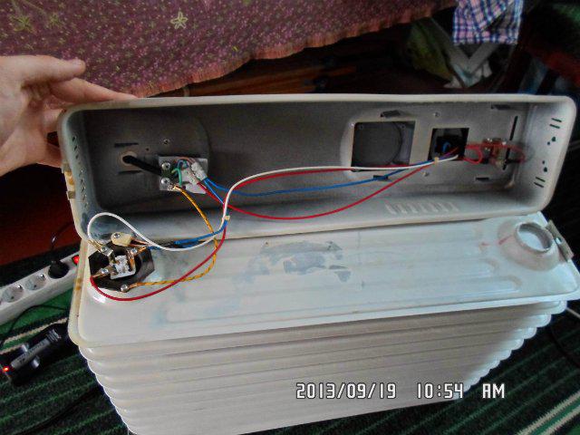
- There is a thermal fuse not far from the heating element. The device will not allow a fire to happen, if suddenly oil leaks out, the temperature relay breaks. The oil heater would work hard when the copper heating element began to melt. Oil will leak out - high temperature through the housing will cause the stuck-on thermal fuse to trip. The structure distinguishes between bimetallic (reusable) or wire (disposable). The photo shows the presence of a clearly blackening tablet above the heating element: a thermal fuse (see the first photo of the review), or a thermal relay (determined by the design).
Steel profile connecting the electronics compartment and the heater accordion
- The relay is located at the top. The main difference from the iron is visible: there is no contact with the body. It can be seen that the thermal relay simply tramples the air. An oil heater resembles an electric kettle in a marked feature, in which the bimetallic plate is often exposed to steam penetrating through a special opening in the case. A thermal relay is an adjustment mechanism, a thermal fuse is designed to localize the case of failure of standard equipment.
- The pictures show: there are two switches, each has a phase, the ground of the heating element, one wire of the thermal relay. This redundancy allows the indicator lamps to glow. One phase is not enough to provide the Joule-Lenz effect. The manufacturer does not know in advance which side the user will plug in the plug, whether the blue (red) wire will be neutralized, and is exposed to 230 volts.
The electrical part differs little from an iron, an electric kettle, a water heater. You can turn on both spirals of the heating element at the same time, separately. In the latter case, the oil heater will take longer to reach the mode. There is a chance that in a cold room the structure will work without interruption at all.
Earth's magnetic field researcher listens to the whirring of an oil heater coil
Close the air passage holes in the electronic circuit - nothing will burn, the oil heater will turn off ahead of time, restart will not take place soon, a drying woolen sock will prevent the flow of a fresh jet. The bottom of the casing of the electronic unit is cut with supply slots. The air leaves the floor, it follows, bypassing the wires, reaching the upper exit. Along the way, the bimetallic plate estimates the moment when heating stops.
The photographs of the oil heater show: the electronic unit is sealed in one piece with the accordion. This is not true. Do not cover hides a pair of screws, the retaining bracket is held in place by a spring in the bottom. It is clearly visible with the naked eye, explanations are unnecessary:
- the spring is unfastened;
- the bolts are unscrewed.
Inside the casing of the oil heater, most of the electrical connections are made with detachable terminals. If necessary, remove the switches, the bimetallic relay by unscrewing the screws from the inside, disconnecting the wires. Please note: the heating element is tightly sealed. Shows the desire of manufacturers not to allow anyone inside.
The cunning technician knows how to get to know each other
The heating element breaks more often, the tank leaks. The oil heater becomes completely unusable. The relay will last for years. Today, Soviet irons are widespread, they are still workable. It is impossible to repair the mechanism. It is necessary to clean oxidized contacts with alcohol. Repair of electronic filling is limited to the replacement of elements mainly. Thermal fuses are too lazy to repair: it is difficult to calculate the response temperature. Masters avoid taking responsibility. Keys, relays should be cleaned from time to time.
The main thing is the replacement of heating elements, oil, repair of holes. Those who want to take it should know: air is certainly stored in the tank. Acts as a cushion when the oil begins to expand. Protects the tank from bursting. When replacing, use transformer oil, waste oil is not suitable, it will cause the heating element to build up with scale.
Synthetic varieties are incompatible with mineral varieties. Those who wish can be well interpreted by the old-timers of automobile forums. The mechanism is cleaned of oil if there is no certainty which type is filled in before repair.
Avoid soldering the tank. Take non-tin solder - brass, copper-phosphorus, silver, use a torch. Refrigerator repairman equipment will do. It is recommended to fill the inside of the tank with water to avoid fire. Accordingly, after work, the container must be dried. Before filling the oil is evaporated at a temperature of 90 ºС. Beware of persistently heating the liquid - it will begin to oxidize, burn. Of course, you can freeze the oil. A thin stream is passed by a trough having a negative temperature. The oil is filled to 90% of the capacity of the oil heater; it can be measured in any available way, with water.
How to remove the heating element depends on the design. There is information about collapsible and non-collapsible versions. Try to select a heating element of the same power. The sheath is made of copper tubes. The tank of oil heaters is steel, there is a possibility of corrosion caused by the formation of galvanic couples.
Small holes can be screwed in with bolts. Lay the thread with putty, apply heat-resistant sealant. Leaks are difficult to avoid. A sealant alone is not enough, heating-cooling cycles will cause cracks. No wonder the body is made with an accordion. The structure of the metal dampens the lion's share of deforming loads.
We have listed the main types of malfunctions. Self-repairing oil heaters, when it comes to holes, is a laborious, thankless task. However, have an inverter for welding thin sheets at hand, localize the hole. It is important to remove, by repairing the rust layer, the corroded areas, to allow the seam to catch on. Repairing an oil leak has a chance of being successful.
The fall sensors fell silent.The input of the electric circuit of the oil heater is preceded; at a certain roll, the power supply of the device is turned off. Checking the operation of the element is not difficult. Lay on one side, ring the contacts. Repair of the oil heater drop sensor is not justified by the risk caused by improper operation. Along with the thermal fuse, we see an element that ensures operational safety. Information regarding the repair has been presented, we hope the story is useful for novice craftsmen. The pros themselves know how to fix the problem.
Electric oil heaters are common devices and are highly reliable, but it happens that even such simple devices fail. In a situation where the heater does not turn on or does not heat well, you need to check the availability of the warranty card. With a valid warranty, it should be taken to a service center. But it often happens that such an opportunity is absent, and the repair of the oil heater will have to be done by hand. In this case, it is necessary to consider the possible causes of breakdowns and find out methods for their elimination.
Different models of heaters can have a different number of heating elements, thermostats and switching devices for connection and connection. They also have forced air systems to enhance convection and increase heat transfer.
The heating elements are housed in a rugged, sealed, ribbed, oil-filled housing covered with a durable dielectric powder coating. The switches are attached to the outside of the heater. All connections of heating devices and external control elements are connected through a hermetically sealed sleeve.
The circuit of the oil heater is constructed as follows: the supply wire with a plug is connected through switches and a thermal fuse to the heating elements. In this case, the thermal fuse provides a break in the supply circuit in the event of an emergency overheating of the device. The latest models of oil heaters are also equipped with a position sensor that turns off the device in the event of a fall or critical deviation from the operating state.

