In detail: do-it-yourself repair of a Chevrolet Niva handout from a real master for the site my.housecope.com.
We unscrew the second nut, keeping the shafts from turning with a mounting blade inserted between the bolts.
Remove the nut and washer. Remove the drive shaft flange.
. press the front bearing.
Remove the rear bearing in the same way.
We put marks on the front and rear differential housings so as not to disturb the balance of the unit during assembly.
We remove the rear bearing of the intermediate shaft in the same way as the front bearing of the drive shaft.
To check the technical condition of the transfer case parts, we thoroughly clean and rinse them with kerosene or white spirit.
There should be no cracks on the crankcases and box covers, and wear or damage (chips, dents, etc.) should not be allowed on the surfaces of the bearing bores. Damage to the crankcase and cover mating surfaces can cause shaft misalignment and oil leakage. Minor damage
we fix it with a file; in case of significant damage and wear, we replace the parts with new ones.
Damage is not allowed on the working surfaces, threaded part and shaft splines. There should be no scoring or wear marks on the seating surfaces of the gears. Chipping or excessive wear of the gear teeth is not allowed. Ball and roller bearings should be free from damage on treadmills, cages, rollers or balls, as well as cracks or chips on rings. Radial bearing clearances should not exceed 0.05 mm. The rotation of the bearing rings must be smooth, without jamming. We replace damaged bearings with new ones.
Deformation of forks and sticking of rods in openings of crankcases are not allowed.
| Video (click to play). |
We check the absence of traces of jamming on the gearshift clutch hub, as well as on the splines of the differential housing. We clean burrs and scuffs with a file. In case of crushing or destruction of the ends of the clutch teeth, replace the clutch.
We check the condition of the surface of the pinion axle and the holes in the differential housing; in case of minor damage we grind the surface with fine-grained emery paper. We check the condition of the surfaces of the gear journals of the axle drives and their bore holes in the differential cases, as well as the condition of the surfaces of the gear washers and the end surfaces mating with them on the cases and gears of the axle drives.
Before assembling the transfer case, we clean the mating surfaces of the crankcases and covers from the remnants of old gaskets and sealant. We assemble the transfer case in reverse order.
When assembling the center differential, we combine the marks on its housings.
We install the spring washer on the axis of the satellites from the side of the blind hole at the end of the axis.
We press on with pipe sections or tool heads of a suitable size.
.and differential bearings.
In the same way we press on the bearing of the rear axle drive shaft, the rear bearing of the intermediate shaft, the front and rear bearings of the drive shaft. We install the drive and intermediate shafts in the transfer case at the same time.
Apply a thin layer of silicone sealant to all gaskets.
After tightening the nuts of the rear bearings of the drive and intermediate shafts to the prescribed torque (see Appendices, p. 346), we lock the nuts by pressing their collars into the grooves of the shanks of the shafts.
After assembly, fill in oil (see "Changing the oil in the transfer case" p. 32).
Greetings, dear friends! In today's article we will talk about repair, transfer case and gearbox on Niva Chevrolet. On the car, which we will carry out repairs, there were complaints from the owner about the presence of extraneous sounds in the car while driving.Increased vibration, hum, noise, and during the check it was revealed that the vibrations come from the transfer case of the car, the hum comes from the bearing of the input shaft in the gearbox. In general, now I will tell you how to fix these problems yourself.
We disassemble the transfer case for Chevrolet Niva change bearings and eliminate vibration - step by step instructions.
After we have replaced the bearing, we begin to assemble the transfer case. The assembly is carried out in the reverse order, but an important point: it is necessary to clean all adjacent surfaces from the old sealant and apply a new one to them .
Not complete disassembly of the gearbox on the Chevrolet Niva; we change the bearings and eliminate vibration - step by step instructions.
Now we proceed to incomplete disassembly of the gearbox on the Chevrolet Niva. In our case, only the bell needs to be removed. It rests on 5 nuts, so we unscrew them.


We immediately draw attention to the fact that the oil seal ran here, therefore, it is necessary to replace it.


Here is a photo of the input shaft bearing. Remove the stoppers from the outer and inner sides of the bearing race.
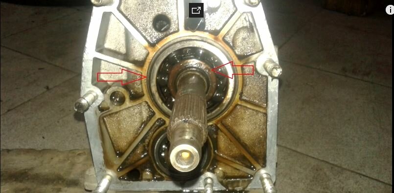

The bearing itself is difficult to remove here, so you cannot do without an assistant. Of course, you can get by with a puller here, but we did not have a suitable puller at hand. Therefore, we did it as follows:
- One held it with montages on both sides, as if pulling it out
- I knocked out the bearing by tapping through the copper lining on the input shaft.
In general, we collect everything and put it back in place in the reverse order. Well, that's how it is. There are still questions! Write them in the comments, if possible I will answer them.
Cars of the Niva family differ from VAZ cars by permanent all-wheel drive - they have two driving axles. In total, the transmission of the VAZ SUV has three differentials - one for each axle and another center differential.

The transfer case "Niva" is designed to distribute traction forces between the axles, and works on the principle of a 2-speed gearbox.
The distribution box is not present in all VAZ cars, but only on cars with two drive axles. In the transmission, the transfer case (RK) is installed at the rear of the gearbox; the rear propeller shaft is attached to its shank, which connects the transfer case to the rear axle. The front axle is also driven by the RK, it is connected to the transfer case by the front propeller shaft.
The reduction gear in the RK is designed to obtain high torque, it is used to overcome difficult road sections, helps to cope with off-road conditions. The VAZ Niva transfer case contains the following main parts:
- the body itself;
- front axle drive shaft;

- intermediate shaft;
- drive shaft;
- gears;
- bearings;
- differential housing;
- satellites;
- differential lock clutch;
- gear shift clutch;
- flanges (for connection with cardan shafts);
- oil seals;
- control levers.
The VAZ-21213 model is an off-road passenger car with permanent all-wheel drive and differential lock. Brand 21213 is a restyled version of the first VAZ SUV VAZ-2121. RK Niva 21213 has three gears:
- the first - with a gear ratio of 1.2;
- the second, reduced - with a number of 2.135;
- neutral.
21213 is equipped with 4-speed and 5-speed gearboxes, and when the first speed of the transfer case is on, the car works in standard mode, the gear ratios in the transmission are from 5-speed. The checkpoints are as follows:
When you turn on the second position of the transfer case lever (reverse position), the gear ratios change (decrease):
On normal roads, the first gear is constantly engaged on the transfer case, the transfer case control lever (reduction gear) is pushed forward. The neutral transmission of the RK disconnects the transmission, and in this position the car does not drive, there is also neutral in the checkpoint.
Often motorists ask the question - why do we need a neutral gear in the transfer case. Neutral is used when connecting additional units to the transmission, for example, a mechanical winch, in which case a power take-off must also be installed.
On Niva cars (with the exception of Chevrolet Niva), two main types of transfer cases are used:
- 21213 (modifications 21213-1800020-01 and 21213-1800020-02):
- 21214 (modifications 21214-1800020-01, 21214-1800020-02, 21214-1800020-10).
Between themselves, the transfer case has almost the same design - on the RK 21214 there is additionally a speed sensor drive.
The distributor of the VAZ 2123 car basically has the same device as the node 21213/21214, but the Chevy Niva has:
- different control mechanism (with one lever);
- an additional support is installed (on a simple Niva, the RK is mounted on two supports, on a VAZ 2123 car - on three supports).

The distribution box on the Niva is a fairly reliable unit, repair problems in the mechanism itself arise mainly due to the insufficient oil level in the RK - if for some reason the oil has leaked out, intensive wear of all parts occurs. Among the frequently occurring malfunctions are:
- vibration on the body at different speeds when driving a car;
- vibration at the moment of starting a car from a place;
- noise in the transfer case when the car is slipping or entering a turn;
- tight inclusion of a higher or lower gear, difficult engagement of the lock.
Vibration in the body is the main "disease" of the Niva, it often arises from the wrong centering of the transfer case. Most often, vibration occurs on VAZ 21213/21214 cars, since the RK is mounted only on two supports on the sides of the body, on the Chevrolet Niva the transfer case is already installed on three supports. But before you start adjusting the position of the transfer case, you should check the condition of other parts of the chassis - vibration may also occur for other reasons:
- cardan shafts are poorly fixed;
- wheels are not balanced;
- there is a backlash in the driveshaft crosspieces (especially the backlash in the rear driveshaft crosspieces affects vibration);
- vibration comes from the engine itself.
Vibration when starting off on the Niva can also occur for the following reasons:
- the fastening of the installation supports of the distributor was unrolled;
- the rubber on the RK supports themselves broke.
Correct installation of the transfer case can be done in several ways. Most often, in auto repair shops, repairmen use the following method:
- hang the car on a lift;
- weaken the fastening of the hand-out;
- start the engine;
- turn on the transmission and accelerate the car according to the speedometer to the speed at which vibration occurs (it often occurs at speeds from 40 to 80 km / h);
- without applying the brakes, they extinguish the speed with the engine, then turn off the ignition.
The distributor itself is centered in places, it remains only to tighten the fasteners of the supports.
You can also adjust the position of the RK using a wire, we do it as follows:
- we loosen all four fasteners of the razdatka supports;
- we fix one end of the wire to the rubber coupling of the propeller shaft;
- we also attach a piece of wire to the CV joint, bring the other ends of the wire to each other;
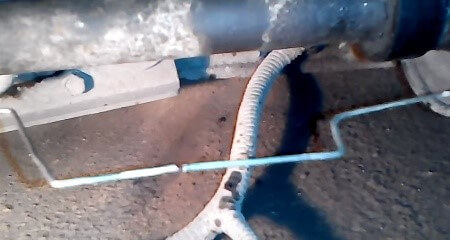
- we rotate the shaft, if the distributor is not centered, the ends of the wire will diverge during rotation;
- the task is to install the transfer case using the selection method so that the ends of the wire practically do not diverge from each other in any position when turning the shaft.
The installation of the third support of the RK on VAZ 21213/21214 cars allows to reduce the level of vibration of the transfer case, with this support it is easier to center the transfer case. The part can be purchased at auto dealerships or you can make it yourself. The finished product comes with three long studs (for model 2121); to install the third support on this machine, you will need to unscrew the short studs from the transfer case and install new studs from the kit.We make repairs as follows:
- dismantle the front passenger seat in the cabin;
- remove the lining of the floor tunnel;
- in the cabin, move aside the carpet covering the body amplifier (in front of the handbrake lever);
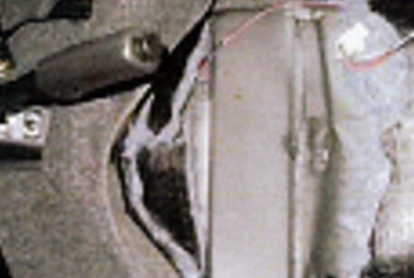
- we remove the transfer case (as an option, you can simply hang it out, but with the removal of the installation of the third support it is more convenient to do it);
- we attach a new support bracket to the RK body;
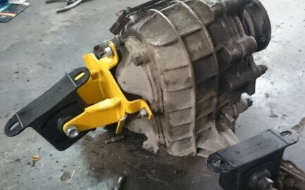
- install the transfer case in place, center it in the optimal position, attach the side supports;
- we combine the third support with the body, we drill two holes in the bottom;
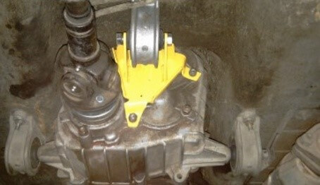
- using washers, bolts and nuts (included in the kit), we attach the support to the bottom of the body.
Vibration is more effectively eliminated by installing a stretcher under the dispenser. You can also make such a device yourself or buy a finished product at a car shop.
In order to install the subframe, the transfer case must be removed. It is more convenient to carry out such work in a pit, we carry out repairs as follows:
- we leave the car in neutral;
- we disconnect the driveshaft from the distributor, it is advisable to mark the flange of the driveshaft and the RK, so that during installation, install the driveshaft according to the marks - this way, the appearance of unnecessary vibrations is excluded;
- dismantle the muffler mounting bracket;
- remove the traverse of the checkpoint;
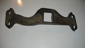
- jack up the distributor, remove the side mounts of the RK;
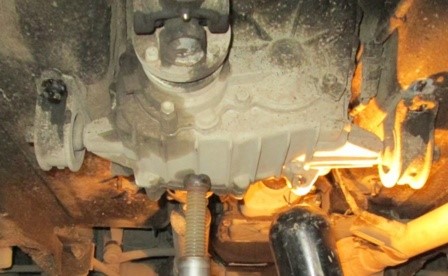
- we process the landing sites of the stretcher to the body with Movil;
- we put the stretcher on the gearbox studs;
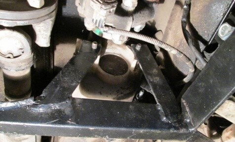
- mark the attachment points of the subframe on the side members, drill holes, bait the bolts on the body;
- we tighten all fasteners, except for the razdatka supports themselves;
- we make the alignment of the RK;
- finally tighten the transfer case supports.
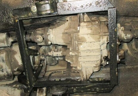
It should be noted that the installation of an additional support or subframe on the RK does not always lead to the desired effect, in some cases the vibration only increases.
To repair the transfer case on a VAZ 21213 (21214) car, the assembly must first be removed. Removal is performed in the following order:
- in the cabin we dismantle the plastic trim for the gearbox and gearbox levers;
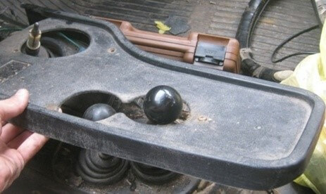
- we turn off the knobs of the transfer case shift levers, remove the casing under them;
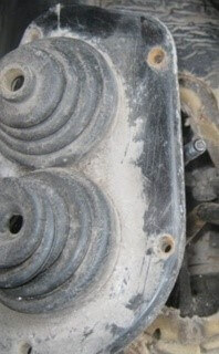
- we disconnect the speedometer cable, for RK 21214 it will be necessary to disconnect an additional speed sensor;
- we unfold the bolts with nuts securing the elastic coupling of the front and rear propeller shafts, in order to remove the bolts, the propeller shafts must be turned - they are removed one at a time in one specific shaft position;
- we install a jack (or other stop) under the distributor, mark the places where the side supports of the RK were attached. This is done in order to minimize the centering of the transfer case during installation;
- we unscrew 4 nuts securing the RK to the gearbox;
- unscrew 4 fasteners of the RK supports to the car body;
- now all that remains is to dismantle the transfer case.
NIVA CHEVROLET - repair of manual transmission and gearbox
Replacing oil seals in the razdatka and gearbox in the field
Installation of a modernized oil seal in the Republic of Kazakhstan on Niva 4x4
Changing the oil in the transfer case Niva Chevrolet
Chevrolet Niva transfer case repair
Why is the transfer case or box shank leaking?
Replacing the oil seal of the gearbox of the rear axle of the Chevrolet Niva
do-it-yourself oil seal replacement
Replacing the oil seals of the transfer case niva 2121


Greetings, dear friends! In today's article we will talk about repair, transfer case and gearbox on Niva Chevrolet. On the car, which we will carry out repairs, there were complaints from the owner about the presence of extraneous sounds in the car while driving. Increased vibration, hum, noise, and during the check it was revealed that the vibrations come from the transfer case of the car, the hum comes from the bearing of the input shaft in the gearbox. In general, now I will tell you how to fix these problems yourself.
We disassemble the transfer case for Chevrolet Niva change bearings and eliminate vibration - step by step instructions.
After we have replaced the bearing, we begin to assemble the transfer case.The assembly is carried out in the reverse order, but an important point: it is necessary to clean all adjacent surfaces from the old sealant and apply a new one to them .
Not complete disassembly of the gearbox on the Chevrolet Niva; we change the bearings and eliminate vibration - step by step instructions.
Now we proceed to incomplete disassembly of the gearbox on the Chevrolet Niva. In our case, only the bell needs to be removed. It rests on 5 nuts, so we unscrew them.


We immediately draw attention to the fact that the oil seal ran here, therefore, it is necessary to replace it.


Here is a photo of the input shaft bearing. Remove the stoppers from the outer and inner sides of the bearing race.


The bearing itself is difficult to remove here, so you cannot do without an assistant. Of course, you can get by with a puller here, but we did not have a suitable puller at hand. Therefore, we did it as follows:
- One held it with montages on both sides, as if pulling it out
- I knocked out the bearing by tapping through the copper lining on the input shaft.
In general, we collect everything and put it back in place in the reverse order. Well, that's how it is. There are still questions! Write them in the comments, if possible I will answer them.
You will need: keys "10", "13", "17", "24", "27", screwdriver, circlip remover, bearing remover, tweezers, punch, chisel, vice with soft metal jaws ...
1. Drain the oil from the transfer case (see "5.3.2 Changing the oil in the transfer case") and remove it from the vehicle (see "5.3.7 Removing and installing the transfer case").
2. Use a screwdriver to pry the locking sleeve and remove the gearbox control lever rod.
3. If the spacer and rubber ring are worn, remove them from the arm by prying apart the spacer tabs.
4. To reinstall the lever rod, install the spacer, locking sleeve and rubber ring into the lever rod in the reverse order of removal.
5. Remove the retaining ring and pull out the control arm shaft.
6. Remove the yoke axle bolt and ..
7.. remove the control mechanism.
8. Check and if necessary replace the plastic bushings of the lever, clean and grease all joints of the mechanism.
9. Remove the differential lock warning lamp switch from the transfer case housing.
10. Remove the nuts securing the control arm bracket and.
12. Unscrew the nut securing the fork in the bracket and.
thirteen. . disassemble the bracket. Replace worn or damaged parts.
14. Remove the nuts securing the side cover.
15. . remove the cover and the gasket underneath.
NOTE
Replace a heavily crimped or torn gasket by lubricating it with a thin layer of sealant on both sides before installing.
16. Loosen the nut securing the shift clutch fork.
17. Using a screwdriver, remove the plug of the hole for the gear selector rod from the box crankcase.
18. Rotate the rod around its axis and smoothly slide it out of the crankcase until the lock ball appears. Use tweezers to remove the ball and.
WARNING
Pull the stem very carefully, as the ball of the retainer is spring-loaded and can suddenly fly out of the stem seat.
20. Remove the stem from the crankcase by alternately removing the plug and from it.
22. Finally remove the stem.
23. Replace the stem O-ring if necessary.
24. Unscrew the nuts of the front axle drive housing cover and remove it.
25. Remove the differential lock rod retainer spring.
26. Remove the differential lock fork retaining bolt.
27. Take the protective cover of the stem away from the crankcase and,
28.. while extending the stem, tilt the transfer case forward so that the ball of the retainer rolls into the front axle drive housing. Having finally removed the stem, remove the plug from it, and then remove the ball from the crankcase.
29. Replace the stem O-ring if necessary.
30. Remove the five nuts securing the front axle drive housing.
31.. use a screwdriver to separate it from the transfer case housing and.
33.Remove the differential lock clutch.
34. Remove the gasket or remove its remnants.
35. Disassemble the front axle drive, for which fix the shaft in a vice with soft jaws, unscrew the self-locking nut of the front axle drive flange and remove the washer installed under it.
WARNING
Self-locking nuts must not be reused, replace them with new ones!
37. Using a puller, remove the retaining ring and.
38. remove the shaft from the crankcase assembly with the bearing.
39. Remove the oil baffle and thrust rings from the shaft. Further disassembly of the shaft is described below.
40. Unscrew the nuts securing the bracket to the transfer case housing, and then the rest of the nuts securing the rear cover of the box.
41. Use a screwdriver to separate the rear cover from the box crankcase and.
42.. remove the cover together with the rear axle drive shaft.
43. To disassemble the rear cover, fix the shaft in a vice with soft jaws and unscrew the self-locking flange nut.
WARNING
Self-locking nuts must not be reused, replace them with new ones!
44. Remove the nut, washer and flange.
45. Remove the retaining ring from the inside of the cover and.
46.. remove the shaft assembly with the bearing from the cover.
47. Remove the oil baffle and thrust rings from the shaft.
48. Remove the speed sensor drive (see "5.3.4 Replacing the speed sensor drive").
49. Unscrew the self-locking nut of the intermediate shaft mounting flange.
WARNING
Self-locking nuts must not be reused, replace them with new ones!
50. Remove the nut, washer and flange.
51. Using a puller, remove the drive shaft rear bearing retaining ring.
52. Unscrew the nuts securing the front bearing cap of the drive shaft and.
54. Unscrew the remaining nuts securing the rear cover of the transfer case housing and.
56. Remove the differential from the box case.
57. Remove the drive bearing retaining rings and.
59. Remove the intermediate and from the crankcase.
61. To disassemble the differential, remove the retaining ring from the differential shaft.
63. Press the bearings off the differential housing trunnions using a puller.
64. Make marks on the separable parts of the differential housing so as not to disturb their mutual balance and alignment.
65. Remove the differential housing pinch bolts.
67.. remove the driven gear.
69.. separate the front and rear differential housings.
70. Remove the half-shaft gear from the front housing.
71. Remove the pinion shaft retaining ring.
73.. remove the pinion shaft from the holes in the rear housing.
74. Remove the satellites and from the rear housing.
75.. the second gear of the axle shaft.
76. Install the removed parts and assemble the differential in the reverse order.
77. If necessary, disassemble the intermediate shaft. Remove the outer race of the front intermediate shaft bearing.
78. Using a screwdriver, carefully, without damaging the separator, squeeze the rollers and out of the separator.
80. Using a spacer (socket head) of a suitable diameter, install the puller so as not to damage the gear wheel of the speedometer drive mechanism, press the inner ring of the bearing and from the shaft.
82. To remove the rear bearing, unscrew the nut, remove it together with the washer and.
83.. press the bearing with a puller.
84. Assemble the intermediate shaft in the reverse order of removal. After tightening with the required torque, lock the bearing retaining nut with a bit, pressing the nut collar into the shaft groove.
85. To disassemble the drive shaft, unscrew the bearing retaining nut and remove it.
87. Using a puller, remove the bearing from the shaft.
88.. thrust ring and low gear.
89. Remove the transfer clutch together with the hub and.
90.. top gear.
91. Using a puller, remove the bearing from the shaft.
92. Assemble the drive shaft in the reverse order of removal.After tightening the bearing retaining nut with the required torque (see Appendix 1: Tightening torques for threaded connections), lock it with a bit.
93. Assemble the transfer case in the reverse order of disassembly.
NOTE
Press the bearings onto the shafts using a mandrel, applying force only to the inner race of the bearing. When pressing the bearing into the housing (crankcase), apply force only to the outer race.
WARNING
Self-locking nuts must not be reused, replace them with new ones! Replace all removed gaskets with new ones.
USEFUL ADVICE
Even install new gaskets with sealant.
In order to change the amount of torque and distribute it between the rear and front axles, the Chevrolet Niva has a transfer case, which has two gears. These two axles are connected to each other by an interaxle differential, which divides the torque equally, and in order to increase the cross-country ability, the differential is locked, while the drive shafts are rigidly connected to each other.
Therefore, it is very important to know what a Chevrolet Niva handout device is, which it is also desirable for the owner of this SUV to know.

- This device is fixed on several brackets to the floor of the car body. The parts in the box are made of aluminum alloy, which are interconnected with nuts and studs.
- The upper part of the crankcase is equipped with a special hatch, which is closed by a steel cover. There are cardboard spacers in the space between the crankcase and the lid.
- All shafts in it are sealed with cuffs, which are made of rubber-metal material. Also, rubber rings sealed such elements as: Differential lock, shift fork rod, speed sensor, as well as drive shaft
- A drive shaft is mounted on a pair of ball bearings, and the outer rings are located in the crankcase and in the slots of the front cover.
If you read the regulations, it is recommended to change the oil in the transfer case every forty-five thousand kilometers. The following tools are required for replacement:
- Key for twelve
- Syringe
- Capacity where you can drain the mining
After the tool is ready, we proceed to the replacement:
- We unscrew the oil drain plug and drain the working off
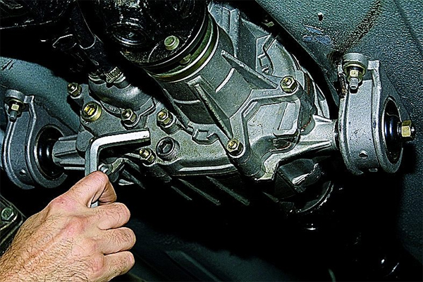
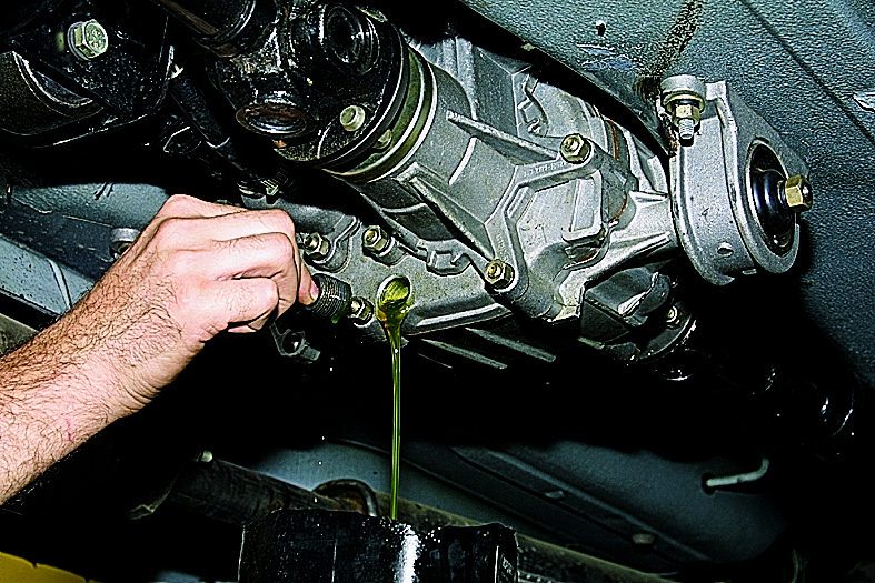
- We twist the drain plug back, and unscrew the filler
- Fill with a syringe with new oil to the desired level, at this point the process can be considered complete.
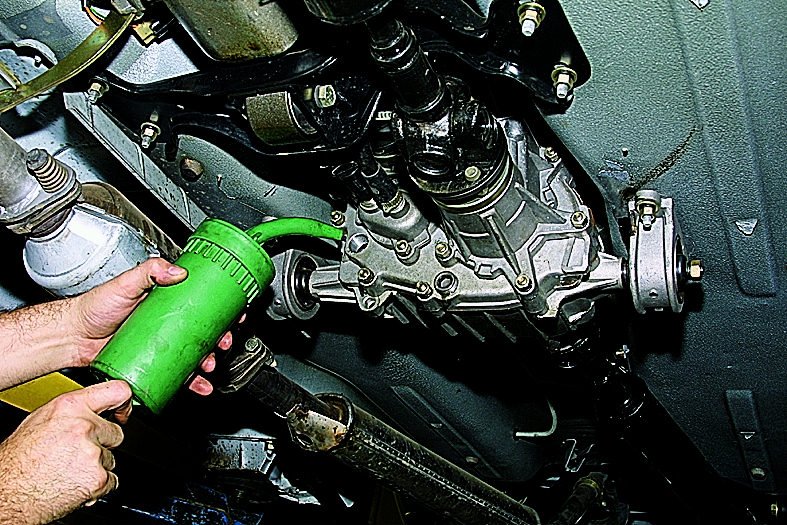
Sometimes it is necessary to replace the transfer case on a Chevrolet Niva car, and in order to do this, it should be dismantled, for this it is necessary to do the following:
- We take two keys for thirteen and seventeen, and disconnect the driveshafts from it
- Disconnect from the transfer case from the passenger compartment, cover with handle
- We remove the cover of the lever, which is responsible for switching the drive
- For the existing box suspension, loosen the fasteners
- Disconnect all wires from the lamp responsible for the differential lock
- We install a support under the box, unscrew all the nuts that secure the pillow, and remove the distributor
In order for it to fall into place, you should do all the steps in the reverse order.
The transfer case works very noisy, probably every owner of the Niva is faced with this problem, this noise is transmitted to the salon through the levers in it. There are two ways to get rid of this howling.
- You can buy special silent levers for a Niva handout, from which they are suitable, and will cost around 3,000 rubles.
- You can make it yourself, while spending much less.
In order to make them yourself, you can take:
- Lever repair kit from GAZ 31105 from a five-speed gearbox
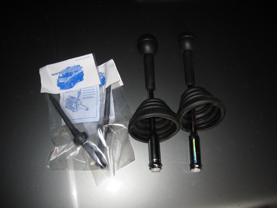
- Two levers from VAZ
- Standard lever
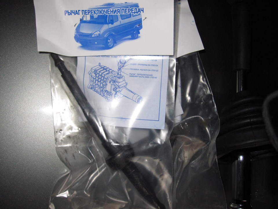
With the help of a grinder, you need to cut off all the elements to the desired level, and then use a welding machine to weld it all. In time, it takes about two hours.The essence of this device is that due to rubber and plastic bushings, which are located on the lever of the box, noise and vibration are damped. Let's consider the whole principle with an example:
- Removing the lever
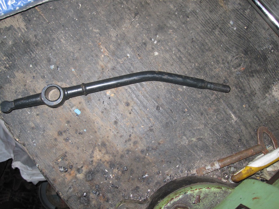
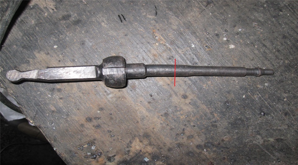
- We cut to the size we need, as in the pictures
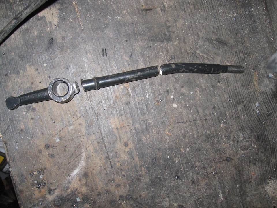
- The lever that changes gears is cut one centimeter above the narrowing
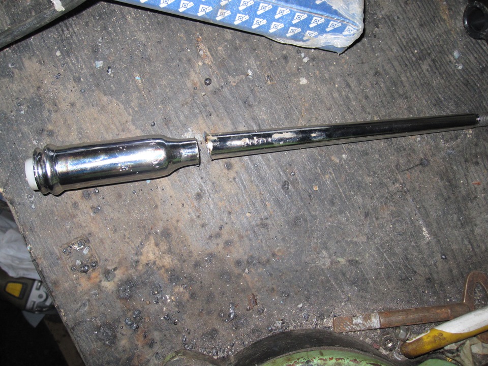
- Saw the lever from the GAS below the thickening by one and a half centimeters
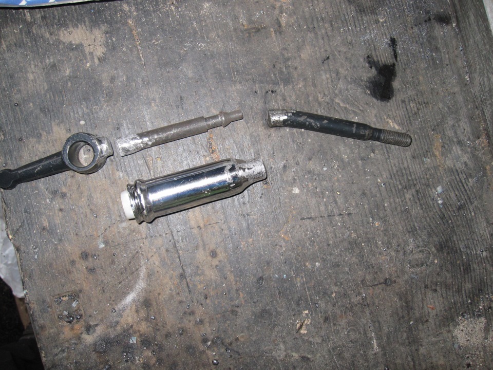
- We put the resulting elements we need together.
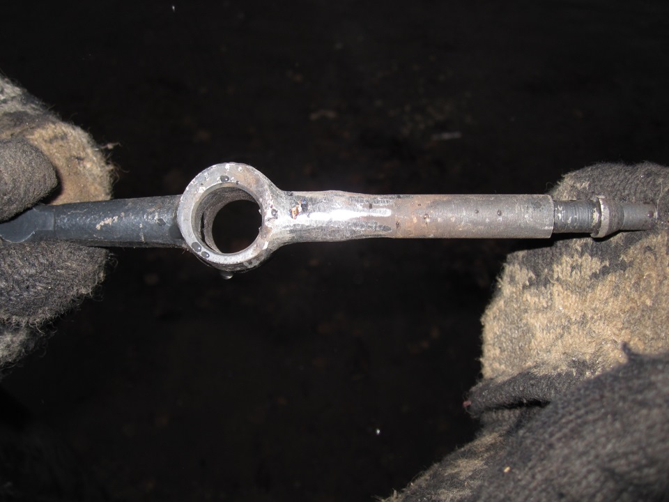
- Then we weld the native lever and the lever from the GAS together
- On the welded part that turned out, we put on the existing part from the KP
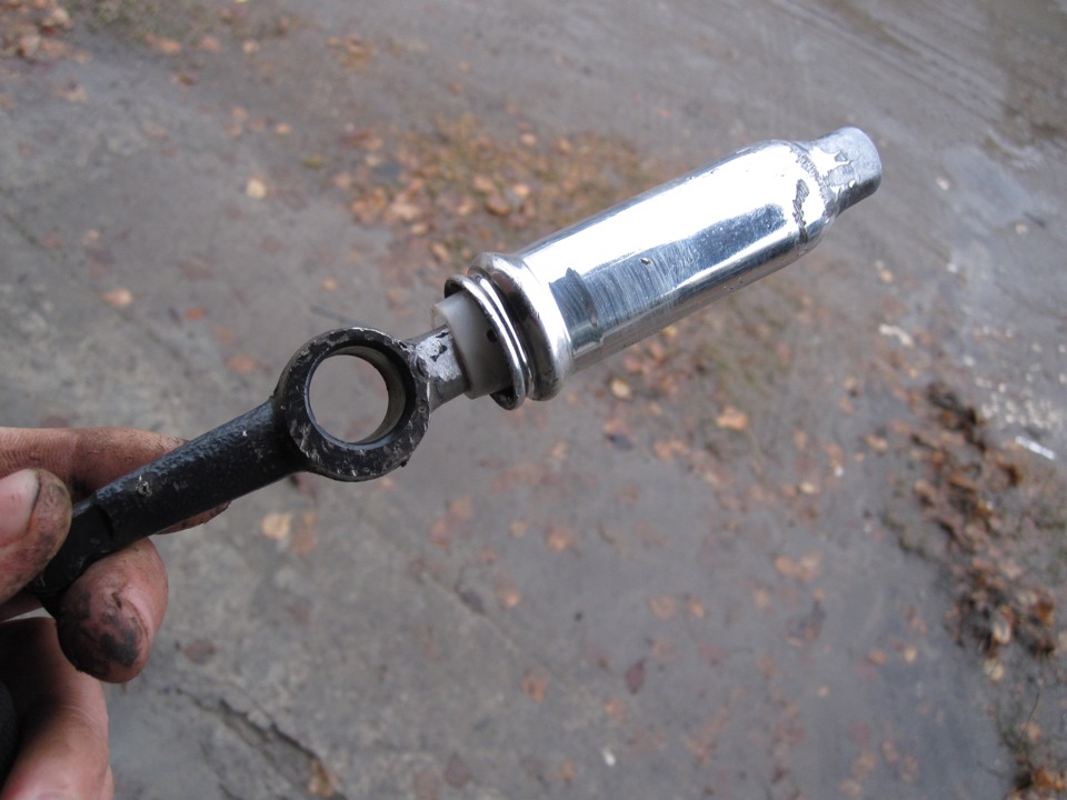
- We weld the upper part of the existing native lever as needed
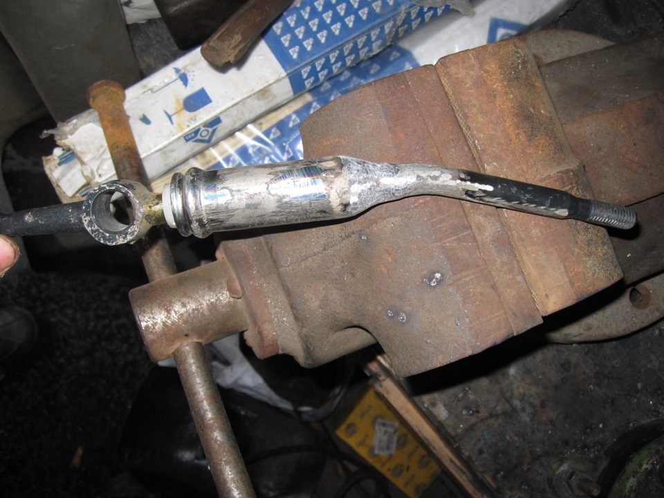
- We get the design we need
- We prime and paint the resulting elements
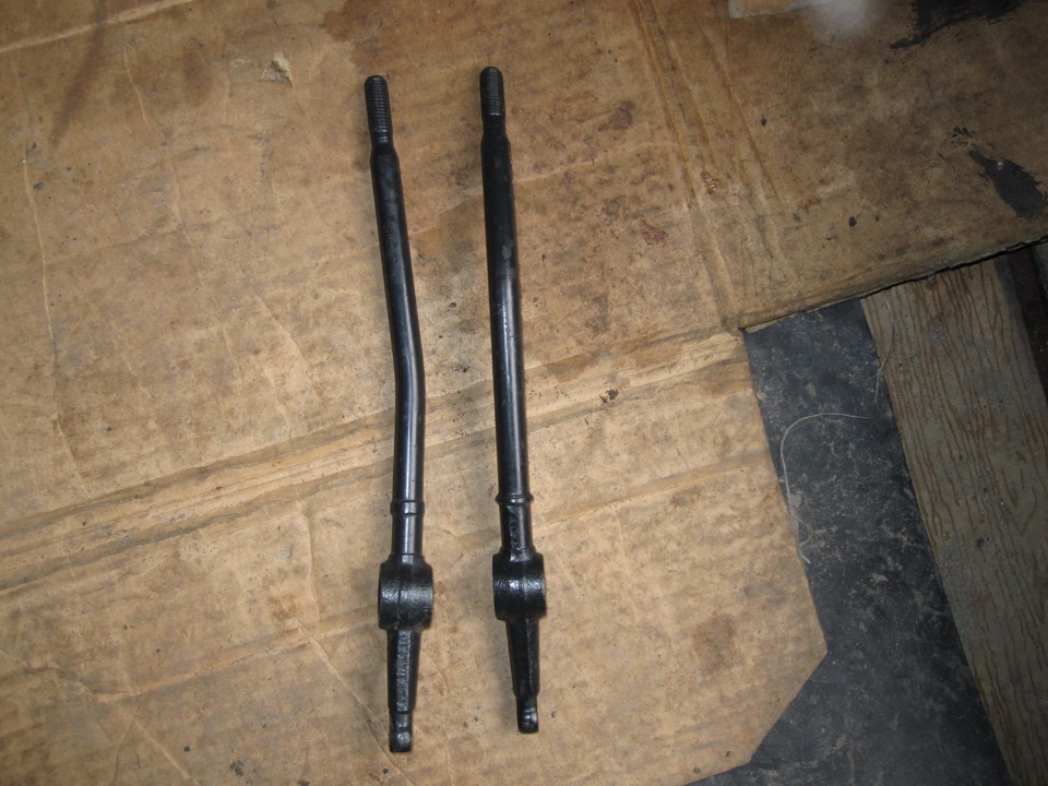
- We cut the upper part of the sealing gum, low and high gear
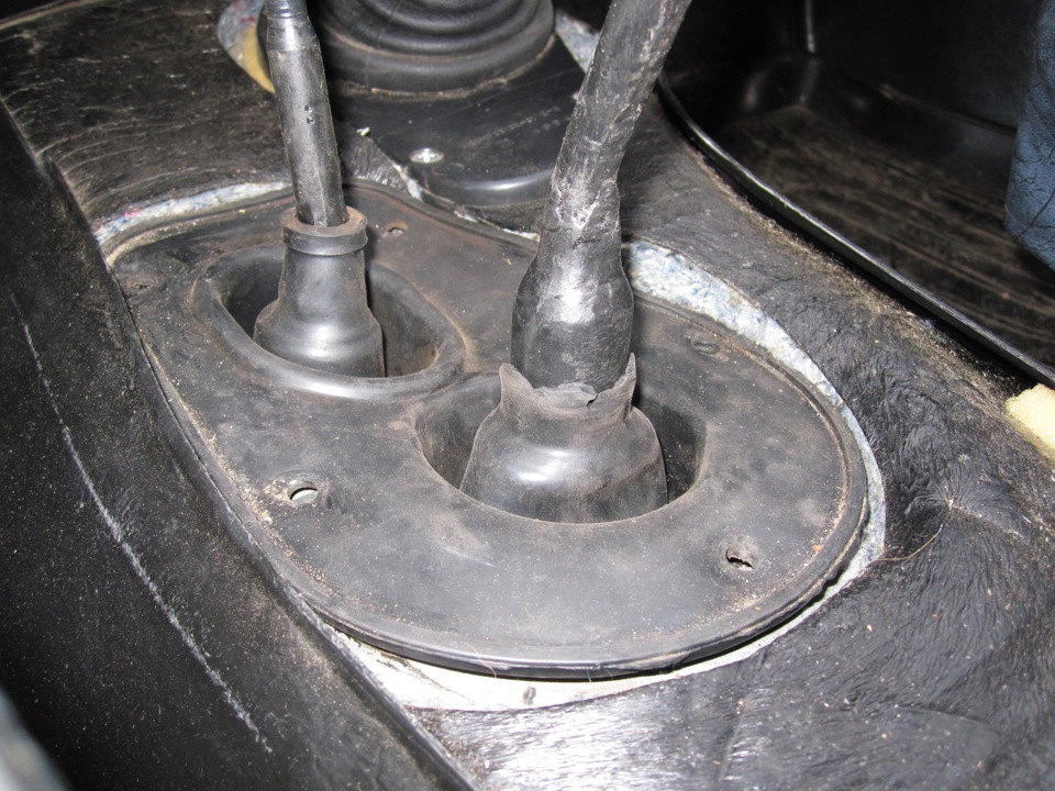
If everything is done correctly, they are almost indistinguishable from gratifying. As a result of the actions taken, we get that the inclusion is softer than it was, vibration practically disappears, strong noise disappears, and most importantly, you can do this yourself while saving money.
Transfer case overhaul - general information
Overhaul of the transfer case is a difficult procedure to perform on your own. It involves the disassembly and correct reassembly of many small assemblies and components. It is necessary to accurately measure the many gaps and correct them correctly by choosing the appropriate size shims and circlip. Thus, if it becomes necessary to overhaul the transfer case, its removal and installation can be performed by an amateur mechanic, while the actual repair and restoration should be left to the car service specialists. There is a possibility of purchasing remanufactured boxes - consult the specialists of the dealer department. In any case, the time and money spent on repairing and restoring the old box will turn out to be quite commensurate with the cost of purchasing a restored unit.
Nevertheless, it should be said that the overhaul of the transfer case by the forces of even an inexperienced amateur mechanic is quite possible, provided that there is an appropriate special tool and an accurate and careful approach to performing each of the procedures, when not even the smallest steps are skipped.
Tools required to perform a transfer case overhaul include pliers for removing and installing both inner and outer circlips, bearing puller, sliding hammer, drift set, plunger-type dial indicator, and possibly a hydraulic press. In addition, a strong, comfortable-height workbench equipped with a vice, or a stand for dismantling transmissions, is absolutely essential.
When disassembling the transfer case, pay close attention to how each of the smallest components are installed, their position in relation to other parts, and the type of fasteners (take notes as you disassemble). The accompanying illustrations provided here are intended to help you understand the layout of the box - however, drawing up explanatory notes during disassembly still much more reliably guarantees the correctness of subsequent assembly.
Transfer case components type NP231
1 - Front holder of the cross, its oil seal, sealing washer and fastening nut
2 - Plug, pin and spring of the switch lock
3 - the Front holder with an oil seal
4 - the Front half of the crankcase
5 - Vacuum sensor-switch with a sealing ring
6 - Assembly of the ventilation line
7 - Bearing and retaining ring of the primary gear
8 - the Retaining ring of a gear wheel of a reduction gear
9 - the holder of the primary gear
10 - Thrust washers of a gear wheel of a reduction transfer
11 - the Primary gear wheel
12 - the Guide bearing of the primary gear
13 - the Gear wheel of the lowering transfer
14 - a hub of a fork of switching of modes
15 - the Retaining ring of the hub
16 - the Distance washer
17 - the Springs of the synchronizer
18 - Sliding keys of the synchronizer
19 - the Hub
20 - the Coupling
21 - the Blocking ring
22 - Retaining ring of the front bearing
23 - the Front bearing of a secondary shaft
24 - the Front secondary shaft
25 - the Drive sprocket
26 - Drive chain
27 - Bearings of the drive sprocket
28 - Rear bearing of a secondary shaft
29 - the Driven shaft
30 - the Epiploon
31 - Assembling the oil pump
32 - Rear bearing of a driven shaft
33 - the Lock ring
34 - Rear half of the crankcase
35 - Filling plug with a gasket
36 - Drain plug with a gasket
37 - the Back holder
38 - Extension casing
39 - the Bushing
40 - the Epiploon
41 - the Mesh screen of the oil sampling tube
42 - Nipple connection of a tube
43 - Oil intake pipe
44 - the Sealing ring of the oil sampling tube
45 - Magnet
46 - Nut and washer of the lever of modes
47 - the Lever of modes
48 - the O-ring and the bushing of the holder of the selector
49 - Selector
50 - Fork modes
51 - Range plug
52 - Spring modes
Transfer case components, type NP242
1 - the holder of the front bearing with an epiploon
2 - the front half of the crankcase
3 - Switching selector
4 - a Fork of switching to a lower gear with inserts
5 - the Shift rod
6 - the Shifting bracket
7 - the Slider bracket
8 - the Bushing with a spring
9 - Fork of modes with inserts
10 - Bushing
11 - the spring of a fork
12 - the Bushing
13 - Assembly of the ventilation line
14 - Bearing and retaining ring of the primary gear
15 - Retaining ring of a gear wheel of a reduction gear
16 - the Holder of a gear wheel of a reduction transfer
17 - the Thrust washer of the gear of the underdrive
18 - the Primary gear wheel
19 - the Rear half of the crankcase
20 - Drain and filler plug
21 - the Rear bearing holder
22 - Extension casing
23 - the Bushing and the epiploon
24 - the Vacuum sensor-switch
25 - Magnet
26 - the Thrust ring
27 - the Lock ring
28 - the switching clutch
29 - the Gear wheel of the lowering transfer
30 - Guide bearing (primary gear / driven shaft)
31 - Front bearing of the front output shaft and circlip
32 - Shaft of intermediate clutch
33 - the switching clutch
34 - the Lock ring
35 - the Driven shaft
36 - Assembling the differential
37 - the O-ring of a tube of the oil pump
38 - Oil intake pipe of the oil pump with a mesh screen
39 - Rollers of the bearing of the driven shaft
40 - the Drive sprocket
41 - Drive chain
42 - the Lock ring
43 - the Oil pump seal
44 - the Oil pump
45 - Rear bearing with a circlip
46 - Rear bearing of the front output shaft
47 - the Lock ring
48 - Driven sprocket
49 - the Front secondary shaft
50 - Spacer washers of the driven shaft bearing
51 - Washer and nut of the shift lever
52 - the Lever of switching
53 - O-ring and sector oil seal
54 - Cork, spring and retainer pin
55 - the Sealing plug
56 - The front holder of the cross with a nut and a sealing washer, a slider and an oil seal
Transfer case components, type NP249
1 - the Epiploon
2 - the holder of the front bearing
3 - The front bearing of the driven shaft with a locating ring
4 - The front half of the crankcase (with a toothed ring of the underdrive of internal gearing and a bushing of the shift rod)
5 - the gear wheel of the lowering transfer
6 - the Primary gear wheel
7 - Thrust washers equipped with tongues
8 - Holder plate
9 - the retaining ring of the primary gear
10 - the clutch
11 - Clutch shaft
12 - the locking ring of the differential
13 - Differential assembly
14 - the Driving gear wheel of the driven shaft
15 - Retaining ring of a driving gear
16 - the Spacer washer of the driven shaft bearing
17 - Needle bearings of the driven shaft
18 - the Spacer washer of the driven shaft bearing
19 - the Driven shaft
20 - Viscous clutch
21 - the Retaining ring of the viscous clutch
22 - the Retaining ring of the oil pump installation
23 - the Oil pump
24 - Rear bearing of a driven shaft
25 - Retaining ring of the rear bearing
26 - the Drive gear wheel of the speedometer
27 - Assembling the rear holder (with a cap, an oil seal, a bushing, an access cover and a gasket)
28 - a locating ring of the rear bearing
29 - the Front half of the crankcase
30 - Rear bearing of the front output shaft
31 - Assembling the oil suction tube (with connecting hoses, mesh screen, tubes and O-ring)
32 - Assembling the shift fork with the rod (including fork lining)
33 - Drive chain
34 - the Front secondary shaft
35 - the Switching selector
36 - the crankcase magnet
37 - Front bearing of the front output shaft
38 - Retaining ring of the bearing
39 - Plunger and retainer spring
40 - Plug and retainer O-ring
41 - Lock nut and washer of the mode lever
42 - the Lever of modes
43 - Oil seal (front bearing of the front output shaft)
44 - the Holder of the secondary shaft cross
45 - the Sealing washer of the holder of the cross
46 - the Nut of the holder of the cross
| Video (click to play). |
Before sending the transfer case for repair, it is helpful to have an idea of which part of the transfer case is causing the problem. Some of the defects are uniquely associated with different nodes, which can greatly simplify the troubleshooting procedure and reduce the time for troubleshooting. See also Section Troubleshooting at the beginning of the Guide.


