In detail: do-it-yourself repair of a dre 7300 receiver from a real master for the site my.housecope.com.
This video examines a typical defect in receivers DRE-5000, 5100, 7300, etc., used to view satellite programs.
The defect manifests itself in these receivers in the form of a constant blinking of the indicator on the front panel of the receiver.
The culprit is mainly the power supply, or rather electrolytic capacitors in the secondary circuits of the power buses.
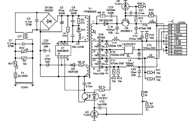
When checking with an ESR device, one of the litas C17_1000.0 μF-10 volts seemed a little suspicious, although the capacitance was not dry.
Yes, for the ESR check, the deviations are not so large, you can see everything in the video.
Initially, I did not change it, I considered this moment not so important, but started with the DM0365R power supply and so on along the chain (judging by the client's story).
Having spent a lot of time looking for a defect, I decided to change the dubious C17_1000.0 uF-10 volts, so .. just in case.
It turned out, not in vain, hit the mark. Now turn on and enjoy.
Another point about the defect, only now visible to the eye.
The malfunction is one-to-one, only you can see the problem with the naked eye, just look at it once ...
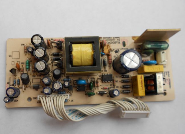
We are really looking at the same lick, only already swollen.
Another typical defect with the next DRE-5100 receiver.
According to the client, if you turn it off from the network and turn it on again, the indicator starts blinking and after a while the receiver turns on, and the last time it waited for 2 hours, but not at all.
Again, we are looking at the receiver's power supply module, or rather, at the appearance of the lithics.
Two faces are clearly visible here, the culprits in the problem.
If you have any questions, watch the video below.
| Video (click to play). |
Is registered: 24.09.
Posts: 5
Location: Kashira
I would like to learn more in this thread about all the "jambs" mentioned in the title of the topic of the receiver and how to solve them.
I have the following problem with this piece of iron (by the way, this problem occurs on different forums):
We turn on, set up, activate, look for channels, watch, rejoice, and then at some point bam and our FRIEND hangs.
Reboot, enjoy and. Bam
Friends, advise how to eliminate THIS BAM and write about your troubles with this GS.
Thanks in advance to everyone
Is registered: 18.08.2007
Posts: 400
Location: Bryansk
Is registered: 24.09.
Posts: 5
Location: Kashira
Is registered: 18.08.2007
Posts: 400
Location: Bryansk
Is registered: 24.09.
Posts: 5
Location: Kashira
The problem appeared again and was solved by flashing the software.
By the way, levalentino, do you repair (solder) the receivers yourself?
I haven’t dealt with this matter yet. Basically, TVs, radio tape recorders, amplifiers and everything that neighbors and friends bring home from work. I can give advice on a beautiful inconspicuous soldering. There are such hot air guns, soldering irons, which are used mainly for repairing cell phones. You can try them. I (took from a friend) M / s on the memory lines for the computer soldered. It turned out like a factory.
And so as not to wash my hands and do not blast with static, I have a special bracelet with a wire and a crocodile, though I never used it.
And thank you for the advice. Bryansk-1 hello
Is registered: 18.08.2007
Posts: 400
Location: Bryansk
GROMOZEKA
mine
Is registered: 23.12.2006
Posts: 27
Location: Komi Republic
The main and most common malfunction of all receivers is a malfunction in the power supply and voltage conversion circuit. Also, the modulator often fails due to a short circuit in the coaxial cable from the LNB, although the latest models have good protection against short circuits in the cable, when triggered, the voltage supply to the converter simply stops until the short circuit is eliminated.
And so, our receiver does not show any signs of life, the indicators on the front panel display do not light up, and no twitching of the power plug from the outlet and turning on the toggle switch does not help us (at least that was the case with the device, an example of which is given in this article) ... The first thing we do is pull out the plug from the network and remove the top cover, we need to get to the electronic filling of the device. And here it is important to remember one thing, namely about the warranty seal, which we will of course break if we remove the cover. Therefore, once again make sure that the warranty period has definitely expired, and under warranty no one will repair it for you. If the warranty is still valid, I advise you to take the receiver to a service center and entrust this matter to a specialist.
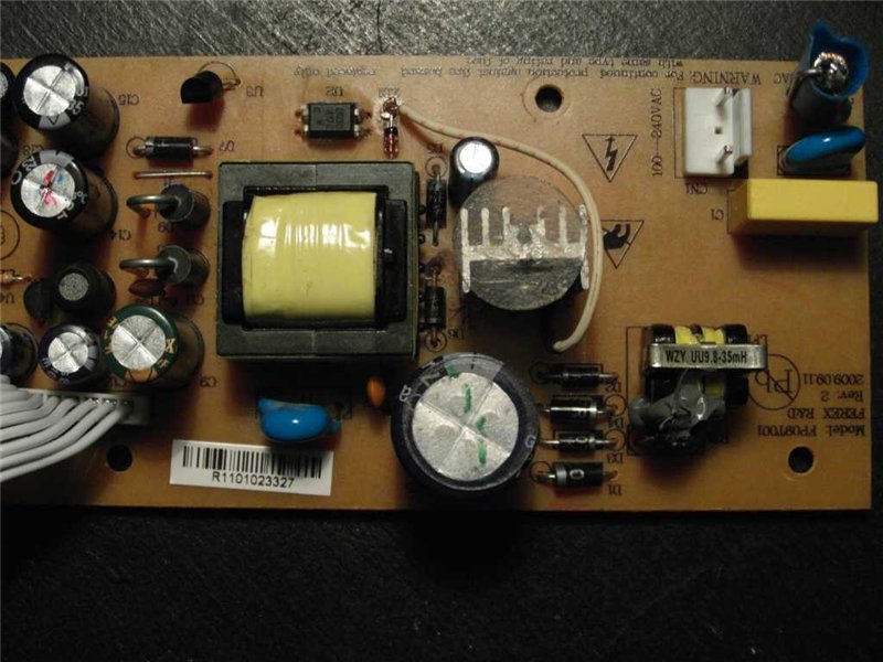
Receiver inside:
The electrolytic or oxide capacitor at the input often dries up and fails, which is also a malfunction, not everyone can find such a breakdown either, you need to have at least an initial level of a radio amateur. Usually, defective capacitors are swollen, yellowish, or have a small brown speck on the board at the base of the legs. Also, the serviceability of a capacitor can be determined by comparing its nominal and measured capacitance.
The receiver uses direct current, which is rectified from the AC mains using a diode bridge. Problems with the diode bridge also happen. It is very simple to check diodes, the main function of a semiconductor diode is to pass current in one direction, and not in the other. In my case, the transistor of the primary winding of the transformer turned out to be faulty, it is not difficult to find it, it usually has a radiator to remove heat. I determined the malfunction of the transistor by measuring the voltage at its emitter, it was absent there, the primary winding was not powered, respectively, everything else is de-energized. The transistor cost me 28.5 rubles. Replacing it with a soldering iron, I eliminated the malfunction and the receiver is back in working order. I must say such a breakdown is quite a rare occurrence, usually it all ends with a fuse.
A very common malfunction is a firmware crash. The firmware often crashes, this is usually evidenced by the complete hang of the receiver. In this case, "flashing" will help. I will say about one more reason for the malfunction, which may arise due to poor-quality installation. Water in the cable. If the outer insulation of the cable is broken, then water from atmospheric precipitation can get inside, it easily enters the receiver like a hose, sometimes flooding all of its insides. The condition of the cable must be monitored throughout the entire service life of the device.
lihanovich »22 Jul 2009, 17:07
Repair of receivers DRE4000,5000,5001,7300 FTA 7001,7101, VA-7200. and others
The procedure for resetting the PIN code for different models of Tricolor receivers
For models DRE-4000, DRE-4500, DRE-5000, DRE-5500, DRE-7300, DRS-4500, DRS-5001, DRS-5003, GS-7300
1) Install software (hereinafter referred to as software) version 2.0.91;
2) in the "Status" menu, sequentially dial the key combination on the remote control (hereinafter referred to as the remote control): white button (clock), 9, yellow button, 4, red button, 8, 7, 3, 5, green button;
3) confirm the change of the PIN-code;
4) check the ability to access the "Settings" menu using the PIN code "0000".
For DRS-8300, GS-8300 (M / N), GS-8302 (S)
1) in the "Status" menu, sequentially dial the key combination on the remote control: white button (clock), button "9", yellow button, "4", red button, "8", "7", "3", "5 ", Green button.
2) confirm the change of the PIN-code;
3) check the ability to access the "Settings" menu using the PIN code "0000".
one more code for GS-8300
White_button_ (clock) -> 9 -> Yellow_button -> 4 -> 1 -> 8 -> 7 -> 3 -> 5 -> EPG
For the GS-8304 model, the following sequence of actions allows you to reset the PIN code to "0000":
1) turn off the power supply of the receiver;
2) press and hold down the buttons "P +" and "P-" (buttons for switching programs) on the front panel of the receiver;
3) turn on the power supply of the receiver;
4) check the ability to access the "Settings" menu using the PIN code "1111".
For the GS-8304 model, the following sequence of actions allows you to reset the PIN code to "1111":
1) in the main menu, sequentially dial the key combination on the remote control: red button, yellow button (2 times), red button;
2) confirm the change of the PIN-code;
3) check the ability to access the "Settings" menu using the PIN code "1111".
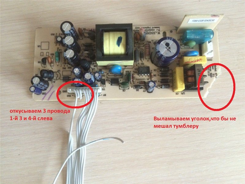
the cap had to be removed, who needs it in the forum he will find about the repair of the power supply. if you write something in a personal, what I can, so I will help
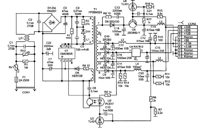
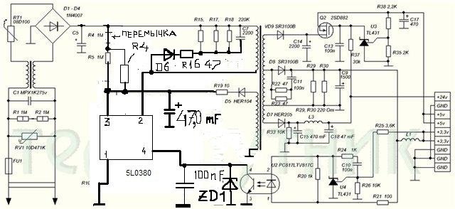
PSU DRE4000]
power supply circuit 8300
if the temka komuta helped, I will take it from you +
How regulation works. The stabilization of secondary voltages occurs using a feedback circuit, the reference diode U3 of the parallel stabilizer together with the emitting diode and the transistor of the optocoupler U2, which also provides galvanic isolation between the primary and secondary circuits, controls the operation of the PWM generator of the controller U1. With an increase in the output voltage between terminals 1 and 2 of U3, the current through it and the emitting diode of the optocoupler increases, which leads to the opening of the optocoupler transistor, at the controlled output Vfb of the PWM controller there will be a low level and the modulator reduces the duration of the control pulses of the output transistor at the output of the microcircuit U1, the energy transferred in
the secondary circuits will decrease, respectively, the output voltages will decrease, when the voltage becomes below normal, the current through U3 and the optocoupler diode will decrease, which will entail the closing of the optocoupler transistor and an increase in pulses on the output transistor, the energy transferred to the secondary circuits will increase, respectively, the output voltage of the power source will increase.
1. Access to viewing is denied (error 2).
Cause: The receiver cannot read the smart card.
2. No access to view: (error 3), (error 13)
Reason: Scrambled channel. Leave the receiver to decode (8 hours)
3. No access to viewing. TV / radio channel is not broadcasting "Tricolor TV" (error 4).
Cause: The TV / radio channel is broadcast in an unsupported coding (channel from another satellite TV provider).
4. The smart card is not recognized by the receiver. Make sure the smart card is inserted correctly (error 5).
Cause: Incorrect smart card or smart card inserted incorrectly.
5. No access to view (error 7).
Cause: The smart card does not belong to the operator.
6.No view access. Please make sure that the registration is completed or the subscription with the selected TV / radio channel is paid and active. (error 9).
Cause: There are no subscription classes in receiver memory.
7. No access to viewing. To resume viewing, you must pay for the service (service name). Learn about the payment methods in the receiver's menu "How to pay" (error 10).
Cause: You do not have a subscription to the main service.
Written by Administrator on December 12, 2011.
repair article DRE_4000 (ps Not the same as in the 1st post)! Most of the questions will disappear by themselves after studying. Inside there are diagrams: a power supply unit, an STi5518 processor unit, a Z-Crypt decoder.
repair article DRE 5000.
Inside article_DRE_5000 schematic: power supply, channel selector interface fragment.
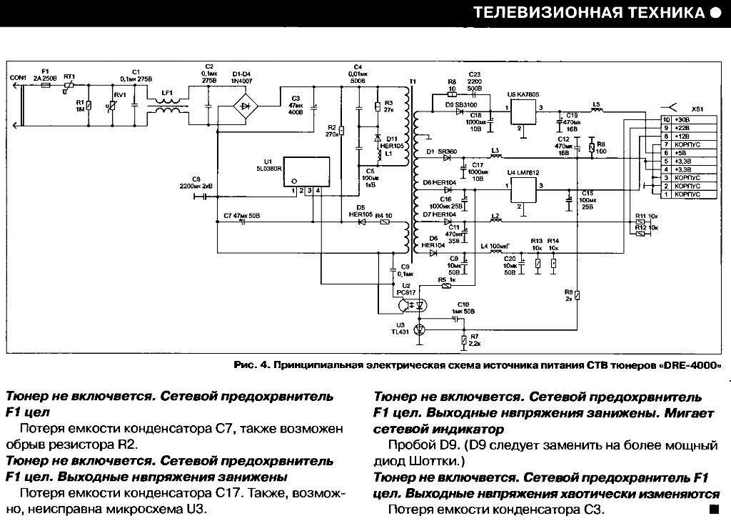
article on the device and repair of power supplies some receivers. Inside the article of the circuit: "HUMAX F1 / CI / VA / VACI", "Strong SRT4450", "Sky Way 6000", "DRE-4000" (as well as characteristic defects of the power supply "DRE-4000" and ways to eliminate them )
article on restoring and updating the receiver software using RS-232 (COM) and JTAG, using the example of DRE_4000,5000.
Inside COM wiring diagram, 2 JTAG options (wiring and wiring diagram)
DRE-5000, DRE-7300, DRS-5001, DRS-5003 treatment with jtag.
Diagram of power supply unit DRE-5000 and possible malfunctions.
Repair of satellite receivers with a defect - "no signal", flooded with rainwater over a cheap Chinese cable.
Most of the defects arising during the operation of STV tuners are associated with the failure of their power supplies. Power supplies of this type fail mainly due to power surges, low-quality components and are very afraid of static voltage. Here is an excerpt from V.K. Fedorov's article. "Repair of satellite receivers" in the appendix to the magazine "Repair & Service" 2010. - to our great regret, when developing power supplies for these brands of receivers (DRE), a number of mistakes were made leading to their failure. For example, capacitors C 9, C12, C15, C19 and C20 have an operating temperature of + 85C, and a very low quality diode is used as D9. Being a longtime user of Tricolor TV and its receivers DRE-4000, DRE-5000, DRE-5001 often I go to the Telesputnik forums. Several times the advice from the "Power Supply Repair" section helped me to repair the receivers for myself and my neighbors, so I decided to summarize the faults mentioned in this section. a workable system.
Warning
1.If the receiver stops loading or is loading longer than the previously set time, immediately look for the reason - you can kill the crypt-module.
2. Remove the crypt-module before starting the repair, put it back in place.
Reboot or reset to factory settings is performed for DRE receivers as follows:
1. Press (Menu) on the remote control, select "Settings", press (OK) and enter the PIN code (default 0000).
2.Select “Factory Defaults” from the menu and press (OK). A warning message will appear on the TV screen about the complete deletion of all user-made settings.
3. Press the red button at the bottom of the remote. The TV screen will ask you to delete all user data.
4. Press the (Left) button to select “Yes”, then press “OK”. The receiver deletes the data for about 15 seconds, during this time it is strictly forbidden to turn off the power of the receiver and to perform any actions with the receiver - this can lead to incomplete or incorrect data writing to the receiver's flash memory and its breakdown.
If the set pincode is unknown, then you can reset it to 0000.
To do this, press (Menu) and select the "Status" item. A window with the data of the receiver will open, then sequentially press the following buttons on the remote control:
white , (9), yellow , (4), red , (8), (7), (3), (5), green .
A window will appear asking: "Change PIN. Are you sure?. Select “Yes” by pressing the “Left” button. ”Confirm to reset the PIN code to 0000? by clicking the "OK" button.
Receiver power supply capacitors
As you know from the last article, I started doing home appliance repairs offline. And now there will be a lot of such articles about the repair of various household appliances.
Here is the first one on the topic of repairing household appliances. Although before that there were articles about the repair of household appliances, I did it for myself. This one was already done in his workshop for the repair of household appliances, and not at home.
They asked me to look at the DRE 5000 satellite receiver. Well, since the petitioners were familiar neighbors, I went to their apartment to see the satellite dish at the same time. Since there was a suspicion that the plate moved and got lost. I checked the plate and cable from the DRE 5000 receiver and did not find any faults. When I turned on the DRE 5000 satellite receiver, a small hum in the sound appeared on the TV and the picture fell, that is, there were squares.
Well, from the buzz it is immediately clear that this is a variable background. This means that the voltage is not filtered by the capacitor and the variable component of the voltage creates a buzz.
He told the hostess that the satellite receiver DRE 5000 needs repair. I took the satellite receiver and took it to my parents to check on their satellite dish. Since the satellite receiver DRE 5000 was tuned to Tricolor, and my dish was not tuned to Tricolor. There are 85 degrees and 75 degrees.
When the satellite receiver was turned on, the same symptoms appeared: buzzing and tearing the picture except for the STS channel, squares in the image. That is, it is definitely not the satellite dish that is to blame, but the purely satellite receiver DRE 5000 has fallen into disrepair and needs repair.
Disassembled the receiver in the workshop. And immediately at the input of the power supply, a swollen capacitor C3 was found - 47 microfarads at 400 volts. Look at the power supply diagram. The capacitor was swollen, most likely due to a voltage drop in the network and therefore lost its properties. He simply did not call the tester at all.


The capacitor was replaced with a working one and again decided to check the DRE 5000 satellite receiver for sound and picture quality. The buzz was gone, but the picture was falling on most channels, but less so.
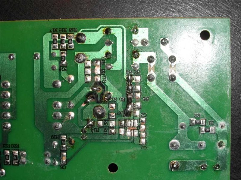
On the forums, it was advised to remove the capacitor C5 - 100pf per 1000 volts, since it and next to it the capacitor and resistor are filled with composite for something. Over time, the composite loses its properties and begins to conduct current. These parts overlap with each other and the board burns out. I removed the capacitor and cleaned the board from the composite. Look at the photo. But these details do not affect the image and began to dig further.
In the tuner of the DRE 5000 receiver there is an electrolytic capacitor that dries out over time and begins to malfunction. And the receiver you understand is already old and out of production. It is this capacitor that needs to be removed and a new one should be soldered in its place, at 220μF 16 volts. It is easier to solder the conductor to the fifth leg of the tuner so that the tuner is not unsoldered from the board. And that was done.
I checked the DRE 5000 satellite receiver again for image quality. The squares disappeared and the signal from the dish and all channels showed clearly. On this repair of satellite receiver The DRE 5000 was finished and the receiver was handed over to the customer.
Finally, have a laugh, watch the video ...

