In detail: do-it-yourself repair of the Supra TV is not included from a real master for the site my.housecope.com.
SUPRA STV-2084E3... When you turn on the TV without a signal, such a picture is observed. The lower part of the frame is present, the upper part is absent, the separation is not clearly expressed, there is no pronounced separation strip. When a signal is applied, a normal image appears, but just above the middle of the screen, there is a black arrow-shaped stripe at the end. It turned out that the malfunction was in the frame scan output circuit, the capacitors and electrolytes of the output and feedback must be replaced.
SUPRA STV-1484 The image on the screen is sluggish (graphics are displayed normally) after two to three hours, according to the owner, it is restored. There was not enough strength to check this statement, after a day of work nothing has changed. The fault consisted in the breakdown of the LZP. After replacing it with a piece of wire, the normal operation of the TV was restored. The quality of the picture was quite satisfactory for the client.
Supra STV-2084DK When turned on, a squeak is heard coming from the power supply, the TV does not start. When checking the secondary circuits of the power supply unit, it turned out that + 12V and + 18V are normal, and instead of + 115V, only +28 - 30V. When the power was turned off from the horizontal scan, the voltage increased to + 115v. Checking the SPLIT of the transformer and its secondary circuits yielded nothing. When the scribe was connected, the voltage again sank to + 30V. I measured the pulsations on the D8075 diode with an oscilloscope and it turned out that the constant level is somewhere around + 30V, and the variable pulsations are higher. I replaced the diode, but it did not help, then I replaced the C8075 33.0x160v and everything returned to normal, the TV started up.
| Video (click to play). |
SUPRA STV1484DK chassis PC04 Very dark, almost invisible image, OSD behind the threshold of the tube closing. On cathodes of 220 V. Supply voltage VVU 240 V. instead of 180 c. It turned out: in the power supply circuit of pin 3 of the split tr-ra up to L804P 118 v. and cleanly, and after, at pin 3, the horizontal frequency pulses. Reason: C807S capacitance loss 47UF 160V.
SUPRA STV1484DK chassis RS04 When turned on with the network button, the TV enters standby mode and does not respond to commands from the remote control and from the front panel. It turned out that the STENDBY 12V voltage is not filtered. Reason: loss of capacitance C804S 1000 uF 16 V. After replacement, it turns on normally.
DAEWOO DMQ-1427/1457/2027/2057/2127/2157; SUPRA STV-2024; SHIVAKI STV-2012M4; NAM DMQ-2046 (Chassis: C-50); DAEWOO DTK-2053 (Chassis: C-52).
1. Tuning frequency drift. The inverter is built on the TA8701N. More often the L124 circuit is faulty (connected to pin 22), similar to the AFC circuit in AKAI CT-1407/2007 / 2107D. The built-in capacitor 47-51 pF is subject to replacement. The failure of the L125 circuit is also possible, its parameters are similar to those of L124. After replacing the capacitors, the usual procedure for sequential adjustment of the loops to the normal operation of the auto-lock system of stations.
2. Distorted, weak sound. The L128 circuit connected to the pin is guilty. 9 TA8701N. According to my data, the built-in capacitor has a nominal value of about 15 pF. We change it and tune it to the optimal sound.
SAMSUNG CK-3351/3362/5051/5314/5342/5361, SUPRA STV-2094 (Chassis: P68SA / SC), SAMSUNG CK / CW-3335/5035/5041/5081/5082/5318/5341 (Chassis: P69SA) , (Not less favorite devices of telemasters :-).
Does not keep the frequency of tuning to the TV program. These devices are built on the TDA8362 multifunctional microcircuit, which has only one tuning circuit at the IF frequency, connected to legs 2, 3 of AFC DET (T104). Again, the built-in capacitor with a capacity of about 68 pF is to blame. We change it to a hinged one and sequentially adjust the contour to normal auto-capture of stations (the setting is quite sharp).
Supra STV-20 on STR50103A - does not turn on from standby mode without warming up for 30 minutes. Change С4.7 * 50v to (+ 16v), set no more than 10.0
Supra CTV1485 MC-41A chassis, aka Goldstar GF-14/20 / 21A80 MC-41A / B. In SEKAME there is no blue color, in PAL everything is OK. In SECAMA, the blue B-Y core circuit is L504, does not react to rotation.Do not rush to change the TA8750AN microcircuit, swap the L504 and L502 circuits connected through capacitors to pins 35 and 29 of the TA8750AN. In my case, after rearranging the contours in places, everything worked, obviously, the soldering of the legs (inside) of the contour affected, after which a small adjustment of the contours is required.
SUPRA STV-2084... There is a high and a sound, the picture tube is locked. After about half an hour, a picture appears. Dried C416 50.0X250V.
SUPRA STV2128... Changing the size of the raster when changing the contrast. Dried condenser 1.0x160 V in the power supply unit.
Supra STV-2017... When turned on, a characteristic squeak is heard from the power supply. After five minutes of warming up, the squeak stops. During the squeak, some programs go astray. I soldered the PSU and SR and changed the capacitors in the PSU - everything is OK.
Supra STV 2112W aka Shivaki STV-2017M4. A noteworthy defect. Came to be repaired with a broken HOT. After the replacement, by the evening when it was taken out of standby mode, the transistor was knocked out on a new one. During further repairs, an interesting feature was noticed. When switching the device to the duty room, the line does not turn off. When turned on, like in American cinema, the TV started working instantly. In standby mode for ms TDA2579V, (master) in standby mode, the supply voltage is absent. Short-circuited the ms output on the page r.-ku to ground, the lower case still works. I planted the base of the pre-exit tr-ra on the ground, one devil is working in full mode. The defect turned out to be in the 115 volt supply. Made in the same way as in the old GoldStar, two tanks, one after the diode, the second after the choke. The second was dry. The power supply of the TMS is also taken from 115, and the pickup from the horizontal scan was enough to support the generation on the TMS.
Supra STV-2128MS and other TVs assembled on the C-50N (C-50AN) chassis, STR50103A is used as the main element of the power supply. The raster is narrowed both vertically and horizontally, at the top of the screen there is a twist in the frame, the adjustment to the channels is lost. When measuring the output voltage of the power supply, we observe a voltage of 60% of the nominal. When replacing electrolytic capacitors in the power supply unit C832, C830 (1μF / 160V), the malfunction disappears.
DAEWOO, SUPRA, ELEKTA (Chassis C-50NA) Defects manifest themselves in different ways: no start-up, narrowed screen horizontally and large vertical size, vertical twist. And there is only one malfunction - a low supply voltage of the power supply unit. Change C830, C832.
Supra STV-2900XT... No startup lowercase / no high. When measured on IC803 (7812), the input is 6 volts. It turned out that channel 12v is connected to channel 27v, and with a punctured personnel microcircuit, we have such a failure. Replace TDA3654Q.
Supra, STV-2024... No color, buzzing on sound. Unable to configure UPCHI. The inverter runs normally from the generator. Defective transistor Q503 (2SC3198) in the SYSTEM switching circuit.
Supra STV-2900XT... Fault: after replacing a burned-out 1000 pF 2000 V capacitor in the horizontal output stage, the horizontal scan does not start. When measured on IC 803 (7812), the input is 6 volts. The stabilizer output is overload. It turned out to be broken by the power supply of the TDA8145.
SUPRA STV2024 Fault: the standby mode does not light up, the TV does not turn on, no 103v., Breakdown of C453 3.3x250V on the picture tube board.
Supra STV2128... Chassis C-50N. Fault: very quiet sound. Normal operation was restored when the TA8701N IC was replaced.
SUPRA STV-2062DK (chassis C500) The main power supply is assembled on STK73410II. Fault: does not turn on from standby mode. Replace it and two litics C808 and C810.
SUPRA STV2084DK... (The scheme is typical for GOLDSTAR TVs). Fault: the screen is dark, when an accelerating voltage is added, the image appears with a strip at the top of the screen, when the + V supply voltage is added, the strip disappears, the image becomes brighter. The supply voltage of the video amplifiers has been increased to 224V instead of 180V. The C8065 47.0x160v turned out to be faulty. Along the way, I replaced the capacitor C406 1.0x160v.
Supra STV-2017. Fault: the raster is narrowed horizontally and vertically, a fold in the image is frame-by-frame, the power supply is squealing. The voltage under load drops to 70V. Defective C830 (1.0x160V)

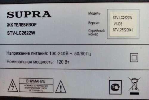
Recently, an active reader of my blog Master Sergey sent a story about his successful LCD TV repair Supra STV-LC2622W... His TV stopped turning on and he turned to me for advice.We read below what came of this.
LCD TV model SUPRA STV-LC2622W version V1J03
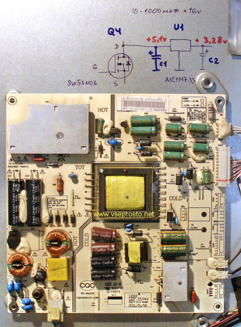
Inverter + PSU- MIP260B
Mine board-B.LT918C:
Processor - I could not disassemble it, because it is located under the radiator,
flash - 25L4005A MC
RAM - H5DU1262GTR-E3C
video processor - TDA8890H1 / N1B
tuner - TDQ-6F61T1260W
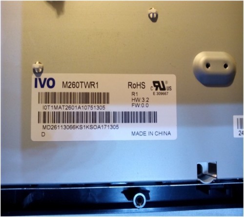
Matrix: M260TWR1.
Sergey began repairing the Supra LCD TV - he disassembled and checked all the tracks - it seems to be intact, then he checked the ceramic capacitors. I rang the details for a short circuit, I did not like the PWM microcircuit, because it had two legs closed.
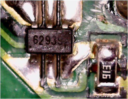
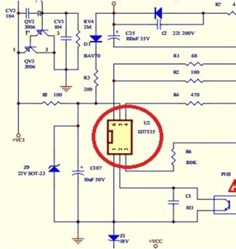
This chip OB2262, analogues - OB2263, SG6848, SG5701, SG5848, LD7535, LD7550. Sergey replaced the PWM - put the LD7535, as shown in one of the diagrams for a similar TV.
When the TV was turned on, the duty LED blinked and clicks were heard in the speakers. From the remote control it turned on like this: when the voltage appeared, the standby mode came on and by pressing the remote control several times it was possible to get into the turn-on time and turn on the TV.
I measured the rest of the voltages - they appear and disappear in time with the blinking of the duty room LED.
I advised Sergey to replace the small electrolytes with which the PWM microcircuit is hung, because in my practice I periodically meet such defects. But it seems that the solution to the problem was different.
Sergey bought for 100 rubles. another microcircuit OB2263 and everything worked - the voltage is normal.
Turned on the TV - it works well, the remote control listens, but sometimes it does not turn on from the button on the TV. The details I checked on both boards do not heat up. Perhaps the power button needs to be cleaned. The repair was completed successfully and Sergey wrote the following a comment:
“… Denis, thank you so much! ... and can I describe to you such a case with my TV, I was not the only one who suffered so much ... I found it on the Internet with the same power supplies. If you write on your website, you will help radio amateurs. " Therefore, as I promised, I am spreading Sergey's case about the successful repair of the Supra STV-LC2622W LCD TV with my own hands - someone will definitely come in handy.
Then we switched to communication by e-mail and Sergey told how he repaired the soap bubble generator. But that's a completely different story.
I am writing for all readers of my blog - bolder ask for support to knowledgeable people on the Internet. Just describe your problem in detail so that the desire to help you does not turn into an interrogation. I am for freedom of information on the Internet and its benefits for ordinary people.
After working in the kitchen for about three years, suddenly such a small Supra LCD TV went out and stopped turning on. He did not react to pressing the buttons on the remote control and on the TV itself. The LED on the TV, somehow not stable, sometimes switched from red to green and vice versa.
I made a small animation. This is approximately how it looked in real life.
To begin with, I decided to delve into it myself, since sometimes I managed to fix the TVs on my own, although those TVs were tubular. He took it off the wall, disconnected the external power supply and antenna. After that, he unscrewed the homemade bracket so as not to interfere with the disassembly of the case.
This is actually its marking, model, number and other dregs.
I unscrewed ten self-tapping screws around the entire perimeter, they are not all the same, so we remember which one from where.
Then remove the cover. If you look at the photo below, then it must be pulled out from under these connectors, since it is slightly pressed by them.
Something like this looks like the insides of this TV model. Its power supply is external, and there are only a couple of boards inside the TV. Since I am far from an electrician, even very far away. Then he decided to inspect it himself, and then call specialists. For half a day I bumped it, in the hope that the breakdown lies in a bad or loose connection. I checked the voltage on the power supply with a tester, even changed it to another one, with a current slightly less than the prescribed one. I disconnected all the cables from the main board in turn. I also tried to find something suspiciously heating up, burned-out tracks on the board, etc. etc.
As a result, this TV was sent to x. (to the master), or rather, I summoned the master to him. Fortunately, their sharashka is located not far from the house, or rather the master is not far, since they most likely work in the districts, and the workshop itself is devil-where. He came quickly, for where else they give almost a piece for a look. With the tester, he poked a couple of times into the small board on the left (pictured below). I checked the power supply, then jabbed my finger at the processor (I think so) on the main board and said that it should be changed. Then, according to the price list, he named the approximate price of this upgrade, something about 3000r (the cost of the same TV at that time was about 5000r). Then he wrote out a referral to the workshop so that they would not do the diagnosis a second time.
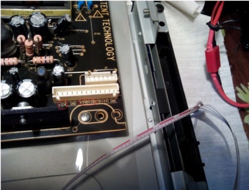
In order not to further sponsor a home appliance repair company, at a family council they decided to buy a new TV for the kitchen. Yes, they have already picked it up and ordered it in an internet store. But since the order came on the weekend, there were still three days to wait for it. During this time, I tried to find friends in the network in misfortune. And on some forum I found something similar, where a person raised the topic of a malfunction with about the same symptoms as mine. There, in the comments, people referred to a voltage regulator, at the output of which the voltage sags. As a result, the TV does not turn on and does not react to anything.
It is located near the white shoe on top, under the black tourniquet. Having measured the voltage between the first and second terminals, it turned out that it is almost twice as low as 0.6v. Although there on the forum they say that there should be 1.26v.
Somehow this monster looks like this (stabilizer BM1117-ADJ), in size it is slightly larger than a match head 🙂 After going through a bunch of pieces of iron in the apartment, I found something similar, but with slightly different markings. Therefore, I decided to go to the Tsaritsyn radio market to find exactly the same one. But we couldn't find the same stabilizer there. Those who sell purely parts didn't have it. Unfortunately, I didn’t get it on used boards.
On bezrybe, I decided to put the one that I found on my sound card from the computer, that is, AMS1117.
For clarity, I sketched a diagram of the work done (photo below). After installing AMS1117, the voltage on pins 1 - 2 became 2.2v. But the TV still didn't turn on. Using the poke method, I tried to lower the voltage by soldering the resistor into the gap of the third terminal. I got this resistance by about 3-4 Ohms. Then the TV started up fine.
Attention!
I am not an electrician and not even a radio amateur, I did all this out of sports interest, with the expectation that if I did not fix it, I would throw it out the window 🙂 Therefore, if you are afraid to set yourself or the TV set on fire, then in no case do all this. Either look for the original stabilizer, or bring it in for repair.
Since I have no resistance for 3-4 Ohms, I had to make it up of four resistors of 10 Ohms each, connected in parallel. In total, we got such a bandolier, which was melted into the rib of the TV case. And I stretched the ends from it to the stabilizer and the board. Due to the tightness, I had to solder the stabilizer itself with its end to the board. In general, in the pictures below, you can see this whole vegetable garden 🙂
In general, I had to cancel the order for a new TV, since this one has been working for a week. If you have the same TV or the same signs of illness, then try to find this stabilizer on the board and measure the voltage at its terminals. Perhaps your TV has something similar and you just need to replace this part. Most of all, it was upset that the master immediately rejected the TV. He didn't even bother to ring the processor's power supply circuits, or at least he would pretend that he was looking for a malfunction. Almost immediately straight to the forehead, take it to the workshop and give it another 3000. In my opinion, all his diagnostics initially boiled down to checking the power supply. The devil only knows how correct all this is, but so far everything works great.Maybe over time, experts in their field will unsubscribe in the comments.
After working with the new stabilizer for about a month, this TV still did not turn on about three times during this period. Therefore, out of four resistors, I had to leave only three, biting off one of them with side cutters. That is, instead of a 2.5 ohm resistor, it now costs
3.3 ohm. At the moment, it has worked for more than a year, there were no more glitches with the inclusion.
Recently I found and bought on Ali in this store, here are such BM1117-ADJ stabilizers, unfortunately in China they like to sell everything in wagons, so the minimum batch of such parts consists of five pieces and costs about 200r. And since the TV for some reason still works great on my substitution from the sound card, these new stabilizers are still lying around, sealed.
Write a message to the author
Processor - MICOM - MST6E48RHS-LF-Z1-SJ
Does not turn on from standby mode to working mode. Sometimes it will turn on from the tenth time.
All voltages from the Power Supply are normal. The signal from the remote control passes. The buttons are not closed.
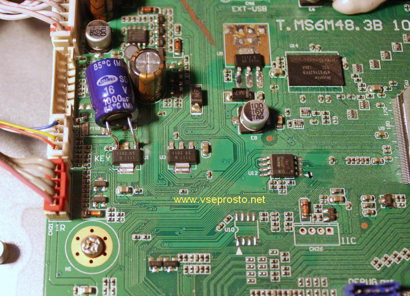
The habit, during external examination, to pay attention to electrolytes, whether they were plump, helped. I checked the power supply capacitors, visually and with an ESR meter, went to the processing board and did not find the capacitor at all. The designers did not foresee it. We could not find the datasheet for the stabilizer. In it, in Russian and white, there is a capacitor BEFORE, and a capacitor AFTER the stub.
After BS25P-1117-3.3, at least the ceramics were installed, but before it is completely empty, and this is in the impulse device, after the loop.
There is not even a place for the condenser. I had to solder the stabilizer on top.
It would not hurt to throw the capacitor after BS25P-1117-3.3, but it worked, and decided that was enough.
I drew for myself so as not to forget what I was doing, but it turned out clearly. The capacitor I added in the diagram is C1. The voltage at the drain of Q4 and at the input of the stabilizer U1 are the same. Apparently there is an impulse component in the power supply, which does not allow the TV to start normally. In such a device, a good wire will serve as an antenna for all kinds of interference, and a thin Chinese one even more so.
"Chinese" technology in recent years periodically suffers from the absence of a certain number of electrolytic capacitors, or their understatement. "Chinese" in quotation marks, because the factory Chinese equipment is assembled with high quality, but what we see in the markets of the former CIS, handicrafts not only from Chinese sheds, but also from Russian offices.
A similar defect was encountered in Samsung 29 "CRTs, when there were no capacitors in the processing board. While the capacity of the new electrolytes was sufficient, the TV turned on normally. A little dry, that's all. You can't put it into working mode.
So sometimes it is useful to look into the datasheets, and no one canceled the external inspection.
TV with DVD SUPRA STV-LC1922WD
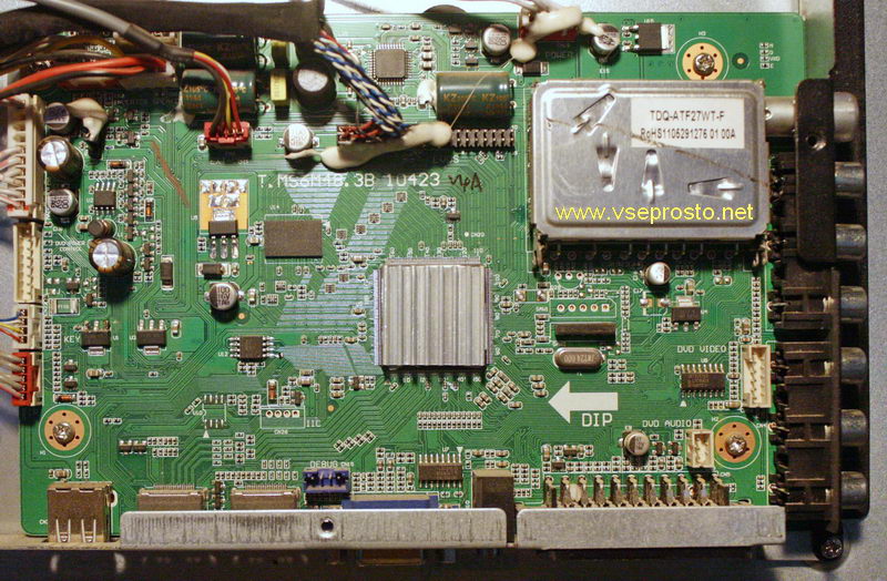
main CVMV26L-A-20
(TSUMV26KE processor
FLASH EN25F40-100GCP
EEPROM 24C02
TUNER F21WT-3BAR-E
)
matrix CLAA185WA03
Does not turn on, does not respond to buttons and the remote control.
When the power is connected, the red LED is on, with some switching on the green LED is on.
I ask for advice on where to direct your searches.
Power supply 12V (11.8V), 5V (5.2V), 3.3V (3.28) is normal.
Power supply 1.26V (U6, TP4) is understated 0.6V - what it is used for, I don't know if it's normal or not, I don't know.
The TSUMV26KE processor is receiving power. At startup, the processor carries out a short-term data exchange with the flash. There is no appeal to 24c02.
When power is applied to the TV, the voltage to the matrix, inverter, DVD are immediately turned on. The signal from the WAKEUP processor is 1.1 V and does not change when the buttons are pressed.
There is no signal to turn on the backlight when you press the buttons.
Flash unsuccessfully flashed the file
MAIN CLVM26L-A-20_LCD CLAA215FA01_25F40.bin (supra_stv-lc2222w_884.rar)
also mistakenly flashed the file
4383_STV-LC1922WD.rar from another chassis (SP208ESA).
The native firmware is broken, several pages have been erased - I probably killed it myself when trying to debug the programmer. Native firmware except for a few pages with FF is very similar to supra_stv-lc2222w_884.rar
I tried to start with another external power supply. EEPROM did not change.
I have already found the scheme.
It seems that something is preventing the processor from working normally, which is incomprehensible. Maybe try a different firmware?
Main is the same (the photo is not mine, if it is impossible according to the rules - uber)
It's a shame to throw out a TV that costs 50,000 rubles and more, on the contrary, a cheap LCD panel is sometimes easier to buy than to replace the matrix. This takes on significance in private companies, the staffing table contains a master's cell. It is not surprising that there is a keen interest in repairing TVs with your own hands, the breakdown may be insignificant, the gain is obvious. How not to be electrocuted, not to break the device? We plan to discuss with today's review, we will list the main types of faults.
The percentage of models with a cathode-ray tube is large. It is logical to start with them to consider how to repair a TV, because switching power supplies are considered an integral part of any equipment. Liquid crystals, OLED (organic diodes), plasma. Scanning chips use similar principles. The way of building the image is different, but the element base is similar. Consequently, do-it-yourself TV repair moves along the beaten path.
The equipment contains fuses. Let's open a secret: if a force majeure situation (lightning strike, power surge, equipment drop) happens, the protection should break. Almost the end catches up with the microcircuits. Start with the fuse. Of course, if the equipment is devoid of signs of life. In normal mode, the current through the fuse is zero, the repair specialists came up with the fact, put it into service. The burned-out part is removed, a 100-watt light bulb is connected to the terminals. The resistance is relatively high, it will serve as a good current limiter, the electrical circuit will slow down further to burn out.
Note. According to Ohm's law, the power released by a section of a circuit is proportional to the current. By limiting the value, we will avoid burnout of radio components. Actually, this is done by supplementing the circuit with limiting resistors. The light bulb serves the purpose of indication, makes it clear if an electric current is passing. The spiral is heating up, we see the light.
In normal mode, the light will blink, then go out after turning on the TV. Moreover, the device with such an additive works slightly incorrectly. There are two parts that often burn on CRT TVs:
- The diode bridge rectifies the current. With a sharp increase in consumption, one branch burns out. Usually two diodes fail. You can determine the suitable ones by dialing. The diode current flows in one direction, in the other the valves are locked. The circuit triangle indicates where the current is going. According to the concepts of circuitry, the current always flows from plus to minus. Accordingly, place the electrodes starting the dial tone.

- The second curious detail is a posistor operating on an inductive loop, the task of which is to remove the potential from a cathode-ray tube. Otherwise, a characteristic rainbow appears on the screen due to the violation of the movement of electrons. A thermistor or a loop may burn out. It is easy to check the circuit. You will need to turn off, then turn on the power. If the lamp that used to be on is now out, the problem is in the potential removal circuit. You can test the device, for a while it will be able to work normally without a loop.
How to understand whether the posistor is out of order or the loop is burnt out? First, measure the resistance. The posistor has four inputs. Two form a heating circuit, two - remove the potential. The resistance between the first pair will be 300 - 600 ohms, between the second - units of ohms. If you turn off the outputs going to the CRT demagnetization loop, we will exclude the section from work. The verification technique is simple. If the lamp is on with the loop, but not without, then you will have to look for a new lace. Visually - a thick wire that surrounds the cathode ray tube around the perimeter. To check the posistor with 100% accuracy, take the trouble to evaporate. After turning on the power, observe the action of the light bulb.
For reference. You cannot keep the equipment turned on for a long time with a light bulb that replaced the fuse.The device is defective, there is a large current in it. It is enough to turn on for a second to understand whether the light is on or not. Then unplug the TV plug from the outlet. It will allow you to protect the serviceable elements of the chain from the unusual load.
What else will burn? In the power supply at the input there is a large capacitor, next to it is a power transistor. Both parts are ringing. The transistor breaks through the source-drain transition, although other options are possible. If it is noticed that half of the diode bridge has burned out, it speaks eloquently: the fuse has failed. The type of breakdown of the TV indicates: there is still a malfunction inside. But it has already led to the failure of one branch of the diode bridge. Carry out the diagnostics until the lamp refuses to light up at all. The key sign of a properly working TV is a characteristic hum, which indicates that the line scan has turned on.
Forgot to give general instructions on how to repair your TV. The main board is dismantled for convenience, leaving a chance to get an electric shock even from the switched off device. It seems that no one has died yet, they got burns. You will need to discharge the cathode-ray tube electrode. Located under the rubber gasket. Without touching the metal parts with your hands, pry the rubber with a screwdriver, swinging from side to side, remove the electrode. Discharge the rod onto the body. If you see a ground loop nearby, it is better to go to it. It is clear that for a successful procedure, you need to have a European socket with correctly connected terminals on hand.
Clicks will be heard during discharge. Continue to touch the contact while the phenomenon is observed. Any modern TV set has electronics assembled by one board, which controls the operation. Many radioelements are visually assessed for their integrity. Defective capacitors swell, resistors (active elements) turn black. Darkened resistance sometimes stays good. The defect clearly indicates: the radio element closes the circuit of the broken element.
LCD TV repair is similar to the case of CRT models. The posistor is, of course, absent. It's easy to understand the cause of the backlight breakdown. LCD TVs use two types:
- discharge gas lamps;
- organic or LEDs.
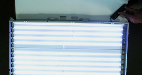
Gas lamps don't look like cousins hanging from ceilings. Rather white straws. To check the power, remove the back panel to see the wires going into the matrix. Carefully disconnect from the connector, taking a working lamp, check the functionality. It happens that a number of discharge light sources are occupied by the illumination. Take the trouble to remove the matrix, turn on the TV, see which lamp does not work, replace it.
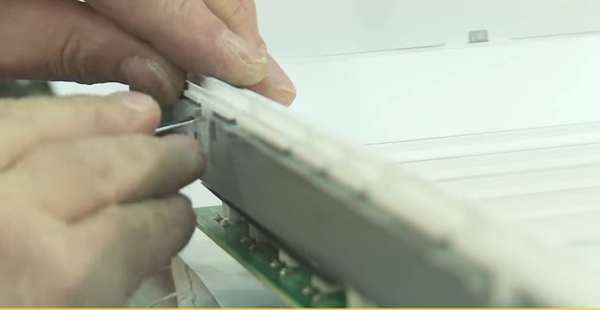
The installation scheme of the illuminators is different. In some TVs, you just need to pull out the lamp from the end without disassembling the matrix. The wires come in from both sides, each covered with a rubber gasket. The protective elements should be pushed aside, the lamp should be evaporated. Installing a new one takes place in the reverse order. Try to choose one that is equivalent in size to the replaceable one. The location of the lamp is lateral, less often the top. It happens that there are two or more illuminators. If a vertical or horizontal stripe appears on the matrix, the scanning electrode most likely burned out. Try to turn on the device with a different, known good matrix to check the assumption.
Replacing crystals on cheap TVs is not cost effective. The cost of a new spare part is more than 3000 rubles. It's another matter if you have a similar broken TV set at hand with a working liquid crystal matrix. Then the replacement is registered. Repairing a TV screen is rarely cost-effective.
There is a typical breakdown of modern TVs: they stepped on a cable. The vein is ripped out, sometimes together with the track on the microcircuit. The digital receiver is represented by a small microcircuit (which needs to be shielded), so the assembly is inseparable from the connector.Carefully dismantle the electronics before repairing. Then use glue, soldering iron to repair the part. Repair of the TV antenna will be required after a lightning strike. Users install cymbals, forget the lightning rod.
Plasma TVs are being repaired in a similar way. There is no backlight, posistors, therefore, there are fewer problems!
Probably, many are familiar with the situation when the TV stopped showing signs of life when the owner intended to turn it on. Now we are calm about this, since we understand that you can use another TV in the next room or in the kitchen, and the faulty device can be repaired over time. But, if you look back thirty, forty years ago, the refusal of the TV to turn on would be perceived as a big nuisance. TV then, despite the ideology of the programs, for many people was the only window into the world. It was in no way possible to skip the episode “Seventeen Moments of Spring”, and the feelings about this seemed quite reasonable.
There is no doubt that the technique has become more reliable and technologically advanced over time, its weight and dimensions have decreased, and many new user and multimedia functions have been added. However, nowadays, as well as at the dawn of its formation, television receivers are sometimes prone to failures when turned on. There may be many reasons for this, and the apparatus itself is not always the “culprit” of such strange behavior.
It is quite easy to verify the opposite. You need to check the electrical outlet where the cable from the TV is inserted. Plug in a table lamp and make sure it works. Remember where your device has the power button, and if there is one at all. This is no joke, many owners forget about its existence, using only the remote control.
The assortment of TV sets is so diverse and wide that even a master on TV in a model not very well known will take some time to find the mains switch. These elements of the scheme tend to hide in nooks and crannies, below, on the side, behind and be completely invisible. Accidentally hitting this button and not noticing it, then you can ask for a long time the question "Why does the TV not turn on?"
Of course, situations with a button or a bad outlet are not typical and are quite rare, but by checking these things it is worth starting to diagnose the reasons why the “box” does not want to turn on. Most often, the receiver itself is to blame and the owner has to make a decision whether to call a master or fix the TV with his own hands.
For many men who consider themselves technically literate, the issue of TV repair does not seem so difficult. “There you just need to replace the fuse, or something else, but to fix it you need a tester, a soldering iron and a circuit,” some confident people think so. However, the desire to repair the device on its own can decline after the cover is removed from the device and access to the boards and blocks of a modern TV is obtained.
The fuse, as we are used to seeing it, in the receiver, most often, is one and in most cases intact, if there were no farce-major circumstances in the form of a thunderstorm or large voltage surges in the electrical network. It may well be that the fuse on one of the boards has blown, but most of the "fuses" are now made in an SMD case and the search for a faulty one may take a long time, since there can be dozens of these components, and they are located in any television unit. It is rather difficult to visually determine their presence in the circuit and distinguish them from similar in appearance capacitors or resistors without proper skill.
Let's say the search was successful.Here it is - a burnt out "fuse" (fuse), which needs to be replaced and the hope that the TV will again delight us with juicy stories and heartfelt stereo sound will come true. However, joy can be premature. Questions should arise: "What is the rating of the defective fuse?" and "Why did it burn out?" If you don't think about these things and just solder a wire instead of a spare part, you can discover a lot of new things: see the smoke from a large microcircuit or hear the crackle of exploding transistors. This means that you have not found the cause of the blown fuse and, as a result, significantly increased the cost of further repairs.
For an experienced TV technician, the socket for the fuse in the power supply unit hastily wrapped in wire, causes sacred awe, horror in the eyes and the understanding that this device cannot be restored quickly and painlessly, that you cannot earn a lot, and you will have to “sit” with it for a long time, looking for changing what in ordinary life is not in the habit of failing. The most unpleasant thing in this case is the unpredictability and lack of logic when searching for defective parts.
Situation analysis and assessment of the factors affecting the occurrence of a malfunction are an integral part of the professional skills that an experienced TV master... Finding the root cause due to which various components of the television chassis, including fuses, can fail, is the main task of a specialist. You cannot repair, relying on "chance", without having firm confidence that the defect will not recur in the future.
A simple example. Panasonic CRT TV does not turn on. Measurements show that a 56 volt zener diode is broken in the tuner tuning voltage generation circuit, which performs a purely protective function, and its presence or absence in a properly operating chassis is not at all necessary. Due to inexperience, when repairing with your own hands, replacing this part leads to its repeated burnout. If the zener diode is not installed at all, the TV can turn on and work for a while until the line transistor, frame microcircuit or line transformer burns out. The reason for this behavior is in the overestimated voltage that the power supply gives out, and if even deeper, in the loss of the nominal capacity of two electrolytic capacitors of 47 microfarads. in the primary circuit of this block. This is the root cause of all troubles.
There is much more to be said about why the TV won't turn on. This note focuses on the human factor in such a situation and on the fact that always when repairing a TV, as, indeed, any technically complex device, one should look for the cause and eliminate the consequences caused by it. An attempt to restore the TV's performance on its own may not always end in success. You need to be ready for such a turn and think a hundred times before deciding on this step. It may be worth calling a foreman on TV for repair and, accepting a job, pay, first of all, his experience and knowledge, and not the ability to solder and use a tester and a circuit.
Do not forget to bookmark this page on your social networks!
It is no secret that a breakdown of a television receiver can ruin the mood of any owner. The question arises, where to look for a good master, do you need to take the device to a service center? You need to spend your time on this, and what is important - money. But, before calling the master, if you have basic knowledge of electrical engineering and know how to hold a screwdriver and a soldering iron in your hands, then repairing the TV with your own hands in some cases is still possible.
Modern LCD TVs have become more compact and easier to repair. Of course, there are breakdowns that are difficult to detect without special diagnostic equipment. But most often there are malfunctions that can be detected even visually, for example, swollen capacitors... With such a breakdown, it is enough to evaporate them and replace them with new ones with the same parameters.
All TV sets are the same in their structure and consist of a power supply unit (PSU), a motherboard and an LCD backlight module (lamps are used) or LED (LEDs are used). It is not worth repairing the motherboard on your own, but the power supply unit and screen backlight lamps are quite possible.
As already mentioned, the design and principle of operation of LED and LCD TVs, regardless of the manufacturer, are the same. Of course, there are some differences, but they do not play a significant role in the diagnosis of faults. Often, in the event of a problem with the power supply, the LCD TV does not turn on at all, while there is no indication, or it turns on for a while and turns off spontaneously. Using an example, the repair of a DAEWOO LCD power supply unit (can be applied to plasma) is considered, which is not much different from repairing an LG TV, as well as Toshiba, Sonya, Rubin, Horizon and similar models.
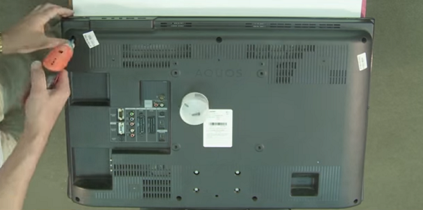
- First of all, before you repair the TV, you need to remove the back panel of the device with a screwdriver by unscrewing the screws. On some models, the rear wall may be latches installedwhich must be handled with care so as not to break them.
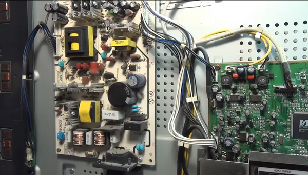
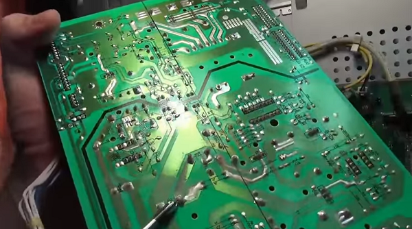
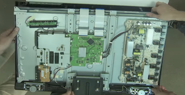
- After removing the cover, you will see the power supply unit, consisting of several modules on the left, and the motherboard on the right.
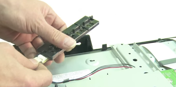
- On the power supply board you can see 3 transformers: the bottom one is the mains rectifier choke, the top one on the left (large) feeds the inverter, and on the right is the standby power supply transformer. You need to start checking with it, since it turns on the standby mode of the TV receiver.
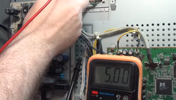
- Duty transformer when the device is connected to the network, it should give out a voltage of 5 V. In order to correctly find the wire on which you need to measure the voltage, you can use the diagram, or you can see the markings on the case. In this case, opposite the required contact is written - 5 V.
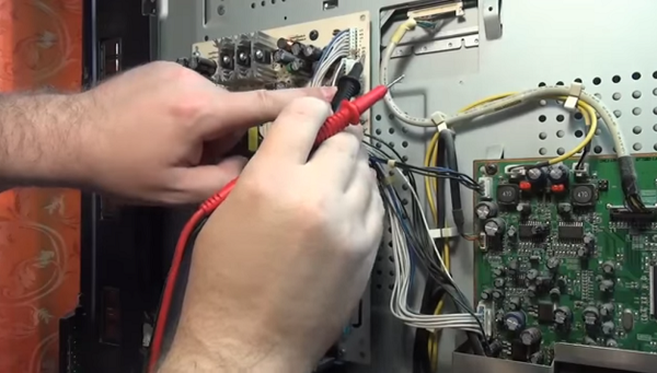
Measurement is taken first open circuitby connecting one probe to the found contact, and the other to the cathode of the diode on the radiator. In this case, there is no break. 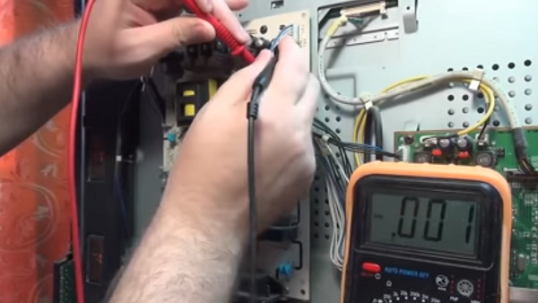
As you can see from the review presented above, repairing TV power supplies with your own hands is not such an overwhelming task. Following this description, you can also repair plasma TVs.
Do-it-yourself TV repair with a kinescope, for example, such as: Rubin, Horizon, Sharp 2002sc, LG TVs, as well as repair of the Vityaz TV, begins with checking the power supply unit for operability (this is done if the unit does not turn on).It is checked using incandescent bulbs for 220 V and a power of 60-100 W. But before that, be sure to disconnect the load, namely the horizontal output stage (SR) - connect a lamp instead. The CP voltage ranges from 110 to 150 V, depending on the size of the tube. Must be found in the secondary circuit SR filter capacitor (its values can be from 47 to 220 microfarads and 160 - 200 V), which stands behind the SR power rectifier.
To simulate the load, you need to connect a lamp in parallel to it. To remove the load, for example, in the popular Sharp 2002sc model, it is necessary to find and unsolder the inductor (located after the capacitor), the fuse and the limiting resistance through which the CP stage receives power.
Now you need to connect the power supply to the power supply unit, and measure the voltage under load. The voltage should be between 110 and 130 V if the CRT has a diagonal of 21 to 25 inches (as in the 2002sc model). With a diagonal of 25-29 inches - 130-150 V, respectively. If the values are too high, then it will be necessary to check the feedback circuit and the power supply circuit (primary).
It should be noted that electrolytes dry out during prolonged operation and lose capacity, which, in turn, affects the stability of the module and contributes to an increase in voltage.
When the voltage is too low it is necessary to test the secondary circuits to exclude leaks and short circuits. After that, the diodes for the protection of the power supply of the SR and the diodes for the power supply of the vertical scan are checked. If you are convinced that the power supply unit is working properly, then you need to disconnect the lamp and solder all the parts back. This check can also come in handy when doing DIY Philips TV repairs.
Another common breakdown of the TV that can be eliminated is the burnout of the backlight lamp. In this case, the TV receiver, after switching on, flashes the indicator several times and does not turn on... This means that after self-diagnosis, the device notices a malfunction, after which the protection is triggered. That is why there is no image on the screen.
For example, a Sharp LSD TV receiver with this malfunction was taken, although in this way it is possible to repair Samsung TVs, Sony Trinitron, Rubin, Horizon, etc.
-
To fix the TV, you need to remove the back cover from the TV. This requires a screwdriver or screwdriver.
Next, you need to be careful disconnect loops from the matrix. 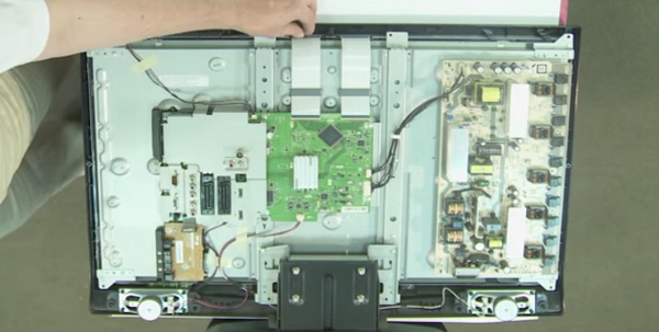
Thus, you can repair the Philips and LG TV with your own hands, and other LCD panels, as well as devices with LED backlight (LED). Owners of the latter type of devices should read the article on repairing LED backlighting, where the whole process is described in detail using the example of an LG TV.
Among the typical and simple reasons that the TV set does not turn on, there may be a remote control or a lack of signal from the antenna cable.
If the TV does not turn on with the remote control, first, you need to make sure the batteries are good. If they are shrunken, replace them. Often the TV set cannot turn on due to contamination of contacts under the buttons. To do this, you can disassemble it yourself, and clean the contacts with a soft cloth from accumulated dirt. If your remote control has been dropped, it is possible damage to the quartz emitter... In this case, it must be replaced. Well, if you filled the remote control with water or some other liquid, and it did not work after disassembling and drying, then it will have to be replaced with a new one.
You can learn more about fixing the remote control in the following video or article.
When repairing TVs LG, Sharp with LCD, Rubin, Horizon with the same screens, a situation often arises when it does not turn on when the device is in good working order. It turns out that the reason may be no TV signal in the antenna cable. This happens due to the operation of the noise suppression protection (in Rubin TVs, they began to install it not so long ago), and the unit goes into standby mode. Therefore, if you find your TV set inoperative, you should not panic, but you need to check the presence of a signal from the transmitting station.
In conclusion, we can say that when you decide to repair a TV set yourself, you should soberly assess your abilities and knowledge in this matter. If you do not feel confident, then it is better to entrust this matter to a telemaster, especially since nobody canceled 220 V, and ignorance of basic safety rules can entail unpleasant consequences.
| Video (click to play). |


