In detail: do-it-yourself fan repair from a real master for the site my.housecope.com.
Dear site visitors.
I believe that the information provided in this topic will be useful to you. The topic will touch upon various issues in this area, and there are many questions about this part:
- how the electric motor of a household fan works;
- how to replace a capacitor in a fan electrical circuit;
how to rewind the fan motor stator, how to repair:
- wall fan;
- ceiling fan;
- window fan;
- floor fan;
- bathroom fan;
- fan for the kitchen;
- fan with timer;
- exhaust fan.
It is almost impossible to state immediately and completely information on emerging issues related to a malfunction as a result of the operation of various types of electric fans.
The topic will gradually expand, that is, after a certain period of time, additions will be made.
Be interested in various sources of information in this direction:
- technical sites;
- technical literature
etc. Accumulate your experience and knowledge.
desktop fan Vitek
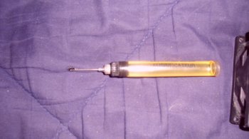
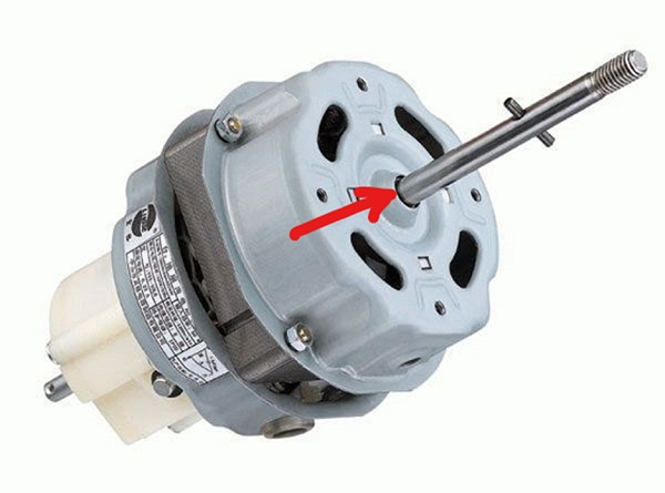
Let us consider in detail how the fan motor is checked. As an example, an electric motor is shown that corresponds to a variant of household table fans.
The photo shows the small electric motor of photo # 1 of the desktop fan. To present this topic more clearly, the explanation will be accompanied by personal photographs - by diagnostics of the electric motor.

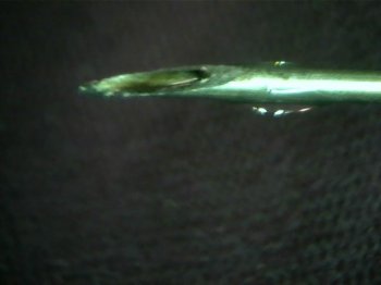
Diagnostics of electrical connections begins with a preliminary check of the device itself, photo No. 2.
| Video (click to play). |
Why is such a check necessary? - The test is carried out to ensure that there is no break in the probe leads of the instrument. That is, in practice, such a device malfunction as a wire breakage in connection with the probe is often encountered, a metal pin in connection with a wire.
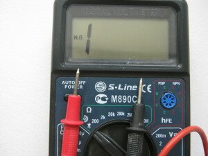
In the event of a break, for a certain section of the electrical circuit, the display of the Multimeter shows a "unit". If two probes of the device are short-circuited with each other when the range of least resistance is set, the display of the device will show a zero resistance value. For this example, this will mean that the device is working properly.
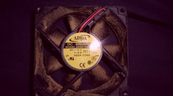
Let's start by checking the capacitor, which is in the electric circuit of the electric motor, photo # 3.
Here we can clearly see that the capacitance on the capacitor case is:
- 0.51 microfarads;
- deviation - + -10%;
- permissible rated voltage - 630 Volts.
To check the capacitor for the presence of photo # 4 capacity, you need to disconnect it from the electrical circuit and cut off the wires with scissors. Before measuring its capacitance, it is necessary to discharge the capacitor, short-circuit the contacts of the capacitor and then carry out the measurement.
For a given capacitor capacity, the device is set in the range from 200 nanofarads to 2 microfarads, since the capacitance of the capacitor is 0.51 microfarads and the set range corresponds to our measurement.
The display of the device photo No. 6, as can be seen from the photograph, when measured, shows at the same time - 0.527 microfarads. This capacitance indicator is quite consistent with the capacitance indicated on the capacitor case, since the deviation in the capacitance is taken into account here.
So, when checking the capacitor of the electric motor in the circuit, we made sure that the capacitor is serviceable, the capacitor plates are not broken, and we should proceed to the following checks.
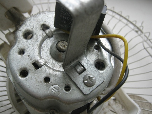
Four wires of photo # 7 are removed from the stator windings of the electric motor, and for this check we need to measure the resistance of each of the two windings.
The first thing we need to do is set the device to the appropriate resistance measurement range.
Next, we connect the probes of the device with one pair of wires of the same color as shown in photo # 8. The display of the device during this measurement shows a value of - 1125, more precisely, such a reading will be - 1, 125 kOhm.
When measuring the second stator winding of the electric motor photo No. 9, the display of the device for this example, shows the number - 803. That is, more precisely, the resistance of the second stator winding of the electric motor is - 803 Ohm.
To measure the total resistance of photo # 10 of two stator windings, one pair of wires must be short-circuited and two probes of the device must be connected to the second pair of wires. This method is final and more accurate to identify the integrity or rupture of the series-connected two windings.
The display of the device, as we turned our attention, shows the total resistance of the two stator windings of the electric motor - 1927, or rather 1.927 kOhm.
In case of any short circuit in the electric motor circuit, the device will indicate a zero resistance value, as shown in photo 11.
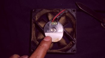
So what is the table fan motor in Figure 12? The fan motor is asynchronous, single-phase with a squirrel-cage rotor.
Why squirrel cage rotor? - You ask. Because the rotor, as can be seen from the photograph, is made by filling the core grooves with molten aluminum, as well as casting on its short-circuiting rings - fan blades. More precisely, it is not visually observed here - the rotor windings.
The blades on the rotor serve both for cooling and for air circulation of the electric motor. The capacitor serves for the initial shift of the rotor starting the rotor.
The rotor speed in the rotating electromagnetic field of the stator of this type of motor is 1200 rpm. The input power of such a motor is low - 60 W. The power consumption is generally comparable to the power of an incandescent light bulb.
The electric motor in its design is simple. The single root cause of a motor malfunction here could be:
- burnout of the stator windings;
- capacitor malfunction.
We figured out the electric motor, disassembled it thoroughly and now, of course, we need to learn how to correctly make the wire connections. That is, it is necessary to correctly connect the electric motor, if the connection is incorrect, the electric motor will simply fail.
According to the diagram in Figure 1, it can be seen that the electric motor of the desktop fan consists of two windings:
If you look at the photographs, you will notice that the stator consists of four coils. That is, each winding in this example consists of two half-windings, so to speak.
When measuring the resistance of the first winding, the resistance was 1.125 kOhm. When measuring the resistance of the second winding, the resistance was 803 ohms.
We need to correctly connect the capacitor in the electrical circuit of the electric motor.
So friends, for a reminder, we are considering connecting a single-phase asynchronous squirrel-cage motor.
For the correct connection of the capacitor, which is in the electrical circuit of the motor, it is necessary to determine:
stator winding. The capacitor in the circuit is connected in series with the starting winding.
Here you need to learn that the starting winding has the highest resistance in terms of its value, and in this version, this resistance is - 1.125 kOhm. In no case should the capacitor be connected to the working winding - this will lead to burnout of the stator windings of the electric motor as a result of the initial occurrence of a large starting current.From the section of electrical engineering, we know that the strength of the current increases - as the resistance decreases.
floor fan elenberg
We are meeting again on this page, and I consider it my civic duty to share my experience and knowledge with you.
Recently I was given an Elenberg floor fan for repair. The renovation was accompanied by the execution of personal photographs and this will serve you in the future as a small workshop. The reason for the malfunction of the floor fan at the beginning was not clear, of course it was necessary to disassemble the fan in order to check individual sections of the electrical connections.
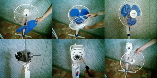
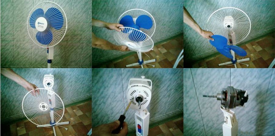
To make it more convenient to repair photo # 1, let's disconnect the fan itself from its rack. Next, we need to remove the protective metal frame of the fan for the convenience of repairing photo # 2, photo # 3.
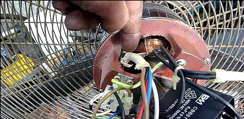
Then, we need to free the plastic cover from the electric motor in order to completely inspect and directly check the fan motor itself. That is, it is necessary to unscrew the bolted connections of photo # 4, photo # 5.
After removing the plastic cover of the electric motor, we will be able to check specifically both the electric motor itself and the capacitor in the electrical circuit of photo No. 6.
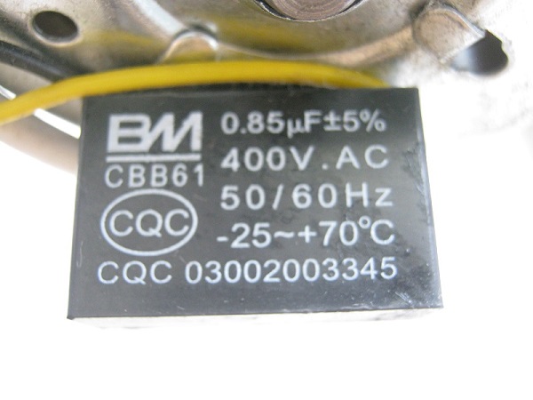
Capacitor photo No. 7, which is in the electric circuit of the electric motor of the Elenberg floor fan, contains the following values:
- capacitor capacity - 0.85 microfarads;
- rated permissible alternating voltage of the capacitor - 400 Volts
Other values indicated on the condenser are not so important in carrying out repairs. We need to check the capacitor, set the multimeter in the range of the measured capacitance of photo # 8. The capacitance of the capacitor for our example is 0.85 microfarads, that is, the device is set in the range from 200 nanofarads to 2 microfarads.
The capacity is quite consistent with the value indicated on the capacitor case, photo # 9. As can be seen on the display of the device, the measuring capacitance is 0.84 microfarads. Given the tolerance: + -5%, the capacitance is not completely lost and the capacitor is valid.
What else do we need to check? - Of course, the fan motor is photo # 10.
And what are we seeing here? - The multimeter display shows the total resistance value for the two stator windings of the electric motor - 1215 Ohm or more precisely - 1.2 kOhm. It follows that the fan motor and the capacitor are in good working order.
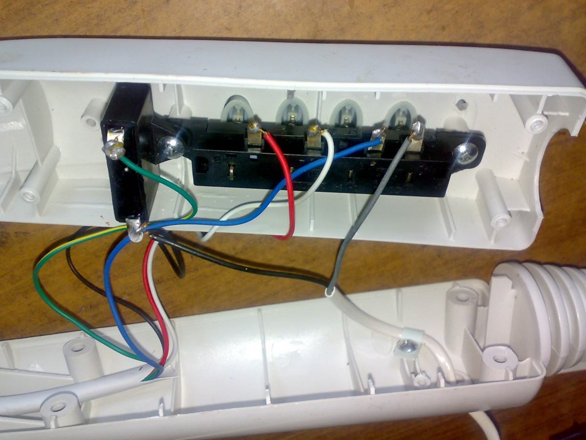
So what is the cause of the floor fan malfunction? What else do we need to check? We need to check directly the power cord itself, as well as the switch, which is in series connection, photo # 11.
We unscrew the bolted connections to inspect the fan switch and also we will need to check the cord in the connection from the electrical plug to the connection with the switch photo # 12.
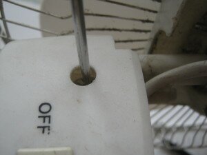
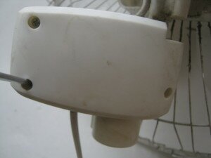
In photo # 13, you can see that the black-insulated wire is sealed from the contact with the switch. That is, the switch for this example is not connected to the fan circuitry.
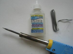
We eliminate the malfunction by soldering tin photo No. 14, for repair we need:
- soldering tin;
- soldering acid or other solder;
- soldering iron.
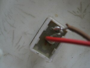
On the place where the wires are connected after soldering with tin, cambric is put on for insulation. This image of photo No. 15 shows the connection of the capacitor, this method of isolation is simple and convenient in carrying out any kind of repair of household appliances.
So we fixed the Elenberg floor fan. The malfunction was in the simplest reason, a break in the electrical connection - through the fan switch.
So friends, we went through a little training - how to use a digital multimeter.
The topic will be supplemented with information on various types of fans.
Soldering the switch is not difficult, but using acid solder for soldering wires is not entirely correct.Flushing the soldering point may not be able to wash off all the acid from the wiring. And the acid residues will slowly erode the wires and the wires will again fall off the switch. In such cases, you need to use an acid-free flux - for example, rosin, or something similar. Good luck with this work.
Hello. I agree with you, rewinding an electric motor is a laborious job.
If a household fan breaks down, both desktop and floor-standing, do not rush to immediately take it for repairs, let alone throw it away. Most likely, there is a simple problem, and you can repair the fan yourself.
The household fan does not differ in design complexity, and the principle of its device can be seen in the figure below.
If you look closely at the drawing, it becomes clear that an electric motor, a gearbox, a crank, a rotation speed switch and a propeller that creates an air flow can fail in the apparatus.
The main difference between a desktop cooler and a floor-standing cooler is a high stand in the floor-standing version. The rest of the designs are identical.
So, the main malfunctions that you can observe with the cooler you purchased:
- the unit does not turn on, the power lamp is off;
- the device does not work, but the light is on;
- cooler blades do not rotate well;
- the unit does not turn to the sides;
- cooler hums and does not rotate.
In this situation, there can be 2 options: the lamp indicating the readiness of the unit for operation can light up or not. Depending on this, the breakdown diagnostic algorithm will differ.
If, after turning on the device, the light located on its body does not light up and it does not start, then, first of all, you need to check if there is outlet voltage... This is done simply: take any electrical appliance and plug it into this outlet. If the device works, then you need to look for a malfunction in the electrical plug and cord.
To check the plug, unscrew it and check the reliability of the wire connection to the terminals. To check the cable, you need to disconnect it from the terminal block of the device and "ring" the tester. If a break is found in the cable veins, it should be replaced.
The reason for this behavior of the unit, when the indicator light is on, but the fan does not work, and no sounds are heard, may be caused by breakdown of the block with buttons... To test the buttons, you need to disassemble the button block located on the floor fan stand or stand near the tabletop apparatus. But, before disassembling the device, make sure that it is unplugged from the outlet.
The operation of the buttons is very simple: there is an “on” and “off” position. It is necessary with a tester to check the “output” and “input” on each key.
If a faulty button is found, it cannot be repaired. Therefore, the switch must be replaced or a direct connection made. This approach to solving the problem will help to start the unit into operation if you are far from the store, for example, in the country.
Defective speed switches can also be the reason why the fan does not turn on. To test the regulator, you need to put it in the maximum position and check the “input” and “output” using the same tester.
In the case when the fan does not pull and does not drive air well, it will be necessary to disassemble the case in which the motor is located. Sometimes the fact that the propeller is not spinning can signal that there is insufficient lubrication in the plain bearing installed in the electric motor.
The fan is disassembled as follows.
- First you need to unscrew the protective mesh (its front part) and remove it.
- After the net, detach the propeller. It can be screwed onto the motor shaft with a left-hand thread nut. That is, to unscrew the nut, rotate it clockwise, and to tighten it - counterclockwise.
- Remove the rear protective mesh by unscrewing another nut.

How to fix a floor fan if it has stopped spinning (turning) on the sides? It's all about crankthe fastening screws of which may loosen or come loose. To find out, you will need to disassemble the motor housing. If, during the operation of the unit, the body turns with a delay or a complete stop, then you should check gears in reducer for engagement. You also need to check the gear switch itself, namely, moving it up and down.
Disassemble the gearbox and remove the main gear. The shaft will also have to be pulled out. Apply grease to all moving parts and assemble the gearbox. If the gears are badly worn out, they need to be replaced, although it is quite difficult to find analogs for broken parts for the fan. In this case, you will have to assemble the unit without a gearbox and use the cooler as usual, when the air masses will move in one direction.
Cases when the fan does not spin and the motor hums are quite common. There may be several reasons for this breakdown:
- lack of lubrication on the bearings (what to do, mentioned above);
- failure of the capacitor;
- malfunction of the electric motor.
Repair of the floor fan in this case comes down to checking the capacitance of the capacitor using a tester. To get to the radio component, you will need to disassemble the motor case. A detailed description of how to disassemble the case was given above. After removing the shroud, you will see a capacitor attached to the motor.
In the presented device, the capacitance of the capacitor is 0.85 microfarads. For this reason, the instrument must be set to a value in the range from 2 microfarads to 200 nanofarads, as shown in the figure below.
In this case, after connecting the capacitor to the device, you can see that its capacity is 0.841 microfarads. If we take into account the ± 5% error, then the capacity of the radio component is within the normal range, and it is not the reason that the cooler stopped working.
When repairing a fan with your own hands, in search of a breakdown it is also necessary to "ring" the electric motor. If it is faulty, the device will not turn on and will emit a hum. It is necessary to measure the resistance at two stator windings, having previously disconnected the wires going to them, as shown in the following figure.
As you can see, the resistance is also within the normal range, since its value is equal to 1215 Ohm (1.2 kOhm). Otherwise, the device will beep but will not turn on. In such a situation, you will need to rewind the engine in a special workshop.
Since the propeller of the unit, the main task of which is to create an air flow, is made of plastic (not always of high quality), the probability of deformation of the latter is high. This usually happens if the unit is left for a long time in direct sunlight or near a high temperature source. When deformed, the balance between the blades is disturbed, which causes strong vibration and noise during normal air flow.
Also, vibration of the shaft may appear due to the sleeve of the sleeve bearing that has become loose from prolonged operation.
Often, when the apparatus falls, when the blades are spinning, the protective grill is deformed... If a rotating propeller hits it, one of the blades may break.
Summing up, we can say that in different models of fans, the main units and control elements may look different. But the principles of diagnostics and troubleshooting do not change from this.
Desktop fan Mystery MSF-2428
Detailed instructions for repairing the most common faults of a household fan, the best services and the approximate cost of work
In the summer, it is difficult to do without a conventional fan. However, after taking out your old device and winter vacation, you may find that it is no longer functional. There may be various reasons for this. What to do in such a situation? Should the equipment be referred to an expensive repair? Or try to disassemble the device yourself, followed by troubleshooting? In this article, we will focus on the latter option.
Before proceeding with the actions to detect a breakdown and its elimination, it is necessary to disassemble the household appliance. You need to take this stage very seriously. The fact is that an incorrect independent approach can aggravate the situation and then the device will be completely faulty.
In order to prevent such a development of events, we strongly recommend that you follow the plan outlined below, and then the procedure will become easy and understandable.
- First, prepare the necessary tools. These are pliers, screwdrivers of different sizes, unnecessary thick fabric. You will need a container of water. Place the fan directly next to you.
- Now, using force, try to remove the protective mesh. Use additional tools as needed. Set the mesh aside. You will see three small diameter holes in front of you. These are latches.
- Pay your attention to the plastic nut in front of you. You need to unscrew it with a screwdriver. In this case, you must move counterclockwise.
- When unscrewing the nut, do not use force, because fragile plastic may simply not be able to withstand it.
- Look at the motor shaft. Be sure to remove the blades from it.
- Detach the grill from the body.
- Now unscrew absolutely all the screws that you see in front of you.
- Remove the cover that was attached to the screws.
- After removing the cover, only the gearbox and the motor itself remain on the fan.
Now that all the necessary step-by-step actions have been completed, you can be congratulated, and also, we suggest that you move on to the next most important point.
Repair of the most common malfunctions of household floor and table fans: step by step instructions
In this part of the article, we will talk about the most common breakdowns, as well as ways to eliminate them at home.
Often, fan owners are faced with the fact that the device simply does not turn on. Some attribute this to the fact that the device has not functioned for a long time, and someone sees this as a problem in the electric motor.
In order to find the problem and fix it, you need to follow these steps step by step.
- First, test the fan cord that will plug directly into an electrical outlet. To get close to it, you need to disassemble the block that is responsible for switching speeds. Remember that at the moment of disassembly the device must be disconnected from the mains.
- Then you need to check the condition of the capacitor.
- Get to all the contact wires and various connections. Call them.
- Next, you need to lubricate all bearings.
- Check the result by plugging the device into a power outlet. If it starts working, then you have fixed the problem. Machine oil is ideal for lubrication. Place a few drops of the product on the bearing at an angle to allow the liquid to flow inward.
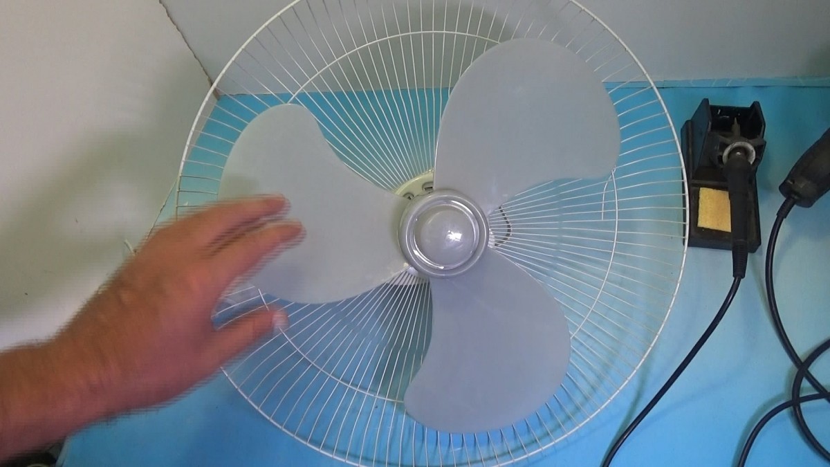
Many fans are equipped with a speed switch. However, not all shifters function as expected for long periods of time. This happens as a result of the fact that there is a breakage of the stater windings.If the winding is broken, the motor will stop functioning. In order to check the integrity of the windings, you need to abruptly start turning the blades in a clockwise direction.
Then abruptly remove your hand from the spinning fan. If after that the speed turns on abruptly, then your winding has burned out. You can buy windings at any specialized store.
They must be installed in special holes, they are fixed with screws.
Remember that the resistance of the product you purchased should not be zero or very high. Also, we recommend that you do not forget that when installing the windings, you must disconnect the fan from the electrical outlet.
Sometimes the fan suddenly starts making unpleasant sounds, hums and works loudly. This is not normal, because such a household device is usually quite quiet. It is likely that loud noise is a harbinger of future problems that are best dealt with early on.
First, you need to make sure that no foreign object has got into the device case.
It is also likely that the accumulated dust and dirt has clogged the fan sinuses, causing you to hear unpleasant noises as well. In order to make sure that you are right, or vice versa, you need to disassemble the case of the device, as it was indicated in the paragraphs above.
If necessary, thoroughly clean the blades and the indoor unit from dust. However, do not use large amounts of water.
After the performed procedures, reassemble the device and plug it into a power outlet.
The fan not only rotates the blades, but also rotates in different directions to cover the largest possible area. However, sometimes this function loses itself, and the owners are faced with the fact that the fan has stopped performing this option. The most common cause of such a breakdown is a burnt-out stator winding.
In order to check your guesses, you need to disassemble the fan. Perhaps there was a breakage or combustion somewhere. You just need to replace the winding.
In such a situation, as a rule, the device starts to work. But this is not the only reason that can serve as a failure in the function of turns.
Sometimes the reason for the termination of work is pinching the wires. Perhaps a household appliance once fell, stood unsuccessfully, or was dismantled. In such a situation, it is likely that the wires and connections inside are out of place and prevent the axle from turning. Therefore, based on the instructions, disassemble the instrument case and make sure everything is positioned correctly.
Many people forget that there is a special button on the unit body that allows the fan to rotate. Sometimes it may turn out that you forgot to press it and, thereby, blocked this function. Sometimes this button sticks, or just stops reaching the contact. In this case, you just need to push it down well, and then lift it up a little. This will design the button and it will likely function as expected again.
If you have tried several different approaches at once, but the problem persists, then you will need professional help. Finding people to help you deal with the problem is easy enough. In each city there is a point that specializes in the repair of household appliances. We will give you examples of exactly those that will masterfully cope with the problems of fans.
On average, the cost of repairing a household fan will cost you from 500 rubles to 2 thousand. It all depends on the cause of the breakdown, as well as the need to change parts. So, if the fan makes unpleasant sounds, then it just needs dust cleaning, and you will get by with very little costs.
Also, the amount you end up paying to the master depends a lot on the model of your device. The more functional and modern it is, the higher the cost.
If you want to entrust your device in the hands of only professionals, then we recommend you the Iceberg workshop network. They are located in large cities of the Russian Federation and accept any household appliances for repairs. The specialists of this network are multidisciplinary, constantly improving their knowledge. Also, a nice addition is the fast speed of service, because all the necessary tools and components are already available in the service.
Another network of workshops that have proven themselves well is the Expert Master. Located in major cities of the Russian Federation. Specializes in the repair of household appliances, as well as computers, smartphones and so on. Very good reviews, low prices. It's nice that on the official website you can find information about the pricing policy.
- Master Good. Moscow, Vernadsky prospect 24, phone 8 499 391 31 51.
- Skillful fingers. Moscow, Stroginsky Boulevard, 14, phone 849 55 65 3825.
- Iceberg. Moscow, Novospasskiy lane, 5, Tel. 8 495 723 72 30.
- Linen renovation. City of St. Petersburg, Veterans Avenue, house 9, phone 8 812 344 44 44.
- Master Service. City of St. Petersburg, Korolev Avenue 49, phone 8 812 903 52 35.
- Household appliances repair workshop. City of St. Petersburg, Moskovskoe shosse, 5 Phone 8 812 327 04 70.
A household fan is an indispensable item in the hot season. Its advantages are obvious. Such a device is durable, easy to assemble, not expensive, and most importantly, it can be moved from room to room. However, if you are suddenly faced with a breakdown of such a device, do not despair. You can easily figure out the problem yourself. And if for some reason the repair was not successful, competent specialists will always take up this business, carry out the repair quickly, the main thing is not expensive.
How to disassemble, check and repair a floor fan with your own hands.