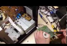
In detail: DIY repair of a t2 tuner from a real master for the site my.housecope.com.
Is your TV, radio, mobile phone or kettle broken? And you want to create a new topic about this in this forum?
First of all, think about this: imagine that your father / son / brother has an appendicitis pain and you know from the symptoms that it is just appendicitis, but there is no experience of cutting it out, as well as the tool. And you turn on your computer, access the Internet on a medical site with the question: "Help to cut out appendicitis." Do you understand the absurdity of the whole situation? Even if they answer you, it is worth considering factors such as the patient's diabetes, allergies to anesthesia and other medical nuances. I think no one does this in real life and will risk trusting the life of their loved ones with advice from the Internet.
The same is in the repair of radio equipment, although of course these are all the material benefits of modern civilization and in case of unsuccessful repairs, you can always buy a new LCD TV, cell phone, iPAD or computer. And for the repair of such equipment, at least it is necessary to have the appropriate measuring (oscilloscope, multimeter, generator, etc.) and soldering equipment (hair dryer, SMD-hot tweezers, etc.), a schematic diagram, not to mention the necessary knowledge and repair experience.
Let's consider a situation if you are a beginner / advanced radio amateur soldering all sorts of electronic gizmos and having some of the necessary tools. You create an appropriate thread on the repair forum with a short description of “patient symptoms”, ie. for example “Samsung LE40R81B TV does not turn on”. So what? Yes, there can be a lot of reasons for not switching on - from malfunctions in the power system, problems with the processor or flashing firmware in the EEPROM memory.
More advanced users can find the blackened element on the board and attach a photo to the post. However, keep in mind that you are replacing this radio element with the same one - it is not yet a fact that your equipment will work. As a rule, something caused the combustion of this element and it could “pull” a couple of other elements along with it, not to mention the fact that it is quite difficult for a non-professional to find a burned-out m / s. Plus, in modern equipment, SMD radioelements are almost everywhere used; The subsequent restoration of which will be very, very problematic.
| Video (click to play). |
The purpose of this post is not any PR of repair shops, but I want to convey to you that sometimes self-repair can be more expensive than taking it to a professional workshop. Although, of course, this is your money and what is better or more risky is up to you.
If you nevertheless decide that you are able to repair the radio equipment on your own, then when creating a post, be sure to indicate the full name of the device, modification, year of manufacture, country of origin and other detailed information. If there is a diagram, then attach it to the post or give a link to the source. Write down how long the symptoms have been manifesting, whether there were surges in the supply voltage network, whether there was a repair before that, what was done, what was checked, voltage measurements, oscillograms, etc. From a photo of a motherboard, as a rule, there is little sense, from a photo of a motherboard taken on a mobile phone there is no sense at all. Telepaths live in other forums.
Before creating a post, be sure to use the search on the forum and on the Internet. Read the relevant topics in the subsections, perhaps your problem is typical and has already been discussed. Be sure to read the article Repair strategy
The format of your post should be as follows:
Topics with the title “Help fix the Sony TV” with the content “broken” and a couple of blurred photos of the unscrewed back cover, taken with the 7th iPhone, at night, with a resolution of 8000x6000 pixels are immediately deleted. The more information you post about the breakdown, the more chances you will get a competent answer. Understand that the forum is a system of gratuitous mutual assistance for solving problems and if you are dismissive of writing your post and do not follow the above tips, then the answers to it will be appropriate, if anyone wants to answer at all. Also keep in mind that no one should answer instantly or during, say, a day, no need to write after 2 hours “That no one can help”, etc. In this case, the topic will be deleted immediately.
You should make every effort to find a breakdown on your own before you get stumped and decide to go to the forum. If you outline the entire process of finding a breakdown in your topic, then the chance of getting help from a highly qualified specialist will be very great.
If you decide to take your broken equipment to the nearest workshop, but do not know where, then perhaps our online cartographic service will help you: workshops on the map (on the left, press all buttons except “Workshops”). You can leave and view user reviews for workshops.
For repairmen and workshops: you can add your services to the map. Find your object on the map from the satellite and click on it with the left mouse button. In the field “Object type:” do not forget to change to “Equipment repair”. Adding is absolutely free! All objects are checked and moderated. A discussion of the service is here.
Message Oleg Bondarenko »16 Jan 2016, 11:23
Repair of T2 tuners in Krivoy Rog: Strong, Trimax.
After repair, a 3-month warranty for a spare part.
Repair time is up to 1 week.
Repair cost: depends on the price of the spare part and the complexity of the work. Before carrying out the repair, the customer is informed about the cost of repairing the T2 tuner.
Phones in signature.
In this thread, write only questions related to the repair.
Unauthorized ad placement - ban and remove all ads and account.
Need help setting up your T2? Write a question on the forum.
Registration takes 2 minutes, the answer to the question is in brackets.
Message ut9ee »18 Jan 2016, 20:12
Since the late 90s of the last century, audio - video technology has evolved greatly. From VCRs and DVD players, CD and MP3 recorders, to omnivorous media players that allowed you to read media files from a USB flash drive. Such devices cost 3-4 thousand in due time.
Now every DVB-T2 receiver can do it. The receivers are quite cheap - from 900 rubles, and in addition to reading media files from a flash drive, they allow you to watch television with digital quality for free, albeit only 20 channels. And everything would be fine if the Chinese, in pursuit of cheap devices, did not put low-quality parts there. I have had cases when in a receiver with a built-in power supply, after 2 years of operation, a small electrolytic capacitor had an overestimated ESR.
Shallow electrolytic capacitor
And accordingly, the receiver did not turn on, after measuring the equivalent series resistance ESR with a meter, and replacing the three-ruble capacitor, everything returned to normal and the receiver turned on. But this, as they say, was just lucky. More often, DC-DC converters burn out in receivers. Sometimes, fortunately for the user who decides to repair the set-top box on his own, stabilizers with 3 legs are installed instead, the replacement is not difficult, but sometimes the boards have unreliable five-legged converters, we will analyze this case. There are 3 of them - small microcircuits in the SOT-23-5 package.
Chip Converter - drawing
They give respectively 3.3 volts required to power the RAM microcircuit, 1.8 volts and 1.2 volts required to power the processor.
Dimensions of converter chip
It is easy to determine where the output of the microcircuit is, even without a datasheet for this microcircuit, the output of the converter is connected by a track with a choke necessary for the operation of the converter. You can familiarize yourself with one of the typical converter circuits by looking at the figure below:
Converter wiring diagram
What if your set-top box refused to turn on, you opened it and, having called, found two or more terminals in a short circuit or low resistance? Such converters, due to the fact that their binding is sometimes individual and incompatible with other types of converters, it is necessary to change them strictly to exactly the same, or in extreme cases to full analogs taken from datasheets.
Converter chip pinout
The wiring diagram, the ratings of the parts, the output current, and of course the output voltage must completely match. I got one of these attachments for repair with a 3.3 volt converter power input punched to the ground. A quick search in the radio stores of our city showed that we have no such microcircuit or complete analogs anywhere else.
Converter to Ali Express Party
And on Aliexpress, they were only in batches of at least 10 pieces, and with expensive paid delivery, which did not suit me. How to be in such a situation? The solution was found and I decided to share it with the readers of this site. Moreover, the output is very low-cost, in terms of the cost of parts in comparison with the purchase of a batch of converters.
Photo converter board
The fact is that for design on arduino and microcontrollers, special small-sized converters, stabilizers are produced in China, immediately with the necessary body kit soldered on the board for their operation. These are AMS1117 stabilizer microcircuits familiar to many electronics engineers.
Stabilizer ICs AMS1117
These microcircuits are produced as adjustable, which is unnecessary for us in this case, and with a fixed voltage at the output, but we are interested in voltages of 1.2, 1.8, 3.3 volts. For all these voltages, ready-made converter shawls are on sale on Aliexpress, based on these stabilizers. How can you distinguish between converter boards, if, for example, you bought them earlier and forgot what voltage they are?
On the case of microcircuits, in addition to the name of the model, stabilizers for a fixed voltage, it is sometimes written the voltage that will be at the output of the converter, that is, the same 1.2, 1.8, 3.3 V we need. How to place these converters in the receiver case? They will not take up much space, I would not think long, MGTF soldered to three of the contacts on the converter board, there are 4 of them: input plus power supply, output plus power supply, and two contacts common for input and output ground.
Why we use three contacts out of four I think it is clear. How can we check ourselves whether we found the correct pinout of the microcircuit if a Chinese datasheet found for example raises doubts? Call the output indicated by the datasheet Vin, often if the set-top box comes with an external power supply, it is directly connected to the power socket. Also, between the ground and the power input, an electrolytic capacitor is often installed on the board, at 220 μF x10 or 16 volts.
Condenser 220 x 25 volts
The plus of the capacitor is connected to the power input of the converter microcircuit. What if you do not know for what voltage this converter was at the output, that is, for what voltage do you need to buy the converter? You can try after dismantling the burned-out microcircuit and cleaning the contacts on the board from solder, supply power to the receiver and measure the supply voltage on the two remaining converters. And determine the voltage at the output of the remaining microcircuit by the elimination method. Solder this burnt-out converter using a hot air gun, or by applying a drop of solder, Rose or Wood's alloy to all contacts, and heating them quickly alternately with a 25-watt soldering iron.
If you are sure that the converter has burned out and are not afraid to burn it with the high temperature of the tip, during dismantling, you can apply a little POS-61 ordinary solder to all the contacts and alternately heat the 40-watt terminals with a soldering iron, trying to move the microcircuit. If, after soldering, it turned out that the short circuit was “underfoot” on the board, and not in the microcircuit, you need to finally make sure of this, clean the contacts of the old soldered converter from solder using a dismantling braid, applying an alcohol-rosin flux to the contacts with a brush (SCF).
SKF alcohol rosin flux
Then just put the braid on top of the contacts and heat the leads over the braid with a soldering iron. The solder will go to a clean braid. The tip of the braid can even be dipped in alcohol rosin flux for better absorption. As the solder is absorbed, the end of the braid should be cut and repeated from the beginning. The same should be done with the contacts on the board left after the soldered converter.
There, as usual, we will have "snot" from the solder applied during dismantling - they must be removed. Then you can solder the MGTF wire connected to the contacts of the converter, finding by the datasheet for this microcircuit where we have the power input, where is the output, and where is the ground. It will be possible to check, as I wrote above, the contact connected to the ground by the minus of the power supply, we can call by touching either the polygon on the board, or if you are a beginner and are not sure of the correctness of the dialing - the metal body of the USB connector.
After everything has been soldered, do not rush to turn on the attachment to the network, wash off the traces of the flux with alcohol, especially if you never know, used a weakly active flux, which in this case is a prerequisite for the long operation of the device. Then look under a strong magnifying glass or take a picture with a phone with a good camera and make sure not to put "snot" on the adjacent contacts, as they are there quite close to each other.
Multimeter in audible dial mode
To be completely sure that there is no short circuit, or if it was not possible to find a strong magnifying glass, ring all adjacent contacts relative to each other for a short circuit with a multimeter in the audible dial mode. All these procedures with replacing the converter make sense only in one case - if, after checking the datasheet, you did not find a short circuit of the power input pins to the power output, since in this case your processor or RAM microcircuit has already burned out due to the supply of an overestimated supply voltage.
DVB-T2 tuner board processor and memory
Which, of course, is sad, since then it will not be realistic to fix it either at home, or even in a good workshop, due to the laboriousness of the repair and its high cost - higher than the cost of a new attachment, it will not make sense.
Any more or less trained radio amateur can easily cope with this repair, and due to the low cost of the board for replacing the converter, it can be recommended as a means, albeit a "collective farm", but a very budget solution, in the absence of extra funds from an economical radio amateur for purchase of a new set-top box. Or there is simply a desire to prove to oneself that the repair of complex digital equipment is quite realistic sometimes to be carried out on our own. Successful repairs to everyone! AKV.
Hello everyone. Today is a small note about the repair T2 tuner Trimax TR-2012HD.
When turned on, the power indicator blinked either green or red, after a while the tuner could turn on, but after a minute it hung up.
Trimax TR-2012HD malfunction manifestation
The tuner is equipped with a power supply unit for 12volt, power 1A.
The first thing I decided to do was check it out. Having measured the voltage at the output, it turned out that it jumps from 11.3 to 12.3v... It became clear that the power supply itself was faulty.
Since the power supply is not collapsible, I used a powerful knife to open it. Putting the block on the table, the knife put it in the slot of the soldering of the two halves, and then hit the knife with a small hammer. The body split into 2 halves.
Upon visual inspection, I noticed no swollen capacitors, but they were not noticed. As the PSU starts up, it is clear that the reason for its malfunction is a loss of power, and the cause is usually capacitors. First of all, I decided to diagnose the network capacitor 22mkf at 400v.
The voltage on it should be of the order 300 volts, but in fact it was 235c.
Mains capacitor voltage
This indicates that the capacitor is hooked and needs to be replaced. After replacing the capacitor, the voltage across it was 319c.
Voltage on the mains capacitor after replacement
After that, the tuner started working. The output voltage was stable 12.3 volts .
Received for repair T2 receiver, "no signs of life", we open and find a breakdown. Do-it-yourself T2 repair, fast and cheap
POWERFUL ANTENNA FROM TWO BEER CANS FOR DVB T2 Tested The signal catches 90% I didn’t even expect. SO THE SIGNAL WAS THE SAME ON 20 CHANNELS ONE BANK SHOULD SUPPLY FROM PEPCOLA OR CUT IT UP TO 12 cm. Then the signal level will be 86% and more than 86%. .The short jar should be placed on the Cable Shield.
The defect is not uncommon, even with completely new tuners. Strong SRT8500 .
The green LED is on and there are no more signs of life. Does not respond to buttons, does not produce picture and sound.
It is useless to flash. In this case, there is a dump of balls under the processor.
The only difference is in temperature.
It is treated by warming up at a temperature of about 280 degrees... Perhaps it was possible to try lower, but it was necessary to blow from a certain distance with a nozzle about 1 cm in diameter.

Try to be careful not to deform the plastic of the card capture reader.
Warmed in total for about 5 minutes with bottom heatinguntil the flux begins to evaporate profusely.
The radiator did not take off... I was afraid that it would be removed along with the processor. The tuners are nasty. Pensioner free version. They die everywhere and often. In this instance, the back of the board already had traces of flux washing, despite the fact that I tore off the seal personally.
After a smooth cooling down, the tuner turned on almost immediately and was updated. It is better to turn on with a pre-installed antenna to avoid problems with updating.
Updating in such tuners is quite an interesting thing. You cannot refuse to update the software. For me, this means that you are not in control of the tuner, and you will watch what is interesting to your uncle with money, and not to you personally.
I think the people are still waiting for a big gift from our generous handlers in the form of paid channels. No wonder the tuner has a place for a card.
Tuner suicide is not the only cause of death. Power engineers also help. A couple of tuners did not turn on after a voltage drop.
In one case, it was enough to replace the quietly deceased PWM controller U901 - TNY176PN on the other the same and the device started.
The scheme is clickable and readable.
The second was not without special effects. A pair of diodes, a fuse, and a network capacitor are attached to the microcircuit 10 microfarads x 400 volts.
Chip TNY176PN has analogues and can be easily changed to TNY275PN without any alterations.
On the example of MDI DBR 1001 DVB - T2 set-top boxes, possible repair by handy and affordable ways. Links below. ePN cashback.
Satellite and digital television in the Primorsky Territory!
The most common and easily repairable malfunction of DVB-T2 digital television set-top boxes is just one.
world vision t 56 there is no signal, https://my.housecope.com/wp-content/uploads/ext/2995/world-vision-56-net-signala-remont/ it does not need to be thrown out, most likely it can be removed.
Digital TV T2. Repair of the STRONG 8500 tuner after a power surge. Does not turn on. Repair advice.
In this video I will show you how to fix this problem in t 2.
So buvaє, in the practice of repairs there is an order that doesn’t fit into a repair. A lot has been stained for an hour.
Any product from China “Aliexpress.com” https://ali.pub/uo612 Any product from China “Gearbest.com” Save on ePN purchases.
Microcircuit TNY176DG: Tools and consumables in the video: - aluminum tape: - soldering.
The TV set-top box (DVB-T2 receiver) displays the word “boot”, and does not display the image on the TV. Main: H-DVT-14503 Tuner: MXL603.
TRIMAX TR-2012HD is not included https://ali.epn.bz/?i=bc399 Refund 8.5% from AliExpress VK Group https://ali.pub/7ax1u Any.
parts of the impulse power supply burned out.
What to do if the DVB-T2 receiver does not turn on, or, as it is called in another way, a digital television set-top box.
Reflect mini dvb t2 repair after 12 V is connected to it. power supply unit https://my.housecope.com/wp-content/uploads/ext/2995/dvb-t2-pristavka-remont-reflect-.
Rolsen RDB-530 repair is not included. Useful: How to determine what voltage was at the output of the microcircuit.
Received for repair T2 receiver, "no signs of life", we open and find a breakdown. Do-it-yourself T2 repair, fast and cheap
POWERFUL ANTENNA FROM TWO BEER CANS FOR DVB T2 Tested The signal catches 90% I did not even expect. SO THE SIGNAL WAS THE SAME ON 20 CHANNELS ONE BANK SHOULD BE SUPPLIED FROM PEPCOLA OR CUT IT UP TO 12 cm. Then the signal level will be 86% and more than 86%. . A short can should be put on the Cable Screen. Help Materially Send 100 rubles to the Sberbank Card 2202 2001 2083 6588 Here is another Powerful antenna
After a voltage drop, the receiver failed. Interestingly, the fuse is still intact. After replacing the burnt out elements, the receiver started up, but there was no signal, squares fell, the signal scale lived its own life. The problem turned out to be in the capacitor in the 450V 47μF power supply module. After replacing it, the signal appeared and was stable.
How to connect an antenna cable to the F connector with your own hands when connecting a TV to a TV antenna. Channel: DIY repair -
So buvaє, in the practice of repairs there is an order that doesn’t fit into a repair. It took a lot of an hour, but the result is zero! Dosvid, zvisno, otrimano, ale the cost of spending an hour that radio parts.
Received for repair T2 receiver, "no signs of life", we open and find a breakdown. Do-it-yourself T2 repair, fast and cheap
We test the attenuation in a copper versus bimetal cable, Using the example of a Finmark cable, we carry out an attenuation test on an honest copper cable, and a bimetal Help kiwi channel wallet 380939291223, private card 5168755429929652 Other satellite TV videos on my channel - How to fix a tuner with your own hands FOR ADVERTISERS AND CONTACT THE AUTHOR SUBSCRIBE! our group
POWERFUL ANTENNA FROM TWO BEER CANS FOR DVB T2 Tested The signal catches 90% I did not even expect. SO THE SIGNAL WAS THE SAME ON 20 CHANNELS ONE BANK SHOULD BE SUPPLIED FROM PEPCOLA OR CUT IT UP TO 12 cm. Then the signal level will be 86% and more than 86%. . A short can should be put on the Cable Screen. Help Materially Send 100 rubles to the Sberbank Card 2202 2001 2083 6588 Here is another Powerful antenna
After a voltage drop, the receiver failed. Interestingly, the fuse is still intact. After replacing the burnt out elements, the receiver started up, but there was no signal, squares fell, the signal scale lived its own life. The problem turned out to be in the capacitor in the 450V 47μF power supply module. After replacing it, the signal appeared and was stable.
How to connect an antenna cable to the F connector with your own hands when connecting a TV to a TV antenna. Channel: DIY repair -
So buvaє, in the practice of repairs there is an order that doesn’t fit into a repair. It took a lot of an hour, but the result is zero! Dosvid, zvisno, otrimano, ale the cost of spending an hour that radio parts.
Orton 4050c does not include PSU repair smps888 ver 1.4 https://ali.pub/3s5fy AM-22A https://ali.pub/7ax1u Any product from China https://ali.epn.bz/?i=bc399 Return 8 .5% from AliExpress Group VK
Simple repair DVB T2 receiver D COLOR DC1001HD does not turn on
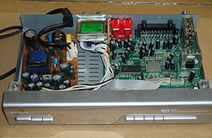
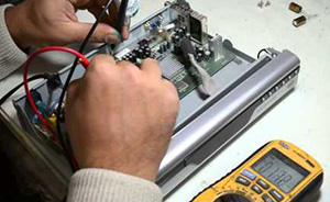
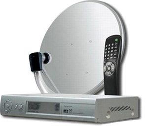
The need to repair the receivers can be caused by a failure in the software, which is located on the non-volatile flash card. However, its certain isolation does not at all guarantee the absence of failures, and a complete flashing of the device may be required. This repair procedure for T2 tuners and other types of similar devices requires a professional approach, the presence of certain knowledge, skills and equipment. Each model needs a different software version. By the way, a breakdown of the memory microcircuit itself can become a reason for repairing the tuner.
It is worth noting that you should look for faults not only in the device itself, but also in the remote control. Remotes are much more likely to fall, which can damage the crystal resonator. Also, due to low-quality components or their wear and tear, T2 or any other signal repeater may need to be repaired. To find out for sure the cause of the breakdown of the device, you need its full diagnostics, and for this you need special equipment.
I'll start with the antenna, it's completely homemade. Everything ingenious is just to the point of idiocy 🙂
Do not forget to like and subscribe, ladies and gentlemen. There will be many more interesting things!
Hello. You have a photo of this antenna on the car, how the cable was laid, as it shows in motion. (Just don't write that you need to follow the road). I want to do it for passengers, but you can just listen to the music of TV.
Hey! It seems that it was somewhere in the logbook, I put it on the right windshield pillar. In motion, it sometimes stutters, I think we need to rely on it to be longer or put it on the street and you can do it 🙂
Thank you, you need to experiment too.
And if you make more than 22 cm, then will TV programs from aliens be broadcast?))))
What kind of TV do you need? I understand vidos to watch, or to make a reversing camera, but a TV is not needed for a gift =)
You need to calculate the length, but through the tuner you can watch vidos
So soon you will watch TV shows in motion, you will turn into a granny Pavelentius)))
No, I'll be Malakhov and watch the voice 🙂
I thought you would start right away with Dom - 2)))))
Then the khan will quickly come to your monitor, as if throwing tomatoes with rotten eggs)))))
Satellite TV is not the last in the entertainment industry. And this is facilitated by the inexpensive price of equipment and an extensive list of channels. But all the joy can descend to "no" if the satellite TV receiver does not turn on.

This article will provide simple and practical ways to identify a faulty part in a tuner power supply. Although the methods are simple, their use in most cases allows you to repair the power supply of a satellite TV receiver with your own hands.
So, if your satellite TV receiver of the model: Gione, Cosmo Sat and the like has stopped working, then do not rush to worry, perhaps everything is not so bad. Try to find the cause yourself without the help of specialists.
What might you need? Multimeter, dial tone, soldering iron and a little patience.
We remove the cover of the device, and we see a free-standing module. This is a switching power supply. To start troubleshooting, remove it by unscrewing the screws and disconnecting the connector on the system board. Now the board is in front of us.


The first thing to do with the board is to visually determine if there are damaged (swollen) capacitors and other circuit elements. Often it is for this reason that the satellite TV receiver does not turn on.

If no damage is visible, then it is necessary to check the integrity of the cord and fuse. We put a dial on the ends of the fuse, and by the reaction of the device we determine its integrity.

Now, if in the circuit, when turned on, there is a short circuit, then the lamp will simply light up at full heat, without causing any harm to the circuit. If the lamp does not light up when turned on, we take a multimeter and measure the voltage across a large capacitor of 47 μF * 400 volts.


The diodes have been replaced, now we turn it on again and measure the constant voltage across the same capacitor. It should be, as mentioned above, about 300 volts. If so, then the next step in the diagnosis is to measure the alternating voltage on one of the primary windings of the transformer. How to do this can be seen in the photo below.

When the device shows the presence of a pulsating AC voltage on the primary winding, it is necessary to immediately measure the DC voltage at the output of the unit.


If you turn the plug with the slots towards you, and measure from left to right, then the voltages should be as follows:
If there is no voltage, then we do the same operation with the diodes of the secondary circuit, as described above. Having identified the faulty one, we replace it. Note the larger diode. It is labeled SR-360 and the like. He most often fails. Replacing it, you can solve the problem when the satellite TV receiver does not turn on. Again we measure the voltages at the terminals.
If this method did not give anything, then most likely the microcircuit in the primary circuit, which plays the role of a high-frequency alternating voltage generator, "flew out". But, as practice shows, this rarely happens.
That's all that I wanted to tell you about the repair of the power supply unit of the satellite TV receiver. Successful renovation.
| Video (click to play). |
49,136 total views, 56 views today


