In detail: do-it-yourself akira TV repair power supply from a real master for the site my.housecope.com.
A collection of repair tips and ready-made solutions, hundreds of times, successfully used in the repair of TVs from this company:
Akira СТ-1410 (11AK20S2 chassis) the colors of the image were distorted and had unevenness across the raster field: above - purple shades, in the middle - shades of yellow, below - red
Checking the TN801 thermistor showed its serviceability. however, soot was found on the chassis underneath. After removing it and installing the old thermistor in place, the colors of the images were restored.
If the TV does not show any signs of life, then first you need to look into the power supply. First of all, you need to check the integrity of the power plug and make sure that the strap enters the power supply. Believe it or not, this is one of the most common problems in the practice of repairing various household appliances, not just TVs. Then we check and ring the fuse on button, if we see a blown fuse, in no case put a larger one at face value.
To check the TV power supply directly, we turn off the load, which is usually the horizontal output stage, and cut a 220 V light bulb to the vacated contacts. Next, we check the input circuits, the mains rectifier, the filter capacitor that stands after the mains rectifier, and the powerful transistor of the power supply. If the lamp does not light up at all, you need to look for an open circuit in the mains rectifier, filter, in the capacitor, which is immediately after the mains rectifier.
Often, in the event of a malfunction (breakdown) of the electrolytic capacitor connected after the mains rectifier, the current-limiting resistor or filter choke burns out, as well as the rectifier diodes. If, when turned on, the lamp replacing the fuse lit up and immediately went out or began to glow faintly, and the lamp connected instead of the sweep circuit lit up, then we can assume that the power supply is working, and further adjustment can be made without a lamp.
| Video (click to play). |
If, however, the lamp connected instead of the scanner does not light up, then you need to look for a malfunction in the power supply. First of all, measure the voltage across the largest capacitor of the power supply (this is usually the capacitor included at the output of the mains rectifier). The voltage across it should be somewhere around 300V. If it is much lower or absent altogether, then the fault must be looked for in the mains rectifier, circuits from the mains to it, as well as in this capacitor itself.
For example, if it loses capacity, the voltage at the output of the rectifier will be pulsating, and the multimeter will show this constant undervoltage. If the voltage on the "largest capacitor" of the power supply is normal, then you need to check the pulse generator, the powerful output transistor, as well as the secondary circuits.
Troubleshooting Line Scanner... After making sure that the power supply is in good working order, we restore the connection in the voltage supply circuit to the horizontal scan, removing the lamp that was used as a load. Again, we connect the TV to the mains through a 150 W lamp, that is, we use it instead of a mains fuse. If the horizontal output stage is working properly, then the lamp, when turned on, will light up for a few seconds and then go out or glow dimly. If, when turned on, the lamp flashed and continues to burn, you need to make sure that the line scan output transistor is working properly. If it is working properly, but there is no high voltage, check the presence of control pulses at the base of the horizontal output transistor.If there are pulses and all voltages are normal, then the line transformer is most likely faulty.
Sometimes a line transformer malfunction is immediately visible by its strong heating, it is very difficult to assert with full confidence whether the TDKS is serviceable, only by external signs is very difficult. In order to determine this exactly, you can proceed as follows. Disconnect the TV from the network. Apply rectangular pulses with a frequency of several kHz of small amplitude to the collector winding of the transformer (you can use the oscilloscope calibration output). We also connect the oscilloscope input there. With a working transformer, the maximum amplitude of the obtained differentiated pulses should be not less than the amplitude of the original rectangular pulses. If the transformer has short-circuited turns, then short differentiated pulses with an amplitude much less than the original rectangular ones will be visible.
This method can also determine the malfunction of transformers of network switching power supplies, as well as other transformers, chokes. It is not necessary to solder the transformer, but of course, you need to make sure that there is no short circuit in the secondary circuits.
Vertical scan malfunctions... With a working line scan, at least a thin horizontal stripe should be on the screen, and with a working frame scan - a full raster. If there is no raster and a horizontal strip is visible on the screen, adjust the accelerating voltage (Screen) on the line transformer to reduce the brightness of the screen so as not to burn through the phosphor of the kinescope, and only then proceed to troubleshooting in the vertical scan. Troubleshooting in the vertical scan unit should begin with checking the power supply of the master oscillator and the output stage. Usually, the power to these stages is taken from a rectifier, which receives voltage from the winding of a line transformer.
The supply voltage of these stages is 24. 28 V. There are circuits with a bipolar supply voltage or with two different voltages, for example, 8V and 26V to power the master oscillator and the output stage. The voltage is supplied through a limiting resistor, which should be checked first. Frequent malfunctions in the frame scan circuit are breakdown or breakage of the rectifier diode and failure of the frame scan microcircuit. Turn-to-turn closure in personnel deflecting coils is much less common. If you suspect a deflection system malfunction, it is better to check it by temporarily connecting a deflection system that is known to be in good working order. It should be controlled with an oscilloscope, observing the shape of the pulses directly on the frame coils.
Malfunctions in the circuit of the radio channel and video path.
Here's a malfunction - the scan is working, the screen is lit, but there is no image. In this case, the faulty node can be identified as follows. If there is no sound and image, the malfunction should be looked for in the radio channel (tuner, video processor). If there is sound, but there is no image, the malfunction should be looked for in the video amplifier or video processor circuit. If there is an image and there is no sound, it is most likely that the audio amplifier is faulty.
Still quite often there are problems with the circuit for connecting external devices - input, output audio and video. Here, after all, various switches are used, and there may be a malfunction in them, or, for example, there may be no sound when receiving television, but there is sound when working with a DVD player. Then the matter may be in the switching circuit or due to a malfunction of the capacitor, through which the sound signal from the output of the radio channel goes to the preliminary ultrasonic frequency converter. After checking the supply voltage of the radio channel, you need to supply video and audio signals through the low-frequency input (you can use a TV signal generator or a DVD player).
If there is no image, you should use an oscilloscope to trace the passage of the signal from the source from which the signal was sent to the cathodes of the kinescope or, if the audio channel is faulty, to the speakers and, if necessary, replace the faulty element. If, after the signal was applied to the low-frequency input, the image and sound appeared, and you are sure of the working order of the switching circuit, then the malfunction should be looked for in the cascades of the radio channel. In the case of a lack of sound when receiving television, you should check this on different channels. Perhaps the TV is working properly, but the sound standard of the selected TV channel does not match the capabilities of this TV. This is especially true if the TV is old, it may not support different broadcasting standards.
When checking the video processor, it is necessary to send the IF signal to the IF filter input from the generator or from the tuner output of another TV. If the image and sound did not appear, we check the signal path with an oscilloscope and, if necessary, change the video processor (when replacing the microcircuit, it is better to immediately install the socket). If there is an image and sound when the IF signal is supplied from another source, then the malfunction should be looked for in the tuner or in its harness. First of all, you need to check if the tuner is receiving power. Check the integrity of the key transistors through which the voltage is supplied to the tuner when switching ranges.
Check whether the signal from the control processor arrives at the bases of these transistors, check the magnitude and range of the tuning voltage, which should change within 0.31 V. If the tuner is digital, the tuning voltage will not change, since the circuit located in the tuner does this controlled by the controller via the digital bus. In this case, you should check the presence of pulses in the digital bus, as well as their arrival at the tuner inputs.
Of course, it is not always possible to apply an IF signal to the input of the video processor. But, if so, then you can not do this, but check the tuner strapping, the supply of power to it, the tuning voltage.However, it is not difficult to make the IF generator on your own, just take a working analog tuner and assemble a circuit for its strapping - for power supply, variable resistor for adjusting the tuning voltage. Connect all power, antenna. And there will be a ready-made inverter generator. If the tuner is faulty, it needs to be replaced with a new one, repairing the tuner is difficult and not always successful, especially if you are a novice TV technician.
Repair of the control board. When repairing the control controller, you still need to use the diagram of this TV and the reference data for this controller. A malfunction in this scheme can manifest itself as follows: the TV does not turn on, does not turn off, does not respond to signals from the remote control or control buttons, does not adjust the volume, brightness, contrast, saturation, tuning to channels, switching AV / TV, there is no saving settings in memory, no indication of control parameters. If the TV does not turn on, we check the presence of a supply voltage on the processor and the operation of the master oscillator. After that, you need to determine whether the signal from the control processor comes to the TV turn-on circuit from standby mode.
To do this, you still need to get a TV circuit. It should be noted that on the control processor, the power-on signal is designated either Power or Stand-by. If a signal comes from the processor, then the fault should be looked for in the switching circuit, and if there is no signal, the processor will have to be changed. If the TV turns on and reacts to buttons, but does not respond to signals from the remote control, then, first of all, you need to check the remote control itself. You can check it on another TV of the same or similar model. To test the consoles, you can make a simple device consisting of a photodiode connected to the oscilloscope input, the sensitivity of which is set within 2.5 mV. The remote control should be aimed at the LED from a distance of 1.5 cm.Bursts of pulses will be visible on the oscilloscope screen if the remote control is working properly. If there are no pulses, the remote control is faulty. In this case, you need to check its power supply, the condition of the contact tracks and contact pads for the buttons, the presence of pulses at the output of the remote control microcircuit, the health of the transistor or transistors and the health of the emitting LEDs.
Very often, when the remote control falls, its quartz resonator breaks down or its output simply breaks off, since the resonator is relatively heavy, and its outputs are thin and soft. If the remote control is working properly, you need to trace the signal flow from the photodetector to the controller. If the signal reaches the controller, and nothing changes at its output, it can be assumed that the controller is faulty. In many modern TVs, the controller and the video processor are on the same microcircuit. If the TV is turned on from the remote control and the pulses are received, but the operational adjustments do not work, you need to find out with which output the controller controls this or that adjustment (volume, brightness, contrast, saturation). Next, check the paths of these adjustments, right down to the actuators. The controller issues control pulses with a linearly varying duty cycle, arriving at the actuators, these pulses are converted into a linearly varying voltage.
In circuits in which the control controller and the video processor are in one microcircuit, many control circuits can be inside this common microcircuit, that is, they cannot be analyzed and repaired. Nowadays, most often, the controller controls the entire TV circuit via a digital bus. In this case, there are no separate pins, for example, for adjusting the volume or contrast. All this control is carried out via one digital bus, suitable for the video processor, tuner, audio processor, input switching device. Lack of memory for settings and adjustments is usually associated with a malfunction of the electrically reprogrammed ROM. Most often it is a separate small microcircuit. Data exchange between the control controller and the memory microcircuit is carried out via a digital bus. If the memory does not work, first of all, you need to check the supply of power to the memory chip.
Often, its supply voltage differs from the controller supply voltage, therefore it is supplied to it through a separate parametric stabilizer, the zener diode of which may fail. And such a microcircuit is connected to the digital bus through resistors - voltage dividers, which are needed to match the logic levels of the controller and the memory microcircuit. There may be a malfunction here too. After replacing the memory chip, you need to make the appropriate settings in the service menu of the TV, therefore, you must first find the service instructions for this model (or chassis) of the TV, at least a table of the initial memory settings.
The TV was brought from another workshop with a faulty power supply. Earlier, before a breakdown, sometimes it turned off.
An autopsy revealed a swollen capacity for the line power supply, MC44604P with no signs of life, instead of the Q810 thyristor, 2SA1013 was stuck. After replacing the MC44604P and the capacity, the power supply produced + 10v, but sometimes it started up for a few seconds before the operating voltage. The reason turned out to be in the chip resistor R809 1 kOhm, when heated with a soldering iron, the tin came off one side of the resistor and no longer adhered. After installing a conventional resistor, the power supply began to normally enter the operating mode. Since I did not find a thyristor on sale MCR22-6 installed MCR100-6. After the repair, the power supply gave out 114.8v in the working one, and 13.3v in the duty one.
Dim screen with changed colors. As if there is not enough brightness signal. Probably there may be other manifestations associated with the video channel. The defect is interesting because everything seems to be normal. A series of repairs due to the wilting of the C 47x50V in the power supply unit and the replacement of a zener diode with 12V 1W, etc.children the device passed, + 115V is normal and does not bounce into the bowl. dir. A somewhat underestimated voltage from a 12V 1W zener diode (in AKIRA ZD402), only about + 10.5V, brought me into thought. It turned out that the bursting resistor supplying voltage from 3 legs of the TDKS to the power supply rectifier of the zener diode increased its resistance from less than one Ohm to 5 Ohm !! As a result, the rectified voltage dropped below 12V instead of the prescribed 14-16V. This is the second time we meet. Therefore, I recommend that after a standard repair when + 115V is overestimated, check the resistor R443 (in AKIRA) R421 (in AKAI) if its value has increased.
After eliminating the standard set of faults - with aut. setting skips all stations and, accordingly, there is no sound. Adjusting the circuits, replacing the capacitors in them did not change the situation. I must say that a comrade of the owner of the TV had already tried to repair it before me. After titanic efforts, it turned out that this "craftsman" had replaced the capacitor (hinged from the side of installation from the "-" capacitor C321 to the ground). The native has a nominal value of 4.7n, and he bet 22n. As a result, on the 13th leg of the C68241Y (ident) probe, 5 volts did not appear at any circuit settings! After the replacement, everything was set up like clockwork. And the owner retained its native capacity (it was given away as faulty).
The vertical dimension is small, about 5 cm. Replacing the LA7830 and electrolytes did not work. Open capacitor 1 nF at pin 5 of the frame microcircuit.
Very similar to FUNAI. Defect when switching on, a squeak is heard. The reason - the output line transistor 2SD1556 burned out due to the increased voltage from the power supply unit (capacitors in the primary circuit dried up). After replacing the electrolytes and the transistor, the TV worked, but there was no color in the SECAM. The cause of this malfunction was the decayed terminals of the color identification coil.
Does not turn on, beeps, + B is understated. With a load - a 60W lamp, the power supply unit outputs 118V - i.e. the norm. NOT - whole. TESTING out. cascade of horizontal scanning lowered + B = + 15V revealed the following. The pulses on the TDKS legs are sometimes normal, sometimes they sit down - at this moment the current consumption along the + V circuit (that is, + 15V) rises to 300mA. If you turn off the OS, it bounces back. When examining the OS, I noticed the conclusions of the KK and SC folded among themselves - they stuck together and began to contact. He pushed the ends apart, again soldered the ends - and the OS is saved. I turn on the TV, a high appears - and then a surprise awaits! The I577 LA7830 is passing away right before our eyes. I had to replace her.
This secret proves that it is much easier to find a defect in the lowercase output circuits when the + V supply is too low. Plus, the power elements remain intact.
There is no general synchronization, the suspicion fell on the STV2118 video processor, it is good that it was not available, the oscilloscope began to watch the power supply at 9v, strong ripple dried C300 470.0x35v.
Fault: there are vertical stripes (pillars) on the screen, there is no sound. The capacitor C637 is out of order (112 volt filter after the choke and relay). Ripple penetrated the horizontal scan and secondary power supplies, which is why the power switch of the sound microcircuit did not turn on.
Fault: according to the owner, it does not turn on after 1 year of operation. When checking, there is a standby mode, but it is worth turning on, the LED goes out (it seems like it turns on), there is sound, but there is no raster. I checked the power supply. All voltages are normal except for the power supply of the pre-output line scan stage. It is removed from the power supply of the output stage of the horizontal scan through the R629-3.3kOm resistor (5W) and goes through the winding of the swing transformer to the collector of the pre-output transistor. This same resistor periodically went into a break. The dial tone was defined as absolutely serviceable. I put ceramic 3.3 kOm (5W). Just in case, I hooked a radiator for the resistors, as it heats up decently. I did not find a scheme for it. Suitable from ERISSON (chassis 3S10).
Fault: No sound. R640 breakage with 0.68ohm and, as a consequence, failure of one of the two LA4285s, a frequent defect in those who use headphones.
Fault: complaints about random switching, switching to AV, floating settings - well-known "glitches" of the processor. Prots - ST92T195D7B1, memory 24С08. The owner is advanced, he was told that the processor is to blame, he "lost" it. After which, as he claimed, the TV worked for an hour and a half without any problems. My actions. At the time of arrival, the TV worked fine. An attempt to provoke a percentage by heating with a soldering iron is unsuccessful.I notice that its 5 V power supply is actually about 5.7 V. In the Q004 2SC2703 parametric stabilizer in the base of the transistor, the 5.6 V ZDO56 Zener diode is supplemented with a serially connected ordinary diode for an incomprehensible purpose (this is sometimes done for thermal compensation). Moreover, this is not provided on the board, the installation is hinged, that is, the post-design revision. Here are the extra 0.6-0.7V. This would be understandable if Q004 were composite (Darlington). In general, removing the diode gave 5.06 V at the control point, which corresponds to the inscription on the board + 5V C. The TV was then driven and driven for 2 days, until everything is OK. Approx. This diode is seen in other devices with a similar chassis. Maybe they really planned to use a "compound" in the stabilizer, and then changed their minds? And yet - perhaps processors of this type will lend themselves well to "roasting".
Fault: two devices in 2 days - vertical stripe. Burnout of the output of the line coil L301 and failure of the parallel R325 1KΩ.
Fault: the power supply unit does not start, we change the standard set of STRG6653, an optocoupler (better than PC120), 2SC1815 on an optocoupler, sometimes the R610 resistor by 680 ohms flies out. There were returns with the native optocoupler, there were no problems when installing the PC120. Also, in this model of any diagonal, memory often flies out. Entering the service Press from the remote MENU, then again MENU, Q.VIEW, MUTE.
Good luck with the repair! Visit our Forum.


The following are general guidelines for troubleshooting and fixing installation problems.
Vestel VR54TF-2145 (11AK30A4 chassis). When you turn on the TV from
standby mode, the delay in starting the horizontal scan is about half a minute or more if the TV has been turned off for a long time.
The capacitor in the base circuit of the C613 10.0 x 63V line scan transistor turned out to be faulty.
Often, malfunctions are repeated in the same TV models, so the defect may coincide with the list below and it will be easier for you to fix your faulty TV.
Any modern TV has a switching power supply.
The power supply is a whole unit designed to provide the TV with supply voltages of a certain power required for the normal functioning of the electrical appliance.
When the impulse unit is faulty, all sorts of malfunctions of the television receiver are observed, including the fact that it does not work at all or stops turning on.
The power supply can be in the general scheme of the TV or in the form of a separate module.
Power supplies are unique to each TV, each with its own circuitry. But their performance is equally negatively affected:
- violation by the owner of the operating rules (especially the temperature regime),
- relatively simple schemes,
- unprofessional equipment repair.
Malfunctions typical for most power supplies:
- Blown fuse.
- The power supply does not start, there is voltage at the rectifier, the key elements are working properly.
- The power supply does not start because the protection is triggered.
- The power (key) transistor burns out.
- Undervoltage or overvoltage in primary or secondary circuits.
Obviously, only an experienced TV technician can understand the breakdown and repair the TV.Self-repair is highly undesirable, however, it is possible.
If you have some experience, all the necessary knowledge and tools (in particular, a multimeter and a soldering iron), try to fix the TV receiver.
- Turn off the TV (remove the plug from the socket).
- Discharge the high voltage capacitor.
- Remove the board from the TV case.
- Inspect the board (visual diagnostics).
- Check resistors, capacitors, diodes, transistors, etc. with a multimeter.
- Examine the back of the board. Check for cracks, breakdowns between the tracks, the reliability of the soldering of the parts.
- darken,
- crack
- the quality of the soldering of the leads deteriorates.
If all this is noticeable visually, it makes sense to change the resistors for new ones with a deviation from the original no more than plus or minus 5%.
If outwardly nothing is noticeable, you should check the resistors with a multimeter. The resistor is defective if resistance = 0 or ∞.
Defective electrolytic capacitors externally swollen. Their capacity is also checked. Permissible deviations are plus or minus 5%.
A working silicon diode has a resistance in the forward direction of 3-6 kOhm, and in the opposite direction - ∞.
To measure resistance, you need to remove the diode. For testing, the multimeter is set to the resistance measurement mode with a limit of 20 kΩ.
The second option for checking with a multimeter without unsoldering the diode. In this case, the multimeter must be set to the voltage drop measurement mode (should be up to 0.7 V). If the multimeter shows 0 or near zero, the diode will still have to be removed and checked again. If the readings do not change, there must have been a breakout. Part replacement required.
Bipolar transistors are tested in both directions (forward and reverse) at the junctions:
Testing involves measuring the voltage drop across the transistors. It is also important to check that there is no breakdown in the collector-emitter junction.
Serviceable transistors behave like diodes, defective ones need to be checked completely - the entire "strapping":
To check the supply voltages of the switching power supply, you will need:
- his scheme,
- two incandescent bulbs ≈100W.
- Using the scheme, find an exit to the line scan stage.
- Disable output.
- Connect the incandescent lamp.
- Connect the power supply through the second lamp.
If the lamp comes on and glows brightly, the power supply is defective. If the light comes on and goes out or shines weakly, the input circuits of the power supply are working properly.
To determine which element is broken (which is why the light is on), you need to refer to the diagram.
The verification voltage measurement is carried out with a connected lamp on the B + load. The diagram indicates what the voltage should be. Usually it is 110-150V. If it is appropriate, the power supply is working.
If the voltage is increased (200V), check the elements of the primary circuit of the power supply. If lowered - secondary circuits.
All faulty parts are soldered, new ones are soldered in their place.
Remember! It is impossible to repair the TV power supply yourself without knowledge and experience. More importantly, handicraft and amateur repairs are a direct threat to health and even human life!
It is no secret that a breakdown of a television receiver can ruin the mood of any owner. The question arises, where to look for a good master, do you need to take the device to a service center? You need to spend your time on this, and what is important - money. But, before calling the master, if you have basic knowledge of electrical engineering and know how to hold a screwdriver and a soldering iron in your hands, then repairing the TV with your own hands in some cases is still possible.
Modern LCD TVs have become more compact and easier to repair. Of course, there are breakdowns that are difficult to detect without special diagnostic equipment. But most often there are malfunctions that can be detected even visually, for example, swollen capacitors... With such a breakdown, it is enough to evaporate them and replace them with new ones with the same parameters.
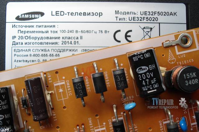
All TV sets are the same in their structure and consist of a power supply unit (PSU), a motherboard and an LCD backlight module (lamps are used) or LED (LEDs are used). It is not worth repairing the motherboard on your own, but the power supply unit and screen backlight lamps are quite possible.
As already mentioned, the design and principle of operation of LED and LCD TVs, regardless of the manufacturer, are the same. Of course, there are some differences, but they do not play a significant role in the diagnosis of faults. Often, in the event of a problem with the power supply, the LCD TV does not turn on at all, while there is no indication, or it turns on for a while and turns off spontaneously. Using an example, the repair of a DAEWOO LCD power supply unit (can be applied to plasma) is considered, which is not much different from repairing an LG TV, as well as Toshiba, Sonya, Rubin, Horizon and similar models.
- First of all, before you repair the TV, you need to remove the back panel of the device with a screwdriver by unscrewing the screws. On some models, the rear wall may be latches installedwhich must be handled with care so as not to break them.
- After removing the cover, you will see the power supply unit, consisting of several modules on the left, and the motherboard on the right.
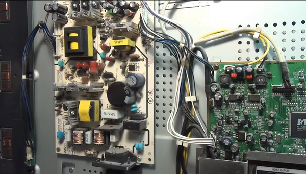
- On the power supply board you can see 3 transformers: the bottom one is the mains rectifier choke, the top one on the left (large) feeds the inverter, and on the right is the standby power supply transformer. You need to start checking with it, since it turns on the standby mode of the TV receiver.
- Duty transformer when the device is connected to the network, it should give out a voltage of 5 V. In order to correctly find the wire on which you need to measure the voltage, you can use the diagram, or you can see the markings on the case. In this case, opposite the required contact is written - 5 V.
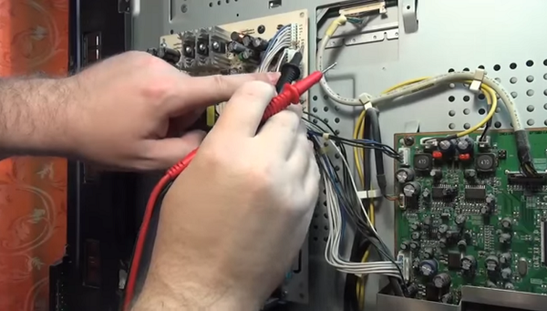
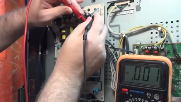
Measurement is taken first open circuitby connecting one probe to the found contact, and the other to the cathode of the diode on the radiator. In this case, there is no break.
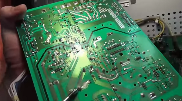

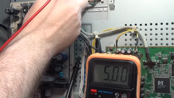

As you can see from the review presented above, repairing TV power supplies with your own hands is not such an overwhelming task. Following this description, you can also repair plasma TVs.
Do-it-yourself TV repair with a kinescope, for example, such as: Rubin, Horizon, Sharp 2002sc, LG TVs, as well as repair of the Vityaz TV, begins with checking the power supply unit for operability (this is done if the unit does not turn on). It is checked using incandescent bulbs for 220 V and a power of 60-100 W. But before that, be sure to disconnect the load, namely the horizontal output stage (SR) - connect a lamp instead. The CP voltage ranges from 110 to 150 V, depending on the size of the tube. Must be found in the secondary circuit SR filter capacitor (its values can be from 47 to 220 microfarads and 160 - 200 V), which stands behind the SR power rectifier.
To simulate the load, you need to connect a lamp in parallel to it. To remove the load, for example, in the popular Sharp 2002sc model, it is necessary to find and unsolder the inductor (located after the capacitor), the fuse and the limiting resistance through which the CP stage receives power.
Now you need to connect the power supply to the power supply unit, and measure the voltage under load. The voltage should be between 110 and 130 V if the CRT has a diagonal of 21 to 25 inches (as in the 2002sc model). With a diagonal of 25-29 inches - 130-150 V, respectively. If the values are too high, then it will be necessary to check the feedback circuit and the power supply circuit (primary).
It should be noted that electrolytes dry out during prolonged operation and lose capacity, which, in turn, affects the stability of the module and contributes to an increase in voltage.
When the voltage is too low it is necessary to test the secondary circuits to exclude leaks and short circuits. After that, the diodes for the protection of the power supply of the SR and the diodes for the power supply of the vertical scan are checked. If you are convinced that the power supply unit is working properly, then you need to disconnect the lamp and solder all the parts back. This check can also come in handy when doing DIY Philips TV repairs.
Another common breakdown of the TV that can be eliminated is the burnout of the backlight lamp. In this case, the TV receiver, after switching on, flashes the indicator several times and does not turn on... This means that after self-diagnosis, the device notices a malfunction, after which the protection is triggered. That is why there is no image on the screen.
For example, a Sharp LSD TV receiver with this malfunction was taken, although in this way it is possible to repair Samsung TVs, Sony Trinitron, Rubin, Horizon, etc.
-
To fix the TV, you need to remove the back cover from the TV. This requires a screwdriver or screwdriver.
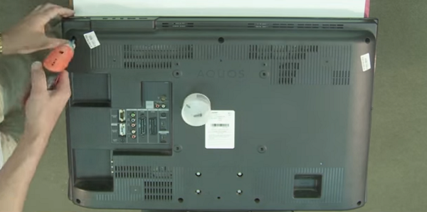

Next, you need to be careful disconnect loops from the matrix.
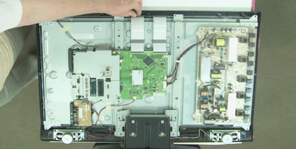
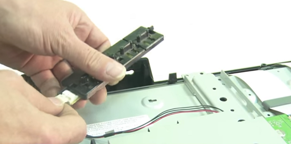

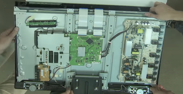

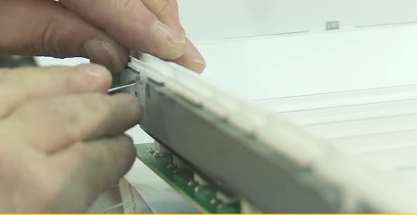

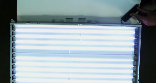

Thus, you can repair the Philips and LG TV with your own hands, and other LCD panels, as well as devices with LED backlight (LED). Owners of the latter type of devices should read the article on repairing LED backlighting, where the whole process is described in detail using the example of an LG TV.
Among the typical and simple reasons that the TV set does not turn on, there may be a remote control or a lack of signal from the antenna cable.
If the TV does not turn on with the remote control, first, you need to make sure the batteries are good. If they are shrunken, replace them.Often the TV set cannot turn on due to contamination of contacts under the buttons. To do this, you can disassemble it yourself, and clean the contacts with a soft cloth from accumulated dirt. If your remote control has been dropped, it is possible damage to the quartz emitter... In this case, it must be replaced. Well, if you filled the remote control with water or some other liquid, and it did not work after disassembling and drying, then it will have to be replaced with a new one.
You can learn more about fixing the remote control in the following video or article.
When repairing TVs LG, Sharp with LCD, Rubin, Horizon with the same screens, a situation often arises when it does not turn on when the device is in good working order. It turns out that the reason may be no TV signal in the antenna cable. This happens due to the operation of the noise suppression protection (in Rubin TVs, they began to install it not so long ago), and the unit goes into standby mode. Therefore, if you find your TV set inoperative, you should not panic, but you need to check the presence of a signal from the transmitting station.
In conclusion, we can say that when you decide to repair a TV set yourself, you should soberly assess your abilities and knowledge in this matter. If you do not feel confident, then it is better to entrust this matter to a telemaster, especially since nobody canceled 220 V, and ignorance of basic safety rules can entail unpleasant consequences.
| Video (click to play). |

