In detail: do-it-yourself akir TV repair is not included from a real master for the site my.housecope.com.
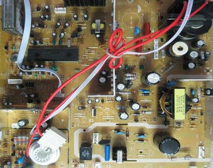
AKIRA CT-2155 chassis 11AK19PROv the device came from another workshop with a faulty power supply. According to the owner, before the breakdown, it sometimes began to turn off. An autopsy revealed a swollen capacity for the line power supply, MC44604P with no signs of life, instead of the Q810 thyristor, 2SA1013 was stuck. After replacing the MC44604P and capacitance, the power supply produced + 10v, but sometimes it started up for a few seconds before the operating voltage. The reason turned out to be in the chip resistor R809 1K, when warming up with a soldering iron, the tin came off one side of the resistor and no longer adhered. After installing a conventional resistor, the power supply began to normally enter the operating mode. Since I did not find a thyristor on sale MCR22-6 installed MCR100-6. After the repair, the power supply gave out 114.8v in the working one, and 13.3v in the duty one.
AKIRA CTV-21MS(he is ARAI CT-2107Dwith minor differences and other position numbers of some parts). Dim screen with changed colors. As if there is not enough brightness signal. Probably there may be other manifestations associated with the video channel. The defect is interesting because everything seems to be normal. A series of repairs due to the wilting of the C 47x50V in the power supply unit and the replacement of a zener diode with 12V 1W, etc. children. the device passed, + 115V is normal and does not bounce into the bowl. dir. A somewhat underestimated voltage from a 12V 1W zener diode (in AKIRA ZD402), only about + 10.5V, brought me into thought. It turned out that the bursting resistor supplying voltage from 3 legs of the TDKS to the power supply rectifier of the zener diode increased its resistance from less than one Ohm to 5 Ohm !! As a result, the rectified voltage dropped below 12V instead of the prescribed 14-16V. This is the second time we meet. Therefore, I recommend that after a standard repair when + 115V is overestimated, check the resistor R443 (in AKIRA) R421 (in AKAI) if its value has increased.
| Video (click to play). |
AKIRA CTV-21M... After eliminating the standard set of faults - with auth. setting skips all stations and, accordingly, there is no sound. Adjusting the circuits, replacing the capacitors in them did not change the situation. I must say that a comrade of the owner of the TV had already tried to repair it before me. After titanic efforts, it turned out that this “craftsman” had replaced the capacitor (hinged from the side of installation from the “-” capacitor C321 to the ground). The native has a nominal value of 4.7n, and he bet 22n. As a result, on the 13th leg of the C68241Y (ident) probe, 5 volts did not appear at any circuit settings! After the replacement, everything was set up like clockwork. And the owner retained its native capacity (it was given away as faulty).
AKIRA 1496small vertical size, about 5 cm. Replacing LA7830 and electrolytes did not work. Open capacitor 1 nF at pin 5 of the frame microcircuit.
AKIRA MK-7... Very similar to FUNAI. Defect when switching on, a squeak is heard. The reason - the output line transistor 2SD1556 burned out due to the increased voltage from the power supply unit (capacitors in the primary circuit dried up). After replacing the electrolytes and the transistor, the TV worked, but there was no color in the SECAM. The cause of this malfunction was the decayed terminals of the color identification coil.
AKIRA CT-2097M(1999). Does not turn on, beeps, + B is understated. With a load - a 60W lamp, the power supply unit outputs 118V - i.e. the norm. NOT - whole. TESTING out. cascade of horizontal scanning lowered + B = + 15V revealed the following. The pulses on the TDKS legs are sometimes normal, sometimes they sit down - at this moment the current consumption along the + V circuit (that is, + 15V) rises to 300mA. If you turn off the OS, it bounces back. When examining the OS, I noticed the conclusions of the KK and SC folded among themselves - they stuck together and began to contact. He pushed the ends apart, again soldered the ends - and the OS is saved. I turn on the TV, a high appears - and then a surprise awaits! The I577 LA7830 is passing away right before our eyes. I had to replace her. the secret proves that it is much easier to find a defect in the lowercase output circuits when the + V supply is too low. Plus, the power elements remain intact.
Akira CT-14HS9there is no general synchronization the suspicion fell on the video processor STV2118 it is good that it was not available became an oscilloscope to watch the power supply at 9v strong ripple dry C300 470.0x35v
AKIRA CTV-21MS... Fault: there are vertical stripes (pillars) on the screen, there is no sound. The capacitor C637 is out of order (112 volt filter after the choke and relay). Ripple penetrated the horizontal scan and secondary power supplies, which is why the power switch of the sound microcircuit did not turn on.
AKIRA CT-14NX9R... Fault: according to the owner, it does not turn on after 1 year of operation. When checking, there is a standby mode, but it is worth turning on, the LED goes out (it seems like it turns on), there is sound, but there is no raster. I checked the power supply. All voltages are normal except for the power supply of the pre-output line scan stage. It is removed from the power supply of the output stage of the horizontal scan through the R629-3.3kOm resistor (5W) and goes through the winding of the swing transformer to the collector of the pre-output transistor. This same resistor periodically went into a break. The dial tone was defined as absolutely serviceable. I put ceramic 3.3 kOm (5W). Just in case, I hooked a radiator for the resistors, as it heats up decently. I did not find a scheme for it. Suitable from ERISSON (chassis 3S10).
Akira CT-21NK9RFault: No sound. R640 breakage with 0.68ohm and, as a consequence, failure of one of the two LA4285s, a frequent defect in those who use headphones.
AKIRA, ERISSON on chassis 3S10 (5800-A3S102-6)Kaliningrad assembly. Fault: two devices in 2 days - vertical stripe. Burnout of the output of the line coil L301 and failure of the parallel R325 1KΩ. New typical defect?
The TV was brought from another workshop with a faulty power supply. Earlier, before a breakdown, sometimes it turned off.
An autopsy revealed a swollen capacity for the line power supply, MC44604P with no signs of life, instead of the Q810 thyristor, 2SA1013 was stuck. After replacing the MC44604P and the capacity, the power supply produced + 10v, but sometimes it started up for a few seconds before the operating voltage. The reason turned out to be in the chip resistor R809 1 kOhm, when heated with a soldering iron, the tin came off one side of the resistor and no longer adhered. After installing a conventional resistor, the power supply began to normally enter the operating mode. Since I did not find a thyristor on sale MCR22-6 installed MCR100-6. After the repair, the power supply gave out 114.8v in the working one, and 13.3v in the duty one.
Dim screen with changed colors. As if there is not enough brightness signal. Probably there may be other manifestations associated with the video channel. The defect is interesting because everything seems to be normal. A series of repairs due to the wilting of the C 47x50V in the power supply unit and the replacement of a zener diode with 12V 1W, etc. children. the device passed, + 115V is normal and does not bounce into the bowl. dir. A somewhat underestimated voltage from a 12V 1W zener diode (in AKIRA ZD402), only about + 10.5V, brought me into thought. It turned out that the bursting resistor supplying voltage from 3 legs of the TDKS to the power supply rectifier of the zener diode increased its resistance from less than one Ohm to 5 Ohm !! As a result, the rectified voltage dropped below 12V instead of the prescribed 14-16V. This is the second time we meet. Therefore, I recommend that after a standard repair when + 115V is overestimated, check the resistor R443 (in AKIRA) R421 (in AKAI) if its value has increased.
After eliminating the standard set of faults - with aut. setting skips all stations and, accordingly, there is no sound. Adjusting the circuits, replacing the capacitors in them did not change the situation. I must say that a comrade of the owner of the TV had already tried to repair it before me. After titanic efforts, it turned out that this "craftsman" had replaced the capacitor (hinged from the side of installation from the "-" capacitor C321 to the ground). The native has a nominal value of 4.7n, and he bet 22n. As a result, on the 13th leg of the C68241Y (ident) probe, 5 volts did not appear at any circuit settings! After the replacement, everything was set up like clockwork. And the owner retained its native capacity (it was given away as faulty).
The vertical dimension is small, about 5 cm. Replacing the LA7830 and electrolytes did not work. Open capacitor 1 nF at pin 5 of the frame microcircuit.
Very similar to FUNAI. Defect when switching on, a squeak is heard.The reason - the output line transistor 2SD1556 burned out due to the increased voltage from the power supply unit (capacitors in the primary circuit dried up). After replacing the electrolytes and the transistor, the TV worked, but there was no color in the SECAM. The cause of this malfunction was the decayed terminals of the color identification coil.
Does not turn on, beeps, + B is understated. With a load - a 60W lamp, the power supply unit outputs 118V - i.e. the norm. NOT - whole. TESTING out. cascade of horizontal scanning lowered + B = + 15V revealed the following. The pulses on the TDKS legs are sometimes normal, sometimes they sit down - at this moment the current consumption along the + V circuit (that is, + 15V) rises to 300mA. If you turn off the OS, it bounces back. When examining the OS, I noticed the conclusions of the QC and SC folded among themselves - they stuck together and began to contact. He pushed the ends apart, again soldered the ends - and the OS is saved. I turn on the TV, a high appears - and then a surprise awaits! The I577 LA7830 is passing away right before our eyes. I had to replace her.
This secret proves that it is much easier to find a defect in the lowercase output circuits when the + V supply is too low. Plus, the power elements remain intact.
There is no general synchronization, the suspicion fell on the STV2118 video processor, it is good that it was not available, the oscilloscope began to watch the power supply at 9v, strong ripple dried C300 470.0x35v.
Fault: there are vertical stripes (pillars) on the screen, there is no sound. The capacitor C637 is out of order (112 volt filter after the choke and relay). Ripple penetrated the horizontal scan and secondary power supplies, which is why the power switch of the sound microcircuit did not turn on.
Fault: according to the owner, it does not turn on after 1 year of operation. When checking, there is a standby mode, but it is worth turning on, the LED goes out (it seems like it turns on), there is sound, but there is no raster. I checked the power supply. All voltages are normal except for the power supply of the pre-output line scan stage. It is removed from the power supply of the output stage of the horizontal scan through the R629-3.3kOm resistor (5W) and goes through the winding of the swing transformer to the collector of the pre-output transistor. This same resistor periodically went into a break. The dial tone was defined as absolutely serviceable. I put ceramic 3.3 kOm (5W). Just in case, I hooked a radiator for the resistors, as it heats up decently. I did not find a scheme for it. Suitable from ERISSON (chassis 3S10).
Fault: No sound. R640 breakage with 0.68ohm and, as a consequence, failure of one of the two LA4285s, a frequent defect in those who use headphones.
Fault: complaints about random switching, switching to AV, floating settings - well-known "glitches" of the processor. Prots - ST92T195D7B1, memory 24С08. The owner is advanced, he was told that the processor is to blame, he "lost" it. After which, as he claimed, the TV worked for an hour and a half without any problems. My actions. At the time of arrival, the TV worked fine. An attempt to provoke a percentage by heating with a soldering iron is unsuccessful. I notice that its 5 V supply is actually about 5.7 V. In the Q004 2SC2703 parametric stabilizer in the base of the transistor, the 5.6 V ZDO56 Zener diode is supplemented with a serially connected ordinary diode for an unknown purpose (this is sometimes done for thermal compensation). Moreover, this is not provided on the board, the installation is hinged, that is, the post-design revision. Here are the extra 0.6-0.7V. This would be understandable if Q004 were composite (Darlington). In general, removing the diode gave 5.06 V at the control point, which corresponds to the inscription on the board + 5V C. The TV was then driven and driven for 2 days, until everything is OK. Approx. This diode is seen in other devices with a similar chassis. Maybe they really planned to use a "compound" in the stabilizer, and then changed their minds? And yet - perhaps processors of this type will lend themselves well to "roasting".
Fault: two devices in 2 days - vertical stripe. Burnout of the output of the line coil L301 and failure of the parallel R325 1KΩ.
Fault: the power supply unit does not start, we change the standard set of STRG6653, an optocoupler (better than PC120), 2SC1815 on an optocoupler, sometimes the R610 resistor by 680 ohms flies out. There were returns with the native optocoupler, there were no problems when installing the PC120. Also, in this model of any diagonal, memory often flies out. Entering the service Press from the remote MENU, then again MENU, Q.VIEW, MUTE.
Good luck with the repair! Visit our Forum.

If you have a UPS (uninterruptible power supply), a TV or monitor starts to turn off spontaneously, interference is visible on the screen, the raster size changes, etc., then in addition to the reasons described in this article, it is often encountered such as the loss of contact in connectors and elements on the board. More details ...

Probably, many are familiar with the situation when the TV stopped showing signs of life when the owner intended to turn it on. Now we are calm about this, since we understand that you can use another TV in the next room or in the kitchen, and the faulty device can be repaired over time. But, if you look back thirty, forty years ago, the refusal of the TV to turn on would be perceived as a big nuisance. TV then, despite the ideology of the programs, for many people was the only window into the world. It was in no way possible to skip the episode “Seventeen Moments of Spring”, and the feelings about this seemed quite reasonable.
There is no doubt that the technique has become more reliable and technologically advanced over time, its weight and dimensions have decreased, and many new user and multimedia functions have been added. However, nowadays, as well as at the dawn of its formation, television receivers are sometimes prone to failures when turned on. There may be many reasons for this, and the apparatus itself is not always the “culprit” of such strange behavior.
It is quite easy to verify the opposite. You need to check the electrical outlet where the cable from the TV is inserted. Plug in a table lamp and make sure it works. Remember where your device has the power button, and if there is one at all. This is no joke, many owners forget about its existence, using only the remote control.
The assortment of TV sets is so diverse and wide that even a master on TV in a model not very well known will take some time to find the mains switch. These elements of the scheme tend to hide in nooks and crannies, below, on the side, behind and be completely invisible. Accidentally hitting this button and not noticing it, then you can ask for a long time the question "Why does the TV not turn on?"
Of course, situations with a button or a bad outlet are not typical and are quite rare, but by checking these things it is worth starting to diagnose the reasons why the “box” does not want to turn on. Most often, the receiver itself is to blame and the owner has to make a decision whether to call a master or fix the TV with his own hands.
For many men who consider themselves technically literate, the issue of TV repair does not seem so difficult. “There you just need to replace the fuse, or something else, but to fix it you need a tester, a soldering iron and a circuit,” some confident people think so. However, the desire to repair the device on its own can decline after the cover is removed from the device and access to the boards and blocks of a modern TV is obtained.
The fuse, as we are used to seeing it, in the receiver, most often, is one and in most cases intact, if there were no farce-majeure circumstances in the form of a thunderstorm or large voltage surges in the electrical network.It may well be that the fuse on one of the boards has blown, but most of the "fuses" are now made in an SMD case and the search for a faulty one may take a long time, since there can be dozens of these components, and they are located in any television unit. It is rather difficult to visually determine their presence in the circuit and distinguish them from similar in appearance capacitors or resistors without proper skill.
Let's say the search was successful. Here it is - a burnt out "fuse" (fuse), which needs to be replaced and the hope that the TV will again delight us with juicy stories and heartfelt stereo sound will come true. However, joy can be premature. Questions should arise: "What is the rating of the defective fuse?" and "Why did it burn out?" If you don't think about these things and just solder a wire instead of a spare part, you can discover a lot of new things: see the smoke from a large microcircuit or hear the crackle of exploding transistors. This means that you have not found the cause of the blown fuse and, as a result, significantly increased the cost of further repairs.
For an experienced TV technician, the socket for the fuse in the power supply hastily wrapped in wire, causes sacred awe, horror in the eyes and the understanding that this device cannot be restored quickly and painlessly, that you cannot earn a lot, and you will have to “sit” with it for a long time, looking for changing what in ordinary life is not in the habit of failing. The most unpleasant thing in this case is the unpredictability and lack of logic when searching for defective parts.
Situation analysis and assessment of the factors affecting the occurrence of a malfunction are an integral part of the professional skills that an experienced TV master... Finding the root cause due to which various components of the television chassis, including fuses, can fail, is the main task of a specialist. It is impossible to repair, hoping to "maybe", without having firm confidence that the defect will not recur in the future.
A simple example. Panasonic CRT TV does not turn on. Measurements show that a 56 volt zener diode is broken in the tuner tuning voltage generation circuit, which performs a purely protective function, and its presence or absence in a properly operating chassis is not at all necessary. Due to inexperience, when repairing with your own hands, replacing this part leads to its repeated burnout. If the zener diode is not installed at all, the TV can turn on and work for a while until the line transistor, frame microcircuit or line transformer burns out. The reason for this behavior is in the overestimated voltage that the power supply gives out, and if even deeper, in the loss of the nominal capacity of two electrolytic capacitors of 47 microfarads. in the primary circuit of this block. This is the root cause of all troubles.
There is much more to be said about why the TV won't turn on. This note focuses on the human factor in such a situation and on the fact that always when repairing a TV, as, indeed, any technically complex device, one should look for the cause and eliminate the consequences caused by it. An attempt to restore the TV's performance on its own may not always end in success. You need to be ready for such a turn and think a hundred times before deciding on this step. It may be worth calling a foreman on TV for repair and, accepting a job, pay, first of all, his experience and knowledge, and not the ability to solder and use a tester and a circuit.
Do not forget to bookmark this page on your social networks!
Repair of the power supply unit of the CRT TV.
See also:
Epic repair of Panasonic-a
Our group for the repair and analysis of equipment - = TechnoNostalgia = -
LIVE CHANNEL
Twitch
Main channel
Donate can be supported by the link:
= Starter Repair Kit: ==
= Multimeter https://ali.pub/3vqoe ==
= Soldering iron https://ali.pub/qt6np ====
= Solder https://ali.pub/uhax5 ======
=== Good luck with radio creation =) ====
Video Simple AKIRA TV repair (not included) PowerStation channel
It is no secret that a breakdown of a television receiver can ruin the mood of any owner. The question arises, where to look for a good master, do you need to take the device to a service center? You need to spend your time on this, and what is important - money. But, before calling the master, if you have basic knowledge of electrical engineering and know how to hold a screwdriver and a soldering iron in your hands, then repairing the TV with your own hands in some cases is still possible.
Modern LCD TVs have become more compact and easier to repair. Of course, there are breakdowns that are difficult to detect without special diagnostic equipment. But most often there are malfunctions that can be detected even visually, for example, swollen capacitors... With such a breakdown, it is enough to evaporate them and replace them with new ones with the same parameters.
All TV sets are the same in their structure and consist of a power supply unit (PSU), a motherboard and an LCD backlight module (lamps are used) or LED (LEDs are used). It is not worth repairing the motherboard on your own, but the power supply unit and screen backlight lamps are quite possible.
As already mentioned, the design and principle of operation of LED and LCD TVs, regardless of the manufacturer, are the same. Of course, there are some differences, but they do not play a significant role in the diagnosis of faults. Often, in the event of a problem with the power supply, the LCD TV does not turn on at all, while there is no indication, or it turns on for a while and turns off spontaneously. Using an example, the repair of a DAEWOO LCD power supply unit (can be applied to plasma) is considered, which is not much different from repairing an LG TV, as well as Toshiba, Sonya, Rubin, Horizon and similar models.
- First of all, before you repair the TV, you need to remove the back panel of the device with a screwdriver by unscrewing the screws. On some models, the rear wall may be latches installedwhich must be handled with care so as not to break them.
- After removing the cover, you will see the power supply unit, consisting of several modules on the left, and the motherboard on the right.
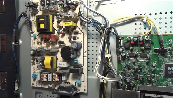
- On the power supply board you can see 3 transformers: the bottom one is the mains rectifier choke, the top one on the left (large) feeds the inverter, and on the right is the standby power supply transformer. You need to start checking with it, since it turns on the standby mode of the TV receiver.
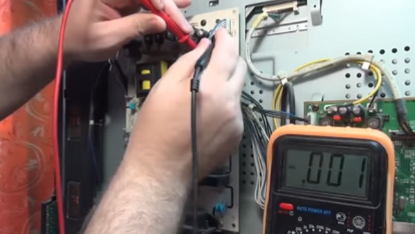
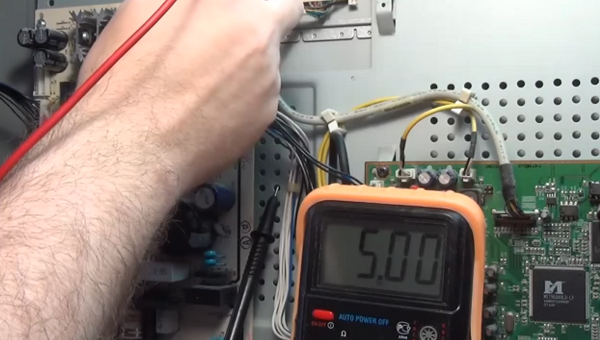
- Duty transformer when the device is connected to the network, it should give out a voltage of 5 V. In order to correctly find the wire on which you need to measure the voltage, you can use the diagram, or you can see the markings on the case. In this case, opposite the desired contact is written - 5 V.
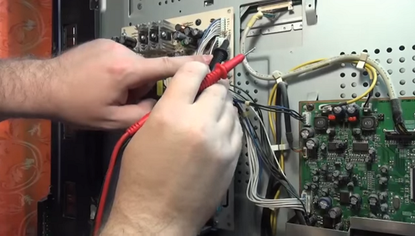
Measurement is taken first open circuitby connecting one probe to the found contact, and the other to the cathode of the diode on the radiator. In this case, there is no break.
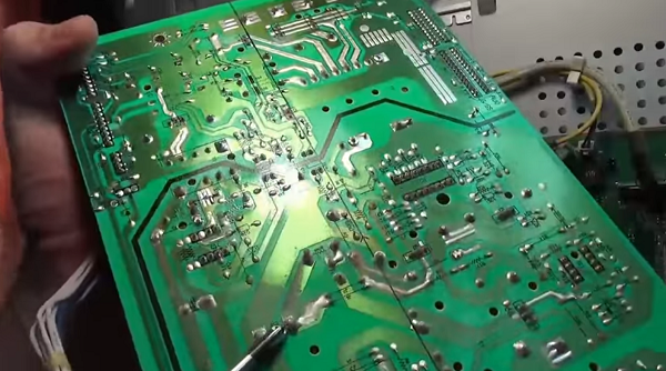


As you can see from the review presented above, repairing TV power supplies with your own hands is not such an overwhelming task. Following this description, you can also repair plasma TVs.
Do-it-yourself TV repair with a kinescope, for example, such as: Rubin, Horizon, Sharp 2002sc, LG TVs, as well as repair of the Vityaz TV, begins with checking the power supply unit for operability (this is done if the unit does not turn on). It is checked using incandescent bulbs for 220 V and a power of 60-100 W. But before that, be sure to disconnect the load, namely the horizontal output stage (SR) - connect a lamp instead. The CP voltage ranges from 110 to 150 V, depending on the size of the tube. Must be found in the secondary circuit SR filter capacitor (its values can be from 47 to 220 microfarads and 160 - 200 V), which stands behind the SR power rectifier.
To simulate the load, you need to connect a lamp in parallel to it. To remove the load, for example, in the popular Sharp 2002sc model, it is necessary to find and unsolder the inductor (located after the capacitor), the fuse and the limiting resistance through which the CP stage receives power.
Now you need to connect the power supply to the power supply unit, and measure the voltage under load. The voltage should be between 110 and 130 V if the CRT has a diagonal of 21 to 25 inches (as in the 2002sc model). With a diagonal of 25-29 inches - 130-150 V, respectively. If the values are too high, then it will be necessary to check the feedback circuit and the power supply circuit (primary).
It should be noted that electrolytes dry out and lose capacity during prolonged operation, which, in turn, affects the stability of the module and contributes to an increase in voltage.
When the voltage is too low it is necessary to test the secondary circuits to exclude leaks and short circuits. After that, the diodes for the protection of the power supply of the SR and the diodes for the power supply of the vertical scan are checked. If you are convinced that the power supply unit is working properly, then you need to disconnect the lamp and solder all the parts back. This check can also come in handy when doing DIY Philips TV repairs.
Another common breakdown of the TV that can be eliminated is the burnout of the backlight lamp. In this case, the TV receiver, after switching on, flashes the indicator several times and does not turn on... This means that after self-diagnosis, the device notices a malfunction, after which the protection is triggered. That is why there is no image on the screen.
For example, a Sharp LSD TV receiver with this malfunction was taken, although in this way it is possible to repair Samsung TVs, Sony Trinitron, Rubin, Horizon, etc.
-
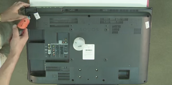
To fix the TV, you need to remove the back panel from the TV. This requires a screwdriver or screwdriver.

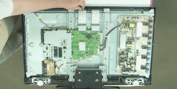
Next, you need to be careful disconnect loops from the matrix.
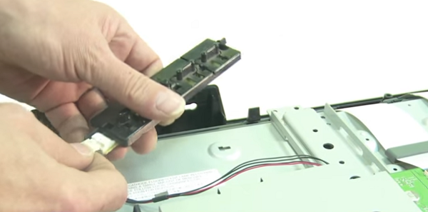

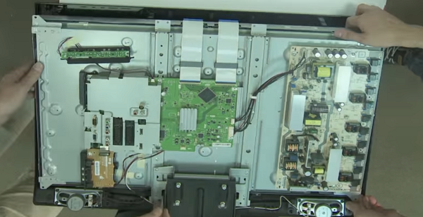

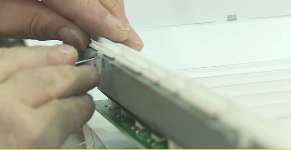

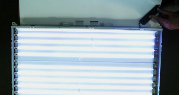

Thus, you can repair the Philips and LG TV with your own hands, and other LCD panels, as well as devices with LED backlight (LED). Owners of the latter type of devices should read the article on repairing LED backlighting, where the whole process is described in detail using the example of an LG TV.
Among the typical and simple reasons that the TV set does not turn on, there may be a remote control or a lack of signal from the antenna cable.
If the TV does not turn on with the remote control, first, you need to make sure the batteries are good. If they are shrunken, replace them. Often the TV set cannot turn on due to contamination of contacts under the buttons. To do this, you can disassemble it yourself, and clean the contacts with a soft cloth from accumulated dirt. If your remote control has been dropped, it is possible damage to the quartz emitter... In this case, it must be replaced. Well, if you filled the remote control with water or some other liquid, and it did not work after disassembling and drying, then it will have to be replaced with a new one.
You can learn more about fixing the remote control in the following video or article.
When repairing TVs LG, Sharp with LCD, Rubin, Horizon with the same screens, a situation often arises when it does not turn on when the device is in good working order. It turns out that the reason may be no TV signal in the antenna cable. This happens due to the operation of the noise suppression protection (in Rubin TVs, they began to install it not so long ago), and the unit goes into standby mode. Therefore, if you find your TV set in an inoperative state, you should not panic, but you need to check the presence of a signal from the transmitting station.
In conclusion, we can say that when you decide to repair a TV set yourself, you should soberly assess your abilities and knowledge in this matter. If you do not feel confident, then it is better to entrust this matter to a telemaster, especially since nobody canceled 220 V, and ignorance of basic safety rules can entail unpleasant consequences.
Do-it-yourself TV repair is a responsible business, since today a large number of different models (LCD, LSD, CRT) are presented on the market, each of which has its own technological features. Therefore, the approach to each type of TV is individual; in some cases, special skills will be required (knowledge of electronics, experience with a soldering station).
Before proceeding with the repair of television equipment, it is necessary to find out the cause of the problem.
The most common problems are:
- TV screen does not turn on - this can happen with an old picture tube screen and with the most modern television panel. Basically, this symptom is characteristic of a blown fuse. When repairing, it should be borne in mind that the appropriate fuse must be selected for each model. And also experts recommend paying attention to the diode bridge, power supply, wire, perhaps the cause of the malfunction lies in these elements. Read also what to do if Samsung TV does not turn on.
- Faint, barely noticeable picture - this kind of breakdown happens with LCD / LCD monitors. The most likely cause of the malfunction: faulty diodes, device backlighting.
- There is no sound, the screen "wheezes" - most likely, the sound amplifier or microcircuit is out of order. Also read what to do if there is sound, but there is no picture.
- Monitor is on, no picture - Perhaps the cause of the problem is in the video processor or in the receiving unit.
You should be aware that if a darkening of the board or rupture of elements is detected during a visual inspection of television equipment, then it is not recommended to immediately start replacing parts. Since such factors indicate a short circuit that could have occurred in another section of the TV. Therefore, if you do not eliminate the cause of the short circuit, but simply change the failed elements, then the situation will repeat itself.
To repair television equipment, the following tools and equipment may be required:
- Screwdriver Set;
- hex keys (in rare cases);
- pliers;
- soldering station (for repairing modern monitors);
- screen layout (can be downloaded on the Internet);
- multimeter;
- oscilloscope.
Many LCD screen problems can be dealt with on your own. But you should know that these screens require more careful handling than, for example, CRT TVs.
First of all, the user needs to study the instructions for his model, and only after that start repairing the LCD or LED screen. You should know that LCD TVs use fluorescent bulbs for backlighting, while LEDs use LEDs.
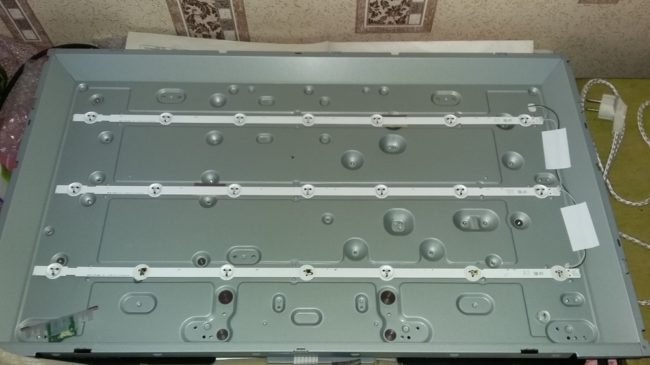
The TV may not function due to lack of power, to check this, you need to do the following:
- Open the back cover of the LCD TV with tools.
- Disconnect the wires that are connected to the device matrix.
- Connect a working light bulb to the contacts.
- Some panels have more than one light source, in which case they must be tested as well. This can be done as follows: pull out the TV matrix and connect it to the network, it will immediately become clear which lamp is out of order.
After the faulty luminaire is found, it must be replaced. This procedure should be carried out as carefully as possible. In most cases, the lamp can be taken out even without removing the matrix - you need to move the protection elements aside and take out the burned-out part using a soldering station. Then a new lamp is installed in the same way.An important rule is that the new lamp must be completely identical to the old one.
Another common problem with these models is damage to the monitor. But in this case, it is not advisable to repair LCD TVs, since it is easier to buy a new screen. This test scheme can also be used to repair plasma televisions of all types. Read also how to fix the LED backlight yourself.
Each manufacturer has its own weak points, so below is a selection of the most common LCD screen breakdowns.
Often, users of this brand are faced with such a problem that when turned on, the device beeps without interruption. This symptom usually indicates that a leak has occurred. It is recommended to try replacing the preout stage diode.
Another common problem is that the monitor turns on and off itself. The main reason for this breakdown is a failed transistor, it is necessary to replace it. It is recommended that such malfunctions be eliminated on their own only by people who have experience in repairing television equipment.
DIY Philips TV repair is recommended if the problem is minor: settings are lost, cable replacement is required.
If the breakdown is complex, then it is better to entrust its elimination to specialists who will not only professionally perform repairs, but also issue a guarantee.Therefore, if the repaired screen stops working again, the user may demand a refund.
LG flat screen owners may have a problem saving settings. Such a problem does not require contacting the masters, you can repair the LG TV yourself. It is enough to switch the device to another operating mode, and all settings will be saved.
As well as in the case of other LCD models, if the problem is serious, then it is not recommended to repair an LG TV with your own hands, it is better to contact a specialist.
Despite the fact that today most consumers prefer the most modern plasmas, CRT screens are still in demand. These TVs have their advantages: they are inexpensive, easy to operate, and the quality of the transmitted picture is still high.
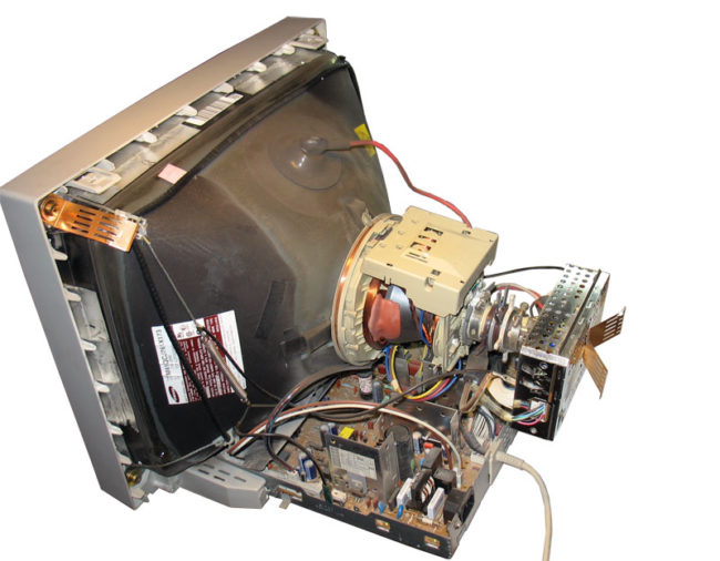
The main problems with CRT devices:
- the CRT TV does not turn on - just like on devices of a different type, first of all, you need to check the integrity of the fuses;
- a diode bridge malfunction is a common problem with CRT receivers, you can fix the TV only after making a "ringing", you will need a multimeter from the equipment;
- breakdown of the posistor is considered the most serious problem; in order to check, it is necessary to turn off the TV's power circuit, then start it again. After, observe the lamp, if it goes out, it means that the posistor is out of order. First of all, you need to adjust the resistance of the network, and then replace the part;
- burnout of a transistor or capacitor - such a malfunction can be easily replaced by visual inspection (on black carbon parts), repair is carried out by replacing the part.
Below is a list of problems encountered by owners of CRT TVs.
- The Rubin TV buzzes loudly when connected - most likely, the photodetector needs to be replaced.
- Ruby does not turn on, the indicator is off - voltage surges in the transistor.
- The Horizon TV does not have a blue tint, as well as the white balance is disturbed - this is mainly due to a break in the resistor.
- There is sound, no image - the cause of the problem lies in poor contact of the power connector of the screen board. It is recommended to use a soldering iron to solder the harness into the Horizon TV board.
- The screen does not turn on - there is a problem with the power supply.
- A horizontal strip appears on the monitor - repairing a Vityaz TV consists in fixing a problem in the frame scan microcircuit.
Since the malfunction of the power supply is one of the most common problems of all types of TVs, it is necessary to study it in more detail.
Since all models of LCD monitors do not have fundamentally different design differences, therefore, the diagram below can be applied to all TVs (Toshiba, Horizon, Samsung, Sony, Rubin).
Repair of monitors equipped with a picture tube, for example, such as (ruby, sharp 2002sc, sony trinitron, vvk), as well as repair of Samsung TV, Panasonic. always starts checking the power supply.
Testing is carried out using an incandescent lamp, but before performing the procedure, it is necessary to disconnect Sharp c2002sc, Samsung or another screen from the load (horizontal cascade). The horizontal scan voltage can vary from 110 to 150 V, it depends on the size of the picture tube. It is required to find a sweep filter capacitor in the TV circuit. Next, you will need to connect a light bulb, in order to remove the load, it is necessary to unsolder the choke and the fuse through which the JV element consumes power. This scheme is used for sharp screens since 2002sc.
| Video (click to play). |
After that, connect the power adapter to electricity and measure the voltage, if the values exceed the norm, you will have to check the feedback circuit of the power supply.If the power supply unit is in good condition, then the light bulb is removed and all the elements are soldered into place. This is the basic information on how to repair a TV with your own hands.

