In detail: do-it-yourself polar TV repair from a real master for the site my.housecope.com.
POLAR 5401 3701 in the absence of reception, do not rush to change the tuner, the memory often flies, in the service check the IF frequency should be 38.9 and flies to some strange 58 ?! ... service - shortly close contacts 1 and 3 on the X-702 connector, RUBIN M06 is also susceptible to this sore. To memorize the settings, press kn (TV) on any RC-5 remote control.
POLAR 5400/01 with a CTV64 / P01 processor came for repair after the owner accidentally entered SERV mode. The UHF range does not work, the menu items are not selected from the remote control, but the geometry remained intact in the native firmware. After rewriting the memory from a similar device on the programmer, the TV worked fine, only the individual settings of the raster geometry did not match. There is no documentation for this POLAR model yet. Therefore, I had to find two lines in the old firmware, which contained information: vertical size, linearity, centering. After transferring these data to the new firmware, the geometry fell into place, all the functions of the device were restored.
POLAR51001 / 01... The power supply unit assembled on the TDA-4601 is faulty. Burnt out VT801 BU508DF. If you hurry and do not find the reason, you can burn BU508DF again, since R811 270K was cut off.
Polar of all models on certain channels - when the picture changes from a white background to a dark one, the sound disappears. It is treated by replacing the R111 470om resistor with 1kom.
Polar 37CTV 2010 made in Russia, does not turn on in standby mode, the line power supply is normal when it is turned on in the operating mode, it immediately enters protection. It is worth TDKS of unknown origin (similar to China), we immediately change it and everything is OK. That's what the emblem means BUY RUSSIAN and we have enough work!
| Video (click to play). |
TV POLAR-5100 / 0.1.5400 / 0.1 does not turn on from the duty room, but can turn on in the evening or every other day. Someone had a hand in repairs, but to no avail. Email the schema is, of course, missing. It turned out that the VT802 transistor (KT961G) is buggy (it looks like a key controlled by a processor). When leaving the duty room on the emitter, it has about 8.9v., And should be 11v. After replacement, everything is OK.
POLAR 5400/01 the power supply is out of order. R811 270 kOhm cut off, TDA4601D, BU508A, R814 47. After replacing faulty parts, the power supply unit normally worked to load the el. lamp 60 W. But with a normal switch on, the power supply clicks at a frequency of 1 Hz, the TV cannot go into either standby or operating mode. The reason was the underloading of the power supply unit, in standby mode. After setting the resistance of 15 kOhm 2 W from the line supply to the ground, the power supply unit turns on normally and keeps the standby mode.
Polar 54CTV2039... No reception on all bands. In places where there should be a station on the screen, a grid or stripes without any hints of synchronization - the reason is a leak in the C101 tank (circuit of the autotuning filter circuit of the reference loop m / s TDA8842 (pin 5))
POLAR 5401 does not tune to channels. Defect: breakage of the quenching resistor R820 18kOhm 1W, in the formation of the tuning voltage + 33V.
1.) 70CTV3052 and 63CTV3052 Recommendations for eliminating the excitation of the subwoofer in TV standby mode.
2.) 70CTV3055 Recommendations for eliminating the ghosting effect.
3.) Recommendation for preventing the failure of the TDA8943 microcircuit in TVs of models 54CTV4029 and 54CTV1229 with a picture tube 54SX538Y22
4.) Interchangeability of TDA9302H and STV9302A vertical scan microcircuits.
5.) Replacing the TDA9381 processor version POLAR1.0 with the TDA9381 processor version POLAR1.1.
6.) Interchangeability of tuners used in the production of POLAR TVs, depending on the type of processor and printed circuit board used.
Polar 63CTV3055 does not tune to programs. When tuning in the station area, a visible change in noise, but the image does not appear. The voltage at pin 47 of TB1240 changed from 3.5v to 5.2v, it was propped up with IC261 HFE4052B, the video switch.
Polar 70CTV3055 the TCL-A18V01-TO 87CP38N-4GD1 processor turned on the TV, sometimes produced very strange inscriptions and did not want to control the TV. After installing a new one, everything worked fine. But after two days of running, the image on AV and TV periodically began to disappear. The reason turned out to be IC261 HFE4052B, video signal switcher.
Polar 54CV4029 There is no general synchronization. The reason turned out to be in C135 0.1 microfarad. The capacitor leaked about 30 kΩ. The voltage at pin 42 of the TDA9381PS from normal has changed by 0.7 volts.
POLAR 5101 Narrow band (frame TDA9302H), no + 13V on the frame. Replacing the VD106 diode (intermittent break)
POLAR 54CTV4029 a frequent cause of malfunction when the UC3842 breaks to shreds and the power supply fails is the loss of the capacitance of the input capacitor C804 150mk / 400v.
POLAR 54CTV2039 Fault: channels are not switched, the volume is not adjusted, the TV does not turn off from the remote control to standby mode. Reflash the 24C08 memory chip on the programmer.
POLAR 54CTV4535 monoblock DVD. Fault: not incl. DVD, the disc remains in the tray. When checking the service mode, there was a failure in line AV2. There was a value of 0, but you need 5. Entering the service mode: Turn on the TV in operating mode, then switch to standby mode, press the (STATUS), (MENU), (MUTE), (TIMER) keys on a regular remote control. The service menu will appear on the screen.
Polar 70TV3055... When a Polivision 042 digital video recorder is connected to video input # 2, a certain potential appeared on the DVR body, probably through the “ground” contact of the “SVEN” surge protector, which was included in the two-wire electrical network. The V / recorder itself was turned off by a button on the case, and the adapter plug was included in the filter (probably the “ground” (220 V) adapter wire was connected to the “case” (12 V). As a result, when connecting the low-frequency cord to the V / recorder, I received an electric shock and the image on the TV disappeared at LF input No. 1 and HF, a weak, distorted signal passed through LF input No. 2. The IC962 PHILIPS HEF4052BP microcircuit failed. There is no such thing in the city of Stavropol, but a CD4052B was found. ...
POLAR 54/01 chassis S-0602 Fault: the screen darkens and flickers. 13 volts missing on VD406. It is required to replace the diode, ring as good.
POLAR 5401 chassis S-0602 Fault: synchronization is lost. Check and, if necessary, replace C107, TDA8842.
POLAR 70CTV3055... Fault: after turning on the TV, (sometimes immediately or after 10-15 minutes) the programs themselves began to switch, the programs were tuned and the volume increased. Changing the firmware didn't help. I thought the PROCESSOR - but. The whole problem turned out to be in the - BUTTON on the front panel (TV / AV). It is on a metal base. And the leak on this base was causing this glitch. He cured - by replacing, and so that there was no repetition, he replaced them all.
POLAR 5101 chassis S-0401... Fault: does not turn on. The power supply unit is in a deplorable state: IC801 UC3842AN, C812 470pFx1600v exploded, R810, R812 charred, R801, R813, R814 in the cliff, and naturally VT801 IRFIBC40G is faulty. The culprit of the tragedy was most likely the C812 470pFx1600v.
Polar 5101 Chassis S-0401... Fault: HR TDA9302H burned out. After replacing it, the TV worked, but when the board was installed in the case along the guides, the staff burned out again. It turned out that the resistor R905 in the power supply unit was poorly sealed, and when mechanically applied to the board, the power supply unit produced overestimated voltages.
Polar 51CTV1029 Fault: there is a raster, no OSD, a blurry blue-green glow on the screen, and the raster is full. Weak reaction to focusing, with an increase in the accelerating one, a rustle is heard from under the deflecting deflector, a sensation of turn-to-turn breakdown. Ring cracks on the personnel microcircuit. The frame scan is made according to the scheme with a bipolar power supply. After soldering the microcircuit, all O.K.
POLAR 54CTV3060 Chassis М23 Composition: percent TCL-A19V01-TO, 24CO8, LA7840, (2S) K2996, MC44608, TDA7057QA, TC4066BP. The TV was repaired after a thunderstorm. Fault: no switching on. After replacing burnt-out parts: IC 801, Q801 K2996, IC802 TLP621, Q831 C1815, Q832 C1815, Q211 BEC144, TCL-A19V01-TO processor with TCL-A30V02-TO analog, it is also possible to replace with TMPA8821, TCL-A19V03-TO. The TV turned on, but the raster filled a bright green color and the lines of the return path of the beam, there is sound, the channels are switched, if the accelerating voltage is removed, a low-contrast image is visible. When disconnected on the connector P201- (G) - gave an excellent result - the image went, but without the green! Supply voltages are normal: 112V, 18V, 9V, 8V, 5V.The first thing that came to mind was the firmware! It flew off during a thunderstorm, but replacing it with a clean IC001 24CO8 memory did not work! The screen is the same! Entering the factory service settings did not solve the problem either, everything is okay there!
1. Entering the service mode: Turn on the TV in operating mode. Using the “VOL -” key from the TV control panel, set the volume level to the “00” position and while holding it, press the “Display” key on the remote control. The service menu will appear on the screen. D 2. The selection of the service menu page is carried out with the remote control using the numeric keys “1-0”. 3. Parameter selection - using the “PRO” keys. 4. Changing the value of the parameter with the “VOL. The exit from the service mode with saving the settings is carried out by transferring the TV to the “STANDBY MODE”. Analysis of the circuit and verification of the piping allowed us to decide on the marriage of the TCL-A30V02-TO processor at 51 G OUT voltage 0V, although there is no short circuit when checking for Ohms. Replacement of marriage - TCL-A30V02-TO, the TV has been restored!
Polar 5101... B / p on TDA4601D. Fault: BU508A punctured in the power supply. After replacing it, the b / p gave an underestimated power supply, as in an overload. After disabling the CP, BU508A immediately struck again in the power supply unit. The reason is the dangling R811 (270k).
POLAR CTV-2029 Fault: the TV is working, there is an OSD, there is a teletext. There is no reception from the air. I checked the signal flow from the channel selector to the video processor with an oscilloscope, there is a signal. I checked the switching of AV-TV signals, it gave nothing. Re-flashing the 24С08 memory and the TV began to work. The TV was on standby all the time, they did not disconnect from the network.
Perhaps this article will help you cure your sick TV friend
Fault 1. POLAR 5400/01 with a CTV64 / P01 processor came for repair after the owner accidentally entered the SERV mode. The UHF range does not work, the menu items are not selected from the remote control, but the geometry remained intact in the native firmware. After rewriting the memory from a similar device on the programmer, the TV worked fine, only the individual settings of the raster geometry did not match. There is no documentation for this POLAR model yet. Therefore, I had to find two lines in the old firmware, which contained information: vertical size, linearity, centering. After transferring these data to the new firmware, the geometry fell into place, all the functions of the device were restored.
Fault 2. POLAR51001 / 01. The power supply unit assembled on the TDA-4601 is faulty. Burnt out VT801 BU508DF. If you hurry and do not find the reason, you can burn BU508DF again, since R811 270K was cut off.
Fault 4.POLAR 5401 3701 in the absence of reception, do not rush to change the tuner, the memory often flies, in the service check the IF frequency should be 38.9 and flies to some strange 58 ?! ... service - short-term contacts 1 and 3 on the X-702 connector, RUBIN M06 is also susceptible to this sore. To memorize the setting, press kn (TV) on any RC-5 remote control.
Fault 5. Polar 37CTV 2010 is made in Russia, it does not turn on in standby mode, the line power is normal when it is turned on, it immediately enters protection. It is worth TDKS of unknown origin (similar to China), we immediately change it and everything is OK. That's what the emblem means BUY RUSSIAN and we have enough work!
Fault 6. Polar 54CTV2039. No reception on all bands. In places where there should be a station on the screen, a grid or stripes without any hints of synchronization - the reason is a leak in the C101 tank (circuit of the autotuning filter circuit of the reference loop m / s TDA8842 (pin 5))
Fault 7. POLAR 5401 does not tune to channels. Defect: breakage of the quenching resistor R820 18kOhm 1W, in the formation of the tuning voltage + 33V.
Fault 8.TV POLAR-5100 / 0,1,5400 / 0,1 does not turn on from duty, but can turn on in the evening or every other day. Someone had a hand in repairs, but to no avail. Email the schema is, of course, missing. It turned out that the transistor VT802 (KT961G) breaks through (it looks like a key controlled by a processor). When leaving the duty room on the emitter, it has about 8.9v., And should be 11v. After replacement, everything is OK. 7.) The POLAR 5400/01 power supply unit is out of order.R811 270 kOhm cut off, TDA4601D, BU508A, R814 47. After replacing faulty parts, the power supply unit normally worked to load the el. lamp 60 W. But with a normal switch on, the power supply clicks at a frequency of 1 Hz, the TV cannot go into either standby or operating mode. The reason was the underloading of the power supply unit, in standby mode. After setting the resistance of 15 kOhm 2 W from the line supply to the ground, the power supply unit turns on normally and keeps the standby mode. 10.) POLAR
Fault 9. 70CTV3052 and 63CTV3052 Recommendations for eliminating the excitation of the subwoofer in standby TV mode.
Fault 10. 70CTV3055 Recommendations for eliminating the ghosting effect.
Fault 11. Recommendation for preventing the failure of the TDA8943 microcircuit in 54CTV4029 and 54CTV1229 TVs with a 54SX538Y22 CRT
Fault 12. Interchangeability of TDA9302H and STV9302A vertical scan microcircuits.
Fault 13. Replacement of the TDA9381 processor version POLAR1.0 with the TDA9381 processor version POLAR1.1.
Fault 14. Interchangeability of tuners used in the production of POLAR TVs, depending on the type of processor and printed circuit board used.
Fault 15. Polar 70CTV3055 processor TCL-A18V01-TO 87CP38N-4GD1 turned on the TV, sometimes produced very strange inscriptions and did not want to control the TV. After installing a new one, everything worked fine. But after two days of running, the image on AV and TV periodically began to disappear. The reason turned out to be IC261 HFE4052B, video signal switcher.
Fault 16. Polar 54CV4029 No shared sync. The reason turned out to be in C135 0.1 microfarad. The capacitor leaked about 30 kΩ. The voltage at pin 42 of the TDA9381PS from normal has changed by 0.7 volts.
Fault 17. POLAR 70CTV3055. Fault: after turning on the TV, (sometimes immediately or after 10-15 minutes) the programs themselves began to switch, the programs were tuned and the volume increased. Changing the firmware didn't help. I thought the PROCESSOR - but ... The whole problem turned out to be in the - BUTTON on the front panel (TV / AV). It is on a metal base. And the leak on this base was causing this glitch. He cured - by replacing, and so that there was no repetition, he replaced them all.
Fault 18. Polar 63CTV3055 cannot be tuned to programs. When tuning in the station area, a visible change in noise, but the image does not appear. The voltage at pin 47 of TB1240 changed from 3.5v to 5.2v, it was propped up with IC261 HFE4052B, the video switch. 22.) POLAR 5101 chassis S-0401. Fault: does not turn on. The power supply unit is in a deplorable state: IC801 UC3842AN, C812 470pFx1600v exploded, R810, R812 charred, R801, R813, R814 in the cliff, and naturally VT801 IRFIBC40G is faulty. The culprit of the tragedy was most likely the C812 470pFx1600v.
Fault 19. Polar 5101 Chassis S-0401. Fault: HR TDA9302H burned out. After replacing it, the TV worked, but when the board was installed in the case along the guides, the staff burned out again. It turned out that the resistor R905 in the power supply unit was poorly sealed, and when mechanically applied to the board, the power supply unit produced overestimated voltages.
Fault 20. Polar 51CTV1029 Fault: there is a raster, no OSD, a blurry blue-green glow on the screen, and the raster is full. Weak reaction to focusing, with an increase in the accelerating one, a rustle is heard from under the deflecting deflector, a sensation of turn-to-turn breakdown. Ring cracks on the personnel microcircuit. The frame scan is made according to the scheme with a bipolar power supply. After soldering the microcircuit, all O.K.
Fault 21. Polar 5101. B / p on TDA4601D. Fault: BU508A punctured in the power supply. After replacing it, the b / p gave an underestimated power supply, as in an overload. After disabling the CP, BU508A immediately struck again in the power supply unit. The reason is the dangling R811 (270k).
Fault 22. POLAR CTV-2029 Fault: the TV is working, there is an OSD, there is a teletext. There is no reception from the air. I checked the signal flow from the channel selector to the video processor with an oscilloscope, there is a signal. I checked the switching of AV-TV signals, it gave nothing. Re-flashing the 24С08 memory and the TV began to work. The TV was on standby all the time, they did not disconnect from the network.
Fault 23. POLAR 54CTV3060 Chassis М23 Composition: percent TCL-A19V01-TO, 24CO8, LA7840, (2S) K2996, MC44608, TDA7057QA, TC4066BP. The TV was repaired after a thunderstorm. Fault: no switching on. After replacing burnt-out parts: IC 801 MC44608, Q801 K2996, IC802 TLP621, Q831 C1815, Q832 C1815, Q211 BEC144, TCL-A19V01-TO processor with TCL-A30V02-TO analog, it is also possible to replace with TMPA8821, TCL-A19V03-TOThe TV turned on, but the raster filled a bright green color and the lines of the return path of the beam, there is sound, the channels are switched, if the accelerating voltage is removed, a low-contrast image is visible. When disconnected on the connector P201- (G) - gave an excellent result - the image went, but without the green! Supply voltages are normal: 112V, 18V, 9V, 8V, 5V. The first thing that came to mind was the firmware! It flew off during a thunderstorm, but replacing it with a clean IC001 24CO8 memory did not work! The screen is the same! Entering the factory service settings did not solve the problem either, everything is fine there!
Fault 24. Entering the service mode: Turn on the TV in operating mode. Using the "VOL -" key from the TV control panel, set the volume level to the "00" position and while holding it, press the "Display" key on the remote control. The service menu will appear on the screen. D 2. The selection of the page of the service menu is carried out with the remote control using the numeric keys "1-0". 3. Parameter selection - using the "PRO" keys. 4. Changing the value of the parameter - keys "VOL. The exit from the service mode while saving the settings is carried out by transferring the TV to the "STANDBY MODE". Analysis of the circuit and verification of the piping allowed us to decide on the marriage of the TCL-A30V02-TO processor at 51 G OUT voltage 0V, although there is no short circuit when checking for Ohms. Replacement of marriage - TCL-A30V02-TO, the TV has been restored!
Fault 25. Polar 54CTV1029. Fault: no OSD graphics. During the repair process, a faulty VD302 diode was found in the open circuit.
Fault 26. Polar 37CTV4010, Fault: there is no raster, there is sound, with an increase in the accelerating beam, an illumination with a reverse beam appears, the vertical scan microcircuit is working. All three cannons are locked. I found one faulty transistor immediately, it stands at the input from the microcircuit - F422, the base leak is the emitter, about 800 ohms. After replacing the same thing, I ran through the rest of the transistors, everything seems to be normal. Started digging further around the processor, replaced the processor, same thing. Lost the day! I returned to the CRT board, this time I checked the voltage ratio at the base - emitter, on all transistors. I noticed a difference from the others on the blue gun, on this pair the voltage was slightly more than on the red and green guns, I dropped this pair, which are connected in parallel to F422 and F423, and on the last one there was a leak of somewhere in 70 kOhm, the collector is an emitter. It was tested the first time with VK7-9 on Omaha. After replacing it, everything is normal.
Fault 27. POLAR 5101 Narrow band (TDA9302H frame), no + 13V on the frame. Replacing the VD106 diode (intermittent break)
Fault 28. POLAR 54CTV4029 A common cause of malfunction when it breaks the UC3842 to shreds and the power supply fails is the loss of capacitance of the input capacitor C804 150mk / 400v.
Fault 29. POLAR 54CTV2039 Fault: channels are not switched, the volume is not adjusted, the TV does not turn off from the remote control to standby mode. Reflash
memory chip 24С08 on the programmer.
Fault 30. POLAR 54CTV4535 monoblock DVD. Fault: not incl. DVD, the disc remains in the tray. When checking the service mode, there was a failure in line AV2. There was a value of 0, but you need 5. Entering the service mode: Turn on the TV in operating mode, then switch to standby mode, press the (STATUS), (MENU), (MUTE), (TIMER) keys on a regular remote control. The service menu will appear on the screen.
Fault 31.Polar 70TV3055. When a Polivision 042 digital video recorder is connected to video input # 2, a certain potential appeared on the DVR body, probably through the “ground” contact of the “SVEN” network filter, which was included in the two-wire electrical network. The I / recorder itself was turned off by a button on the case, and the adapter plug was included in the filter (probably the “ground” (220 V) adapter wire was connected to the “case” (12V). As a result, when the low-frequency cord was connected to the I / received an electric shock and the image on the TV disappeared at LF input No. 1 and HF, a weak, distorted signal passed through LF input No. 2. The IC962 PHILIPS HEF4052BP microcircuit failed. There is no such thing in the city of Stavropol, but a CD4052B was found. ...
Fault 32. POLAR 54/01 chassis S-0602 Fault: the screen darkens and flickers. 13 volts missing on VD406. It is required to replace the diode, ring as good.
Fault 33. POLAR 5401 chassis S-0602 Fault: synchronization is lost. Check and, if necessary, replace C107, TDA8842.
11/16/2015 Service Center Prosto Service on Yamasheva (tigarbo) 1289
TVs Polar 37CTV3165
Today we're going to troubleshoot a typical Polar 37CVT3165 TV malfunction.
First of all, we put the TV on the table and turn it over with the back wall towards us.
We unscrew the four bolts along the perimeter.
We begin to remove the trains one by one as shown in the picture.
We take out the board.
First of all, we look to see if the fuse indicated in the picture below is working.
Next, we measure the readings of the capacitor indicated in the photo, its values should be about 310-320V.
Next, we measure whether there is power on the STRW 6753 power supply chip, which is indicated in the following photo:
We turn the board over and measure the following legs, as in the photo:
As we can see on the power chip, there is no proper 12 v voltage.
Consequently, the reason is precisely in it.
We unsolder this power microcircuit.
We go to the store of radio components in your city or open the website of an online store and order a microcircuit: STRW 6753. The price of the microcircuit is on average 200-400r.
After the arrival of the part, you can safely put it in the same place and assemble the TV in reverse order.
This malfunction is most typical for this TV model and appears in 90% of cases.
- master_tv
- Offline
- Moderator
- Electronics Repair Engineer
- Messages: 3613
- Thanks received: 246
- Reputation: -4
- POLAR 5401 3701 in the absence of reception, do not rush to change the tuner, it often flies
memory, in the service check the IF frequency should be 38.9 and flies to some strange 58 ?! .service - shortly close contacts 1 and 3 on the X-702 connector, RUBIN M06 is also susceptible to this sore. To memorize the settings, press kn (TV) on any RC-5 remote control.
- POLAR 5400/01 with a CTV64 / P01 processor came for repair after an accidental hit
host in SERV mode. UHF band does not work, menu items cannot be selected from the remote control, but
the geometry remained intact in the native firmware. After overwriting the memory from a similar
the device on the programmer, the TV worked fine, only individual
raster geometry settings did not match. There is no documentation for this POLAR model yet.
Therefore, I had to find in the old firmware, two lines containing information: size
vertical, linearity, centering. After transferring this data to the new firmware
the geometry fell into place, all functions of the device were restored.
- POLAR51001 / 01. The power supply unit assembled on the TDA-4601 is faulty. Burnt out VT801
BU508DF. If you hurry and do not find the reason, you can burn BU508DF again as it was
cut off R811 270K.
- Polar of all models on certain channels - when changing the picture from a white background to
dark, sound cuts out.
It is treated by replacing the R111 470om resistor with 1kom.
- Polar 37CTV 2010 made in Russia, line power does not turn on in standby mode
normal, when turned on in the operating mode, immediately enters into protection. It is worth the TDKS unknown
origin (similar to China) immediately change it and everything is OK. This is what the emblem means
BUY RUSSIAN and we have enough work!
- TV POLAR-5100 / 0,1,5400 / 0,1 does not turn on from the duty room, but can turn on in the evening or
in one day. Someone had a hand in repairs, but to no avail. Email schemes of course
missing. Turned out to be a buggy transistor VT802 (KT961G) (it looks like a controlled key
processor). When leaving the duty room on the emitter, it has about 8.9v., And should be 11v. After replacement, everything is OK.
- The POLAR 5400/01 power supply unit is out of order. R811 270 kOhm cut off, TDA4601D,
BU508A, R814 47. After replacing faulty parts, the power supply unit normally worked on
load el. lamp 60 W. But with a normal switch on, the power supply clicks at a frequency of 1 Hz, the TV cannot go into either standby or operating mode. The reason turned out to be
underloading the power supply, in standby mode.After setting 15 kOhm resistance 2 W from
power supply to the ground, the power supply unit turns on normally and keeps the standby mode.
- Polar 54CTV2039. No reception on all bands. In places where there should be a station on
screen grid or stripes without any hint of synchronization - the reason is a leak in
capacitance C101 (filter circuit of the autotuning of the reference loop m / s TDA8842 (pin 5))
- POLAR 5401 does not tune in channels. Defect: breakage of the damping resistor R820
18kOhm 1W, in the formation of the tuning voltage + 33V.
- POLAR Download.
1.) 70CTV3052 and 63CTV3052 Recommendations for eliminating excitation of the subwoofer in
standby TV mode.
2.) 70CTV3055 Recommendations for eliminating the ghosting effect.
3.) Recommendation for preventing the failure of the TDA8943 microcircuit in
TVs of models 54CTV4029 and 54CTV1229 with picture tube 54SX538Y22
4.) Interchangeability of TDA9302H and STV9302A vertical scan microcircuits.
5.) Replacement of the TDA9381 processor version POLAR1.0 with the TDA9381 processor version
POLAR1.1.
6.) The interchangeability of the tuners used in the production of POLAR TVs, in
depending on the type of processor and circuit board used.
- Polar 63CTV3055 cannot be tuned to programs. When setting up in the area
station visible change in noise, but no picture appears. Voltage at pin 47
TB1240 changed from 3.5v to 5.2v, it was propped up from IC261 HFE4052B, switch
video signal.
- Polar 70CTV3055 processor TCL-A18V01-TO 87CP38N-4GD1 turned on the TV, sometimes
gave out very strange inscriptions and did not want to control the TV. After installing a new
everything worked fine. But after two days of running, it periodically began to disappear
picture by AV and TV. The reason turned out to be IC261 HFE4052B, video signal switcher.
- Polar 54CV4029 No general sync. The reason turned out to be in C135 0.1 microfarad.
The capacitor leaked about 30 kΩ. Voltage at pin 42 of TDA9381PS from normal
changed by 0.7 volts.
- POLAR 5101 Narrow band (frame TDA9302H), no + 13V on the frame. Replacing the diode VD106
(periodic break)
- POLAR 54CTV4029 is a common cause of malfunction when tearing the UC3842 to shreds and
the power supply fails, there is a loss of capacity of the input capacitor C804
150mk / 400v.
- POLAR 54CTV2039 Fault: channels are not switched, not adjustable
volume, the TV does not turn off from the remote control in standby mode. Reflash
memory chip 24С08 on the programmer.
- POLAR 54CTV4535 monoblock DVD. Fault: not incl. DVD, the disc remains in the tray.
When checking the service mode, there was a failure in line AV2. The value was 0, but you need 5.
Entering the service mode: Turn on the TV in operating mode, then switch to standby
mode, on a regular remote control, press the (STATUS), (MENU), (MUTE) keys in sequence,
(TIMER). The service menu will appear on the screen.
- Polar 70TV3055. When connected to video input # 2 of a digital video recorder
Polivision 042, some potential appeared on the DVR case, probably c / z
“Ground” contact of the “SVEN” line filter, which was included in the two-wire
electrical network. The DVR itself was turned off by a button on the case, and the adapter plug
included in the filter (probably the “ground” (220 V) adapter wire was connected to the “case” (12V). As a result, when I connected the low-frequency cord to the I / O recorder, I received an electric shock and the image on the TV disappeared at the low-frequency input No. 1 and a weak, distorted signal passed through the HF, LF input No. 2. The IC962 PHILIPS HEF4052BP microcircuit failed. There is no such thing in the city of Stavropol, there was a CD4052B. After replacement, the TV's functionality was restored.
- POLAR 54/01 chassis S-0602 Fault: the screen darkens and flickers. Missing 13
volts at VD406. It is required to replace the diode, ring as good.
- POLAR 5401 chassis S-0602 Fault: synchronization is lost. Check and with
the need to replace C107, TDA8842.
- POLAR 70CTV3055. Fault: after turning on the TV, (sometimes
immediately or after 10-15 minutes) by themselves, the programs began to switch,
tune programs and turn up the volume. Changing the firmware didn't help. Thought
PROCESSOR - but. The whole problem turned out to be in the - BUTTON on the front panel (TV / AV). It is on
metal base. And the leak on this base was causing this glitch. Healed - with a replacement,
and so that there was no repetition, I replaced them all.
- POLAR 5101 chassis S-0401. Fault: does not turn on. BP in deplorable
condition: exploded IC801 UC3842AN, C812 470pFx1600v, charred R810, R812, in
breakage of R801, R813, R814 and of course VT801 IRFIBC40G is faulty. The culprit
most likely the tragedy was the C812 470pFx1600v.
- Polar 5101 Chassis S-0401. Fault: HR TDA9302H burned out. After
its replacement, the TV worked, but when the board was installed in the case along the guides, the personnel
burned down again. It turned out that the resistor R905 in the power supply unit was poorly sealed, and with mechanical
impact on the board, the power supply unit gave out overestimated voltages.
- Polar 51CTV1029 Fault: there is a raster, no OSD, on the screen
blurred blue-green glow, and the raster is full. Weak reaction to
focusing, when the accelerator is increased from under the deflection, a rustle is heard,
sensation of turn-to-turn breakdown. Ring cracks on the personnel microcircuit.
The frame scan is made according to the scheme with a bipolar power supply. After soldering
microcircuits are all O.K.
- Polar 5101. B / p on TDA4601D. Fault: BU508A punctured in the power supply. After
its replacement, the b / p gave an underestimated power supply, as in an overload. After disabling CP, here
it struck again BU508A in the power supply unit. The reason is the dangling R811 (270k).
- POLAR CTV-2029 Fault: the TV is working, there is an OSD, there is a teletext.
There is no reception from the air. The oscilloscope checked the signal flow from the channel selector to
video processor, there is a signal. I checked the switching of AV-TV signals, it gave nothing.
Re-flashing the 24С08 memory and the TV began to work. The TV was always in
standby mode, they did not disconnect from the network.
- Polar 54CTV1029. Fault: no OSD graphics. In the process of repair it was discovered
faulty diode VD302 in open circuit.
- Polar 37CTV4010, Malfunction: there is no raster, there is sound, when the accelerating
illumination appears with a reverse beam path, the vertical scan microcircuit is operational. Everything
three cannons are locked. I found one faulty transistor immediately, it stands at the input from the m / circuit -
F422, base-emitter leakage, about 800 ohms. After replacing the same thing, I ran through the rest of the transistors, everything seems to be normal. I started digging further around the processor, replaced the percentages, the same thing. Lost the day! I returned to the CRT board, this time I checked the voltage ratio at the base - emitter, on all transistors. I noticed a difference from the others on the blue gun, on this pair the voltage was slightly more than on the red and green guns, I dropped this pair, which are connected in parallel to F422 and F423, and on the last one there was a leak of somewhere in 70 kilo-ohms, the collector is an emitter. It was tested the first time with VK7-9 on ohms. After replacing it, everything is normal.
- POLAR 70CTV3055 Fault: there is a horizontal bar on the screen. 6 conclusion
the TA8427K chip has a voltage of 28 volts, the norm. On the 4th leg of the microcircuit
rectangular pulses, with an amplitude of 1 volt, correspond to. Capacitors and resistances
checked, the diode D301 1N4001 turned out to be faulty, was in a leak.
- Polar 54CTV4029 Fault: standby mode everything is normal, does not go into
working, when you press the channel switch, the LED only blinks, the remote does not
reacts. I replaced the memory, the TV turned on, but it does not find a single program, then
replaced the photodetector, began to obey the remote control. I entered the service and installed the factory
installation, and the TV worked.
Entering the service menu: Turn on the TV in operating mode, then switch to standby
mode, on a regular remote control, press the "STATUS", "MENU", "MUTE" keys in sequence,
"STBY".
- POLAR 37CTV4910 Malfunction: violation either at the bottom or at the top
raster in the form of spars and line pairing
("Strip") personnel STV9302. It is easy to treat - you need to replace the capacity in the personnel,
position number C309 at 0.22 μF, is in series with a 3 ohm resistor. Frequent malfunction of these TVs, put the capacitor on an operating voltage of at least 250V.
- Polar 37CTV4910 Fault: the image stripes heavily, thin
horizontal stripes, especially at the top of the raster. Personnel (STV9302), very
it gets very hot. What was not changed, but the defect turned out to be that the factory was not
installed capacity C308, is parallel to the frame coil. After installation
(0.1mkFx250V), the defect is gone, the frame is slightly warm. It is not clear just how the TV worked.
It is no secret that a breakdown of a television receiver can ruin the mood of any owner.The question arises, where to look for a good master, do you need to take the device to a service center? You need to spend your time on this, and what is important - money. But, before calling the master, if you have basic knowledge of electrical engineering and know how to hold a screwdriver and a soldering iron in your hands, then repairing the TV with your own hands in some cases is still possible.
Modern LCD TVs have become more compact and easier to repair. Of course, there are breakdowns that are difficult to detect without special diagnostic equipment. But most often there are malfunctions that can be detected even visually, for example, swollen capacitors... With such a breakdown, it is enough to evaporate them and replace them with new ones with the same parameters.
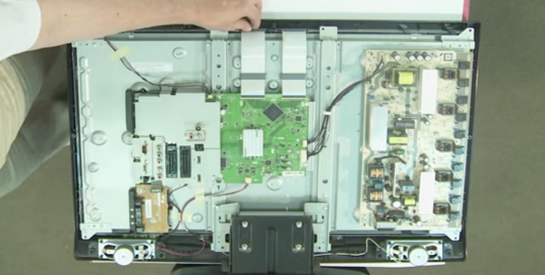
All TV sets are the same in their structure and consist of a power supply unit (PSU), a motherboard and an LCD backlight module (lamps are used) or LED (LEDs are used). It is not worth repairing the motherboard on your own, but the power supply unit and screen backlight lamps are quite possible.
As already mentioned, the design and principle of operation of LED and LCD TVs, regardless of the manufacturer, are the same. Of course, there are some differences, but they do not play a significant role in the diagnosis of faults. Often, in the event of a problem with the power supply, the LCD TV does not turn on at all, while there is no indication, or it turns on for a while and turns off spontaneously. Using an example, the repair of a DAEWOO LCD power supply unit (can be applied to plasma) is considered, which is not much different from repairing an LG TV, as well as Toshiba, Sonya, Rubin, Horizon and similar models.
- First of all, before you repair the TV, you need to remove the back panel of the device with a screwdriver by unscrewing the screws. On some models, the rear wall may be latches installedwhich must be handled with care so as not to break them.
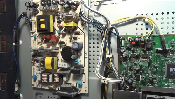
- After removing the cover, you will see the power supply unit, consisting of several modules on the left, and the motherboard on the right.
- On the power supply board you can see 3 transformers: the bottom one is the mains rectifier choke, the top one on the left (large) feeds the inverter, and on the right is the standby power supply transformer. You need to start checking with it, since it turns on the standby mode of the TV receiver.
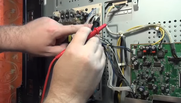
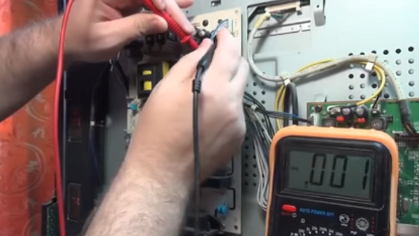
- Duty transformer when the device is connected to the network, it should give out a voltage of 5 V. In order to correctly find the wire on which you need to measure the voltage, you can use the diagram, or you can see the markings on the case. In this case, opposite the required contact is written - 5 V.
Measurement is taken first open circuitby connecting one probe to the found contact, and the other to the cathode of the diode on the radiator. In this case, there is no break.
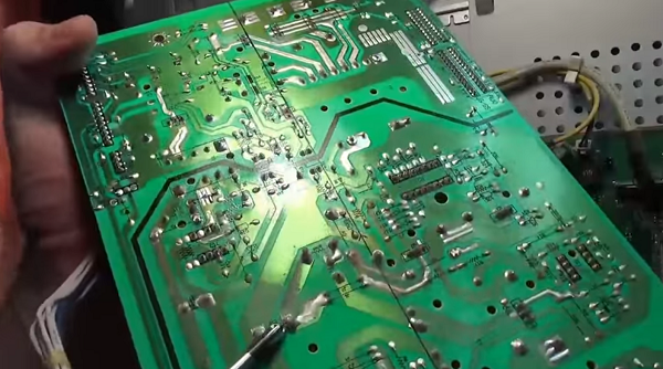
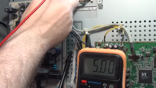
As you can see from the review presented above, repairing TV power supplies with your own hands is not such an overwhelming task. Following this description, you can also repair plasma TVs.
Do-it-yourself TV repair with a kinescope, for example, such as: Rubin, Horizon, Sharp 2002sc, LG TVs, as well as repair of the Vityaz TV, begins with checking the power supply unit for operability (this is done if the unit does not turn on). It is checked using incandescent bulbs for 220 V and a power of 60-100 W. But before that, be sure to disconnect the load, namely the horizontal output stage (SR) - connect a lamp instead. The CP voltage ranges from 110 to 150 V, depending on the size of the tube. Must be found in the secondary circuit SR filter capacitor (its values can be from 47 to 220 microfarads and 160 - 200 V), which stands behind the SR power rectifier.
To simulate the load, you need to connect a lamp in parallel to it. To remove the load, for example, in the popular Sharp 2002sc model, it is necessary to find and unsolder the inductor (located after the capacitor), the fuse and the limiting resistance through which the CP stage receives power.
Now you need to connect the power supply to the power supply unit, and measure the voltage under load. The voltage should be between 110 and 130 V if the CRT has a diagonal of 21 to 25 inches (as in the 2002sc model). With a diagonal of 25-29 inches - 130-150 V, respectively. If the values are too high, then it will be necessary to check the feedback circuit and the power supply circuit (primary).
It should be noted that electrolytes dry out during prolonged operation and lose capacity, which, in turn, affects the stability of the module and contributes to an increase in voltage.
When the voltage is too low it is necessary to test the secondary circuits to exclude leaks and short circuits. After that, the diodes for the protection of the power supply of the SR and the diodes for the power supply of the vertical scan are checked. If you are convinced that the power supply unit is working properly, then you need to disconnect the lamp and solder all the parts back. This check can also come in handy when doing DIY Philips TV repairs.
Another common breakdown of the TV that can be eliminated is the burnout of the backlight lamp. In this case, the TV receiver, after switching on, flashes the indicator several times and does not turn on... This means that after self-diagnosis, the device notices a malfunction, after which the protection is triggered. That is why there is no image on the screen.
For example, a Sharp LSD TV receiver with this malfunction was taken, although in this way it is possible to repair Samsung TVs, Sony Trinitron, Rubin, Horizon, etc.
-
To fix the TV, you need to remove the back cover from the TV. This requires a screwdriver or screwdriver.
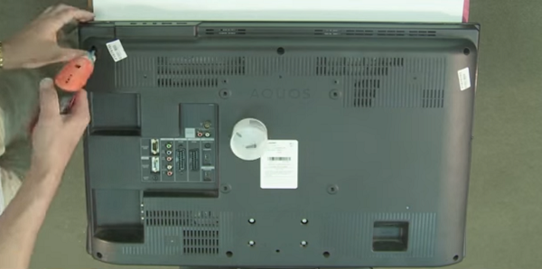
Next, you need to be careful disconnect loops from the matrix.
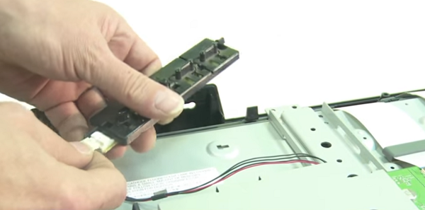
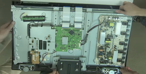
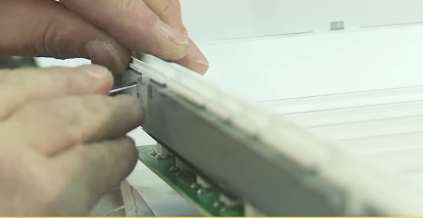
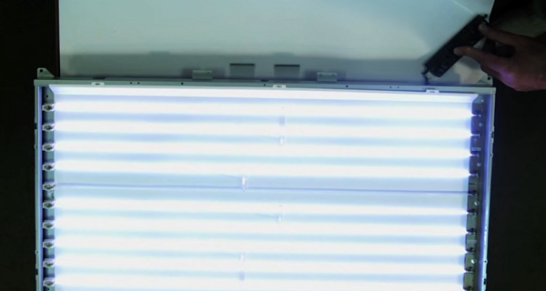
Thus, you can repair the Philips and LG TV with your own hands, and other LCD panels, as well as devices with LED backlight (LED). Owners of the latter type of devices should read the article on repairing LED backlighting, where the whole process is described in detail using the example of an LG TV.
Among the typical and simple reasons that the TV set does not turn on, there may be a remote control or a lack of signal from the antenna cable.
If the TV does not turn on with the remote control, first, you need to make sure the batteries are good. If they are shrunken, replace them. Often the TV set cannot turn on due to contamination of contacts under the buttons. To do this, you can disassemble it yourself, and clean the contacts with a soft cloth from accumulated dirt. If your remote control has been dropped, it is possible damage to the quartz emitter... In this case, it must be replaced. Well, if you filled the remote control with water or some other liquid, and it did not work after disassembling and drying, then it will have to be replaced with a new one.
You can learn more about fixing the remote control in the following video or article.
When repairing TVs LG, Sharp with LCD, Rubin, Horizon with the same screens, a situation often arises when it does not turn on when the device is in good working order. It turns out that the reason may be no TV signal in the antenna cable. This happens due to the operation of the noise suppression protection (in Rubin TVs, they began to install it not so long ago), and the unit goes into standby mode. Therefore, if you find your TV set inoperative, you should not panic, but you need to check the presence of a signal from the transmitting station.
In conclusion, we can say that when you decide to repair a TV set yourself, you should soberly assess your abilities and knowledge in this matter. If you do not feel confident, then it is better to entrust this matter to a telemaster, especially since nobody canceled 220 V, and ignorance of basic safety rules can entail unpleasant consequences.
| Video (click to play). |


