In detail: do-it-yourself repair of fuel pump d4bh from a real master for the site my.housecope.com.
Diesel operator, namely Comrade Barmaley, at my request, strangled the supply of diesel fuel to the injection pump ... This did not affect the flow rate, but the Insect stopped driving from the word "completely" ...
The malfunctions were eliminated, the fuel consumption returned to normal, but the patient still did not go ...
The other day I visited Barmaley again with the aim of: strangling the pump.
How he drove ... no, he didn’t! rushed! Again he began to squeeze into the seat, again the dynamics and throttle response returned ...
But the happiness was not long ... Having dashingly and quickly rode the day, the cockroach was warmed up ... No, it was not overheated, but the temperature arrow went to the middle, and the "dzhekichan" caught fire ...
I look into the radiator - I can't see the antifreeze ... I'm scratching my turnips ... well, then I'll find the antifreeze in the oil: I take out the dipstick, and there is less oil than the minimum, only at the tip of the dipstick ...
... this is for money, thought Stirlitz ...
I added a liter of oil, the level went to a minimum ... a liter of antifreeze ... leisurely, and carefully looking at what was happening, I traveled for another day - the oil remained at the same level, another liter was added with antifreeze ...
Aphids ... in the evening of the second day I started to change the oil, because it's time ... I bought a 6 liter canister of semi-synthetics, Kixx 5W30, which I was pouring before, I had to take the filter with Parts Mall PBA-010, because only he was available in the store ...
As usual, I drain the oil into a basin, remove the air filter box, then the first alarm bell rang out: the entire pipe between the filter and the turbine is already oozing with oil ... in the lower part it liquefied, and it burst along the seam ... 15 millimeters crack ... the whole turbine in shit ...
I grab the oil filter with my hands, and it’s in even more shit than the turbine ... Well, what can you expect, it’s standing under the turbine ... I put my hand into the turbine, I begin to move the impeller, and here it rang alarmingly so that my ears were already blocked ... and the radial backlash is such that the impeller knocks ...
| Video (click to play). |
A cash register clinked in my head, beating a check for thirty ...
I collected everything back in a depressed mood ... As a result, I broke the front bolt of the air filter box (there is no such bolt in the catalogs (28171E)), after which I rolled my head to the clamp that holds the burst pipe on the turbine ...
Club forum for owners of minibuses HYUNDAI STAREX, H-1, GRAND STAREX
Message: №1 Alexandr_93 »30 Nov 2014, 08:47
Message: №2 arival52 »30 Nov 2014, 09:31
Message: №3 Alexandr_93 »30 Nov 2014, 09:55
Message: №4 arival52 »30 Nov 2014, 10:17
Message: №5 Alexandr_93 »30 Nov 2014, 11:01
Message: №6 serg66 »30 Nov 2014, 11:09
In this picture, it is numbered 240, a wire fits to it under a nut and closes with an elastic band.
Message: №7 Alexandr_93 »30 Nov 2014, 14:02
Message: №8 arival52 »30 Nov 2014, 19:42
Perhaps WRONG, because VALVE SPILL CONTROL - instead of a cut-off sensor, it is screwed into the “plunger pair” according to the diagram,
looks like this.
I thought that there is a valve on the D4BN, it doesn’t look like it looks from the pictures.
I climbed for a long time and I can be wrong.

Message: №9 455651 »30 Nov 2014, 22:35
P.S. "The overwhelming majority of diesel products from the Korean manufacturer Doowon (partly owned by Robert Bosch GmbH) are licensed reproductions of the corresponding Zexel products."
P.P.S. catalog numbers of main spare parts for pumps 33105-42800 33105-42710 33105-42730
plunger pair 146403-9620 (9461626030)
spring 146232-0320 (9461610127)
roller 146210-5720 (9461616128)
roller ring 148210-0120 (9461615944)
cam washer 146220-2120 (9461614976)
rem. set of gaskets 146600-4620 (9461617567)
Message: №10 455651 "02 Dec 2014, 14:46
Message: №11 Alexandr_93 "07 Dec 2014, 17:46
Message: №12 FROST "12 Jan 2015, 16:25
Message: №13 455651 »04 Sep 2015, 14:57
Message: №14 igor309 »09 Feb 2016, 19:08
Message: №15 455651 »09 Feb 2016, 23:06
Message: №16 arival52 »09 Feb 2016, 23:20
Message: №17 igor309 »10 Feb 2016, 11:42
Message: №18 455651 »10 Feb 2016, 15:51
Message: №19 igor309 »10 Feb 2016, 21:32
So well, that's what it was. The mark on the knee slipped 4 teeth.
So it didn't work as fast as a hood cable.
Here I post a video of the launch on the cold one.
Something is wrong with the moment of injection.The car shakes at low and high. Gray smoke. Idling is low. Almost stalls.
I understand that the ignition is late. So you need to move the pump counterclockwise?
I found interesting material on the Internet, according to the prompts, I adjusted it myself after accommodating the vaunted masters and felt the result immediately.
Maybe someone will also come in handy.
So :
Left wing view:
Windshield side view:
You need to start doing something with the injection pump by flushing it. Here are the links for flushing the injection pump.
https://my.housecope.com/wp-content/uploads/ext/3433/bbs/phpBB2/view. hp? t = 14403
... ntry432483).
If the tank and in general the entire fuel system is clean enough, flushing can be omitted, but periodically add a nozzle cleaner directly to the tank. They say it's not worse if you use it periodically. If the tank and the pipes are full of dirt, we will clog the nozzles nafig. And no filter will help.
Before getting upset about the poor performance of the injection pump, you need to pay attention to the EGR valve. The valve bypasses part of the exhaust gases to the suction. About whether he should or not have written enough. But you need to try to turn it off - sometimes the engine is fully restored and you don't need to touch the high-pressure fuel pump. Well, then everyone decides for himself to ride with or without him. I muted it, and then deleted it altogether.
Also, with a worn out engine, we try to disconnect the crankcase ventilation tube from the suction. Close the suction hole with a plug. Sometimes after that the engine is not recognized.
Further it is recommended to do the following: Unscrew bolt 14. Do not lose 2 copper rings. Although it is better to replace them with new ones. The bolt is on the fuel drain. It has a tiny little hole on the side. To prevent debris from getting into it, a mesh is installed in the bolt. In kerosene from the mesh with a brush, wash out the debris.
Idling adjustment screw 1. You can turn it boldly and without remembering how many revolutions. The risk of misaligning something is minimal, but it is possible that due to the knocked down other adjustments, it will not be possible to set the required speed. (In this case, we are taking the injection pump to the stand to regulate). We adjust on a hot engine. Revolutions - 750-800 rpm (the first division on the tachometer is 0, the second is 500, the third is 750, the fourth is 1000). Air conditioning and other crap everything should be turned off as much as possible. In this case, the vacuum regulator 9 should not tighten.
On some injection pumps, screw 1 was installed not where it is in the picture, but behind the injection pump. But he presses on the same lever and the adjustments are the same.
Regulator of increased idle speed 13 (fast XX regulator). With the air conditioner turned on, the automatic transmission torque converter, etc., with screws 2 and 3, set the speed of XX to 1100 rpm. If the gearbox is mechanical, up to 900 rpm is enough. We do it on a hot engine. The adjustment is very simple and it was not necessary to remember how it was. According to the rules, with clutch 2, we bring the traction almost close to the lever with the engine stopped (clearance is about 1 mm), and with screw 3 we adjust the speed. The diaphragm in the regulator 13 sometimes breaks. In this case, you can drive perfectly for a while, if you increase the speed of the twentieth century with the already known propeller 1. I drove without this regulator, and on the new injection pump it never was.
Screw 9 - screw for adjusting the maximum speed. It is hardly necessary to regulate. It is necessary to check, when the pedal is fully depressed, whether the lever 10 rests against the screw 9. The screw is responsible and it is hardly worth turning it. Actually, if we twist it, then we simply will not press the gas to the end as it was before. If the lever 10 does not reach the screw 9, then adjust the cable. This is already simple and I will not describe it. If according to the rules, then when the gas pedal is fully depressed, the revolutions at XX should increase to 4200. You can adjust it this way.
Screw 8 - screw for maximum fuel supply. The screw is EXTREMELY responsible. By twisting it, you can completely ruin all the work of the injection pump. In addition, it must be twisted by a fraction of a turn. Plus, it's hard to get to. Unscrewing the screw, we move the plunger drain ring to the right, thereby reducing the fuel supply.For example, when the turbine does not develop pressure, but we continue to drive, the screw can be unscrewed a little. Black smoke will disappear under heavy load, fuel consumption will decrease, and it will still be equally bad to pull the engine. With a sharp press on the gas pedal on the XX, a light cloud of black smoke should appear from the exhaust pipe, and then the exhaust is absolutely clean. This is optimal.
If there was a dirty antifreeze, the regulator 12 could get clogged with dirt. In this case, when the engine warms up, the increased speed will be kept for a very long time. We remove the tubes from it (antifreeze will flow!) And blow it with air.
INJECTION ANGLE ADJUSTMENT
The initial angle of the moment of fuel injection is adjusted by loosening the injection pump mounting bolts and turning it. For this injection pump, the injection moment is regulated by the indicator according to the instructions. The adjustment is standard and is described broadly in the instructions. Since the engine is not new, we make the injection angle a little earlier.
And in order to return the pump to its place after scrolling, initially put a small chisel on the injection pump and the mounting bracket, drip white paint and wipe it off. This will always allow you to restore everything as it was.
There is one more tricky screw 11. It stands on the device that adjusts the injection advance angle on a cold engine. The injection angle also depends on the position of the screw 11. By unscrewing the screw we obtain an earlier feed. The operation of the device is carried out using a cylinder 12, from which, when heated with antifreeze, the stem extends. At -20C and below, the injection angle will be as early as possible. When heated from -20C to + 50C, the injection angle becomes more and more late. The maximum late angle is obtained at + 50C and does not change further. At the same time, this device increases engine speed at low temperatures. The screw 11 can also adjust the initial angle of the moment of fuel injection. But by adjusting the injection angle, we will knock it down on a cold engine. Therefore, you can use it just to try to change the injection angle. This is convenient, since you can do everything without even turning off the engine. Then we restore everything and change the injection angle by the position of the injection pump.
In general, this problem was not only mine. And no one could really decide.
So. It's been almost 3.5 years since I bought Galloper. The maximum speed was 110 km / h. This is the limit. Turnover - 3100-3200. Even at idle speed above 3500 it was not possible to get it. BUT! At lower revs, everything was fine. And since I didn’t want to go fast, I didn’t look for a reason.
And now I have flushed the injection pump. Soon there was a terrible air leak through the fuel filter (not connected with flushing). The filter was replaced in a set from a Ford Mondeo 1.8TD. And he also hounds. I bought a repair kit for it. I've done everything. There is no suction anywhere. MAXIMUM SPEEDS at idle fell after that to 2500. You accelerate quickly - and then stop.
Having climbed the Internet, I found a discussion on some forum. I didn't take my own photos, but stole 2 photos from there. I think that they will not be offended, since it is written there that they want to lay out for the Gallopers.
So. The reason turned out to be small, very small. There is a bolt at the entrance to the injection pump. We wash everything around from dirt. We unscrew it:
At the same time, we do not lose 3 copper rings. Along the way, we will unscrew the clamp that secures the fuel supply pipe to the injection pump. To take this tube aside. We will take the copper rings home, heat them on gas until they are red and immediately throw them into cold water. They will become soft. Or buy new ones. With new ones, it is desirable to also perform a similar procedure.
We remove the spring from the hole.
In the depth of the hole (cm 5 from the surface) there is a small mesh. You can remove it either with a stick with cotton wrapped around it. Or, what is better, we take a stranded wire, expose the veins by 7 mm. We unbend them. We insert it inside and extract it together with the mesh:
We wash the mesh, blow it through. Fig it is cleared. Therefore, after that we carry it to the gas. We anneal a little. And again we rinse, blow through. Everything is clear.
Putting everything into place.The whole procedure was done under my window in the courtyard + in the apartment. It took about 20 minutes. I went. You can't recognize the car. The beast! In addition, the tapping at 3000 rpm disappeared.
Why does so much depend on this mesh? She stands at the entrance to the injection pump. When it becomes clogged, the injection pump begins to suck air through its seals. At low revs, it does not suck. At high vacuum, the vacuum is higher and the suction has gone.
The high pressure fuel pump has a centrifugal speed controller. It is located under the top cover. When cranking with the starter, it keeps the fuel supply at maximum. When working on the XX, it maintains the speed. If the engine is cold and the rpm is low, the fuel supply is automatically increased. If we turn on the air conditioner, the speed also drops. The regulator increases the fuel supply again.
Well, it looks like this. We turned on the air conditioner - the speed dropped slightly (it was almost not noticeable on the tachometer) and the engine continued to work as if nothing had happened.
And the vacuum regulator, when the air conditioner is turned on, additionally increases the speed. The air conditioner at XX begins to cool a little more. well that's all.
In general, I do not see any need for a vacuum regulator. Poorly justified complication of the design. I completely removed this system, including the pneumo-electric valve. BUT THAT'S MY PERSONAL OPINION. THIS TOPIC WAS A DISCUSSION. It is believed that without a vacuum regulator, the speed drops strongly. I don’t know who’s right. See for yourself. And for myself, I decided.
And removed the valve from the USR. I have no valves at all now. From the vacuum pump, the tube goes to the brake booster. No bends.
And where does the valve cover? I advise you to wipe the headlights and kick the wheels; D
“D4BH mechanical injection pump, some kind of hatch. " -Nichrome is not clear. Car model, year, displacement, fuel pump no. - into the studio! (a portrait of the "hatch" in full face is also possible); D
And where does the valve cover? I advise you to wipe the headlights and kick the wheels; D
“D4BH mechanical injection pump, some kind of hatch. " -Nichrome is not clear. Car model, year, displacement, fuel pump no. - into the studio! (a portrait of the "hatch" in full face is also possible); D
In the first case, by the way, they are not small.
In our city there are about three hundred diesel engines, all of them have a bad reputation, and every one hundred says that everything is being redone after the others. Ie some hayut others. I don’t mind the money, I’ve probably spent an extra hundred thousand on the salary. I just don’t see a way out, so I’m trying to somehow understand what happened, I can advise the masters what.
I, too, sit on a thematic forum in my profession and send such vlppros providers (which I myself am now) to the masters, tk. Everyone must do their job. But this is only in those cases when a person decided to save money and cheat on my brother's earnings. In my case, there is no way out. The car is at a standstill, my work is at a standstill, all plans have collapsed, there is no way to see it.
This is very clearly visible on the stand. You spin the high-pressure fuel pump at a speed higher than idle. You press the gas lever. Letting go of him. If there remains a “dripping” of fuel through the test injectors, then this is it.
The D4BH engine was created by the Kia-Hyundai concern by analogy with the 4D56T engine manufactured by Mitsubishi. It is originally a turbocharged diesel engine for longitudinal positioning under the hood. On some trucks, access to it is from inside the cabin, which makes maintenance easier, but makes it difficult to dismantle during a major overhaul.
The cylinder block and exhaust manifold in the D4BH engine are made of cast iron. The intake manifold and the cylinder head are aluminum. The 4-cylinder in-line engine provides 2.5 L combustion chamber volumes with a 91.1 mm bore and 95 mm stroke.
D4BH stands for:
- D4B - series;
- H - turbine plus intercooler.
There are atmospheric modifications of the same D4BA and D4BB series, turbocharged, but without the D4BF intercooler. Depending on the turbine, forcing allows you to get different values \ u200b \ u200bof the parameters of a diesel internal combustion engine:
- 716938-5001S - it was necessary to increase the power to 140 liters. sec., was used in minivans of the Hyundai H-1 plant;
- 49135-04300 - 99 HPwith., installed by the manufacturer on minivans H-1;
- Electronic 715843-5001S - 136 HP with., operated with the TCI system in the Korean minivans Starex;
- 716938-5001S - 140 HP pp., the manufacturer recommends this configuration for Starex minibuses;
- 49135-04300 - 99 HP sec., for Starex 2.5 TD;
- Electronic 715843-5001S - 136 HP with., modernization by the TCI system for the minibus H-1.
In different configurations, in addition to the turbine, attachments may differ - an oil pump, an intake manifold. Until 2001, a mechanical injection pump was used, then with electronic control.
The most important technical characteristics of the D4BH are summarized in the table:
combined cycle 15 l / 100 km
clutch bolt - 15 - 22 Nm
bearing cover - 75 - 85 Nm (main) and 45 - 48 Nm (connecting rod)
cylinder head - 115 - 125 Nm
The characteristics of the engine are regulated by using different turbines, injection pump designs and intake manifold.
Initially, the D4BH engine has the following design features:
- cast iron cylinder block with liners;
- lightweight aluminum alloy cylinder head;
- a pair of belt-driven balancing shafts to reduce vibration loads;
- a five-bearing crankshaft made of forged steel, fillets are hardened using knurling technology;
- cast aluminum piston complete with a special coated compression ring;
- valve opening angles correspond to 20 and 55 degrees before TDC (inlet, outlet, respectively), closing angles - 49 and 22 degrees;
- vortex combustion chambers, cast camshafts;
- The injection pump and the timing belt are driven by a common toothed belt;
- The adjustment of the thermal clearances of the valves until 1991 was carried out with washers, then with pushers of different lengths, the description of the operation is included in the user's manual;
- the oil filter is placed on an individual bracket;
It is quite possible to carry out a major overhaul with your own hands, but there are some nuances of the complete set. For example, D4BH and D4BF oil pumps are outwardly similar, but differ in the location of the generator bracket. If they are confused, the alternator drive belt will break immediately after repair, as the crankshaft and alternator pulleys will not be aligned.
Conventionally, several variants of the same series can be attributed to the varieties of the D4BH motor:
- D4BF - no intercooler
- D4BA - atmospheric modification;
- The D4BB is the same naturally aspirated version, but the volume has been increased to 2.6 liters.
Each of these modifications uses its own attachment, which is not suitable for the basic version.
An unpleasant feature of D4BH diesel engines for owners is the belt drive of the balancing shafts with a low service life. The second problem is the vacuum pump, or rather the cutting of the splines on the generator shaft by this part, the broken rear bearing.
For the rest, the diesel engine does not cause trouble to the owners, it is considered very reliable and resourceful. On average, major repairs are carried out after 350,000 kilometers. For D and E class cars, fuel and lubrication consumption is quite economical.
The manufacturer has implemented the D4BH engine as a power unit on the following Hyundai vehicles:
- Terracan - station wagon with front / all-wheel drive;
- Galloper - SUV;
- Porter - a commercial truck with access to the engine from the passenger compartment;
- Porter II - a truck with an improved cab design;
- H-1 / Starex - LVC minivans;
- H-1 / Grand Starex is a minivan for the Korean domestic market.
It is also recommended by the manufacturer's design department to use these engines in Kia Bongo / K2500 trucks.
The official manual for the D4BH diesel engine regulates the following maintenance periods:
- oil change every 7500 mileage with oil filter;
- the timing belt has a resource of 80,000 km, and the check is carried out twice as often;
- the attachment belt is capable of departing 60,000 mileage;
- the fuel filter should be renewed after 40,000 km;
- the air filter is replaced every 40,000 mileage;
- antifreeze properties decrease sharply after 20,000 km.
A sufficiently compact ICE device inevitably leads to burnout of the exhaust manifold, therefore, after 30,000 km, it must be inspected, and changed about half as often.
Despite the reliable design and fairly high performance characteristics, the D4BH motor has the following "diseases":
3) development of the resource of the air filter
2) the USR valve gasket is torn
3) replacement of valve stem seals
It should not be forgotten that the piston bends the valve one hundred percent at the moment the timing belt breaks.When replacing nozzles, the manufacturer recommends checking at the stand both used and new products to make sure they are working properly.
Since the D4BH engine already has both a turbine and an intercooler, it becomes almost impossible to tune for it. A further increase in pressure, firstly, depends on the design of the turbine, and secondly, it sharply reduces the resource of the power drive.
In principle, the manufacturer of the D4BH engine is already tuning it at the factory, selecting a specific version of the turbine for a particular truck, minivan or SUV on which it is installed.
Thus, the D4BH engine from KMJ is a turbocharged in-line powertrain longitudinal arrangement for heavy vehicles in the Hyundai and Kia lineup. Basic characteristics are equal to 99 liters. sec., 2.5 liters and 230 Nm, respectively, with a compression ratio of 21 units.
What color is the smoke and in what modes?
In general, if the smoke is gray and smells like unburned solarium, while it works more or less normally with the glow plugs on, I would assume a very late injection.
When disconnecting the injection advance sensor (not the regulator) TPS (stands on the side of the injection pump perpendicular to the body) the computer averages the control data, hence there is no hard work of the engine.
Specify what exactly did you clean and how did you measure the duty cycle?
How was it measured and in what modes?
Smoke, gray, injection on the engine, yes, late. I am interested in such a question, why when I set 7 degrees. according to those data, does the engine smoke? The regulator turned off, which is located under the pressure valves - removed, checked - the worker. The duty cycle was checked with an oscilloscope. Injectors - were disassembled, cleaned, pressurized at the stand. The EGR valve, checked when disassembling the engine, and the timer piston for its mobility .Internal body pressure on H.H. pressure gauge, between the injection pump housing and the return valve. Now, temporarily made an injection by ear, about 2 degrees.
So in your case, what is the pressure at idle speed of the engine?
Smoke, gray, injection on the engine, yes, late. I am interested in such a question, why when I set 7 degrees. according to those data, does the engine smoke? The regulator turned off, which is located under the pressure valves - removed, checked - the worker. The duty cycle was checked with an oscilloscope. Injectors - were disassembled, cleaned, pressurized at the stand. The EGR valve, checked when disassembling the engine, and the timer piston for its mobility .Internal body pressure on H.H. pressure gauge, between the injection pump housing and the return valve. Now, temporarily made an injection by ear, about 2 degrees.
D4BH, this is an analogue of 4D56, which stands on Pajero.
4D56 is not on Pajero but on L 200 FOR CORRECT SETTING of the injection moment, the plunger must be set to 1.0 + - 0.03 is 9gr to TDC
HOW did you clean the nozzles, but the main thing is that you did not do the main thing at the nozzles, this is a spray if there is no spray, then how not to twist and you will have to contact the specialists
why on the same D4BH engine with the same nozzles and power, there are so many different injection pumps in the catalogs. In fact, there is only one injection pump, and they cost the same everywhere. More precisely, the "body" of the injection pump is the same, the only difference is in the wiring of the "spit" of the injection pump. There are three connectors on the injection pump spit, two small and one large. So there is a large connector for 13 contacts and sometimes for 12 contacts. That's the whole difference. Photos of connectors can be found on the website in the section of the Hyundai Kia injection pump. Well, the braid may also differ in the length of the wires.
4. Interchangeability.
Injection pump with numbers
Injection pump with numbers
33105-42820
33105-42800
33105-42730
33105-42720
braids identical in connectors, but different in length. TNVD 33105-42730 can be put in place of anyone, since it has a long braid.
If necessary, you can lengthen the braid and rearrange the connectors. So, in principle, if you want, you can interchange any D4BH injection pump, which we did.
Now we have on sale two types (by connectors) of injection pumps with a long oblique. If you need to choose a fuel pump for your car, just look at the center connector.Visually, the connectors also differ in that the 13-pin connector has fasteners for bolts, while the 12-pin connector does not.
On injection pump D4BH for Teracan and Galloper 12-pin connector
On injection pump D4BH for Porter Starex 13-pin connector
There is no more complex and critical unit in a diesel engine than the fuel injection system, more precisely, its main part - the high pressure fuel pump. Many mating parts, highly loaded units, the presence of a precision dosing system, make the repair of the injection pump a difficult task even in service conditions. It is all the more difficult to repair the high pressure fuel pump of a diesel engine with your own hands.
In automotive technology, almost everything is repaired, except, perhaps, individual oil seals and cuffs, the repair of which is impossible without special materials. The complexity of setting, diagnosing and repairing the injection pump requires the employee to have skills in working with precision mechanics.
It is simply impossible to adjust according to the factory parameters, without a special diagnostic stand for the repair of the injection pump. During the diagnostic study of the injection pump, it is necessary to check:
- cyclic supply of the high-pressure pump, in the entire range of revolutions of the injection pump shaft, at start-up, and after cutting off the fuel supply;
- stability of the developed pressure;
- uniformity of the injection pump delivery to the fuel injector.
Even having access to a diagnostic stand, and having studied the issue of repairing a high-pressure fuel pump using numerous videos, it is very difficult to qualitatively check and evaluate its work.
In heavy diesel engines, plunger, in-line injection pumps are used. In maintenance and repair, such devices are more difficult, since they require special equipment for its disassembly, therefore we will not consider such high pressure fuel pumps and their repair.
In a passenger diesel engine, a distribution type injection pump is almost always used. Unlike in-line pumps, in a distribution pump, the force is transmitted to the plunger using a profiled cam washer. The design of the injection pump turned out to be more compact, but it is hardly simpler to expect to carry out its repair on the knee.
The most famous and affordable is the Bosh VP44 injection pump. Often, the need to repair the pump internals arises when:
- poor traction and incomplete combustion of fuel even under ideal conditions - in the absence of load and a thoroughly warmed up engine;
- a sudden failure and stoppage of a diesel engine under load, which is called “death on takeoff”. Usually the scanner in such cases diagnoses the code P1630 and P1651.
- the appearance of a diesel fuel leak in the area of the gland seal of the central shaft of the injection pump.
Therefore, we will restrict ourselves to the issue of repairing the injection pump with our own hands by replacing the seals and eliminating the scoring of the working surfaces of the parts.
Before disassembling the pump drive shaft seal, try to move it radially. If play is felt with your hands, it is possible that the reason for the leakage of fuel is the wear of the working surface of the shaft or requires repair of the bearing.
A large number of split planes and mating surfaces of parts required the use of a large number of seals and glands. As a rule, they are made of quality material and last long enough until they are damaged during repair or maintenance. In this case, standard repair kits are used for DIY repair of Bosch injection pumps.
It is quite easy to replace the seal on the shaft position sensor and on the automatic injection timing during repairs. For a better fit, you can drip a few drops of spindle or engine oil onto new rings and rubber bands.
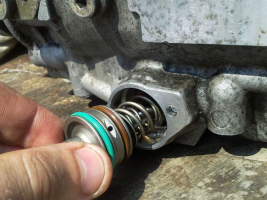
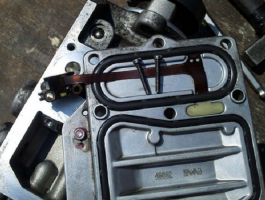

For preventive repair of a Bosch injection pump with your own hands, you will need to disassemble the pump in approximately the following order:
- remove the metering valve from the end of the injection pump. To do this, unscrew the four screws of the pressure plate, carefully release the cable of the injection advance valve. By removing the three screws securing the metering valve, you can carefully remove it from the seat;
- by unscrewing the fastener on the top cover, you can remove the control board and gain access to the electronics;
- we set the position of the shaft, as shown in the photo, remove the camera and get access to the insides of the injection pump;
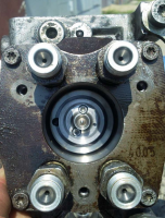
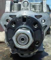

- after dismantling the bearing using a special puller, we get the opportunity to study the potential culprit for the poor performance of the injection pump - the piston of the injection advance unit. There is often surface wear and edge scuffing on the part. You can try to make repairs by polishing the surface, replacing the whole part is much more expensive.
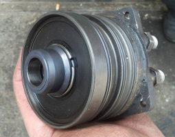
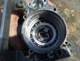

After the repair, the assembly is carried out in the reverse order with the washing of the parts with diesel fuel.
Often, in addition to scoring, on the surface of the pistons there is another reason why the injection pump does not develop the required pressure. This can be due to debris, films or wax build-up on the filter screen inside the pump. There is a mesh on the side of the inlet pipe. Rinsing the channels is a troublesome and ineffective business, it is easier to remove the mesh and blow it with compressed air.
Torn pieces of debris can jam the plunger piston or even break or break the pump drive shaft. Therefore, cleaning should be done very carefully to avoid contamination of the internal cavities of the pump.
Among the many reasons for the failure of the electronic "liver" of the injection pump, the most common is the breakage or burnout of the contacts of the control board and the failure of power transistors. If the knowledge and skills of working with electronic devices allow to carry out a "continuity" of the transistor performance and repair, it is worth trying to identify the cause and replace the culprit with a serviceable element.
To check the condition of the "culprit", you need to carefully open the black cover, which is tightly seated on the rubber seal with screws. It should be removed carefully so as not to damage the seal itself.
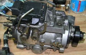
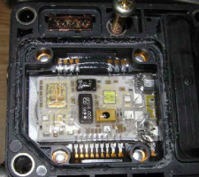

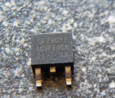

The reason for the failure of not only the transistor, but also the entire board could be air trapped in the cavity due to poor performance of the drainage system or the check valve. Often, they try to eliminate the airing by spinning up with a starter, hoping to pump diesel fuel into the high-pressure fuel pump in this way. At this moment, the transistor is open and loaded as much as possible, which leads to intense heating. In an air environment with poor heat dissipation, it will inevitably burn out. In some German cars there is a protection that prevents an attempt to start the engine in the absence of fuel in the highway. For this, a fuel sensor in the tank is used.
Failure of the transistor can be established by "dialing" a tester or by its appearance. The best option for repairing such a malfunction would be to replace the entire control board. Perhaps it is more expensive than soldering, but it will give guaranteed quality and stable operation of the injection pump after repair. As a last resort, give the board and the transistor for soldering to electronics specialists.
When installing and reassembling after repairs, check the tightness of all fasteners.
If during the audit you did not make rash and unreasonable replacements of parts, the assembled pump should work with approximately the same parameters as before. Bosch EPS-815 stand is used as a standard for testing and adjusting injection pump after overhaul.
The video shows how to raise the plunger pressure in a Bosch VE injection pump:
Attention, the editors of the site "Your Road" recommend that you consult with a specialist before applying this instruction to action.
One of the most mysterious parts of a car with a diesel engine is a high-pressure fuel pump (TNVD). There are 2 types of pumps - a mechanical pump and an electronically controlled pump, popularly EFI-shny. Each of the types is divided into 2 subspecies: Multi-plunger in-line, single-plunger distribution type (VE). We will not consider the "exotic" type of pump-injector, Common Rail or VR series distribution pumps (Distribution pump with axial plunger, Distribution rotary injection pump)
Since the device, and therefore the principle of its operation, is a mystery for many, there is an opinion that specialized equipment and a specially trained person are needed to repair it. However, such a "gentleman's" set is not always at hand, so let's try to disassemble and assemble this tricky knot "on the knee". The object for preparation will be a high-pressure fuel pump, assembled in ancient times from several different-sized pumps, without using stands, but at the same time successfully spinning a 4D56 diesel engine WITHOUT TURBINE up to 8000 rpm. Externally from the high pressure fuel pump installed on your car, it can differ only in the absence of a pressure corrector (a kind of mushroom hat on the top cover) and some attachments. This does not change the essence of the matter.
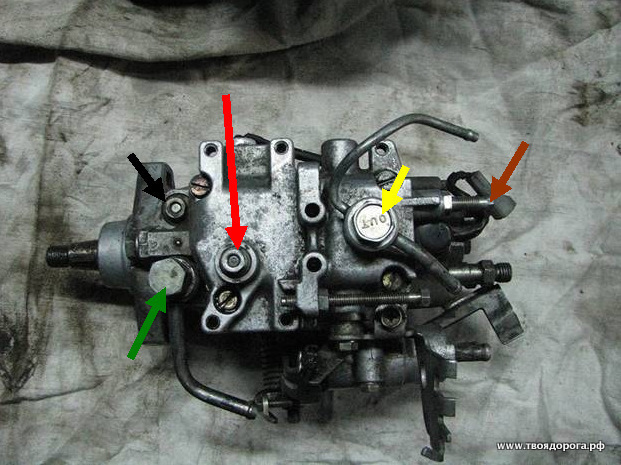
So, on the table- OH .. Top view
Colored arrows indicate:
- Green - fuel supply bolt
- Yellow - "return"
- Black - pressure valve in the injection pump housing
- Red - the axis of the fuel supply regulator ("gas" drive). The "gas" lever itself has been dismantled for convenience.
- Brown - mixture "quality" bolt.
Arrows indicate:
- Black - automatic heating
- Green - drive of the automatic heating device
- Red - automatic ignition timing (injection)
- Blue - identification plate
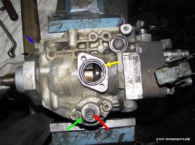
Side view (back side):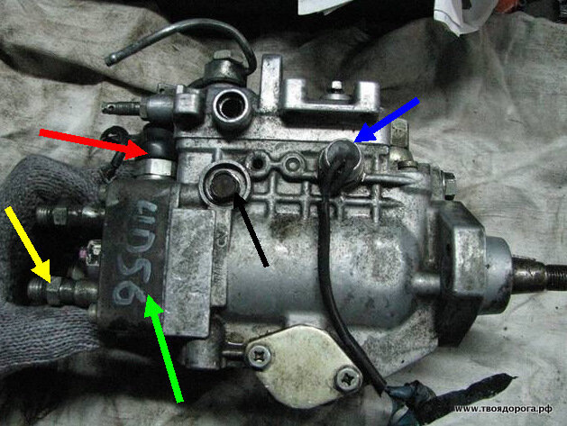
- Blue - speed sensor (tachometer, not always present)
- Red - fuel cut-off valve (muffler)
- Yellow - pressure valve.
- Green is the plunger itself.
- Black - the axis of the fuel lever. The same is available on the back of the pump. It is better to remove (but not completely unscrew) them at the initial stage of disassembly.
For work you will need: a set of heads, a set of hexagons, tweezers, screwdrivers, a gas wrench, a caliper, a vice, a clean rag, a container with clean diesel fuel, a grease (Litol, CV joint, etc.) -))
- A mesh filter is installed inside, which, as a rule, cannot be washed. Removal has no “contraindications” (yellow arrow).
- Has a calibrated hole on the lateral surface (red arrow). Different pumps have different sizes, so replacing them with another leads to a change in the internal pressure in the pump.
I think no comments are needed. Council - the drive itself should not be disassembled.
- Yellow - speed sensor
- Green - "jammer".
- Black - centrifugal speed controller.
- Blue - fuel drive lever.
Here one difficulty is to get to one of the 3 bolts. There are only two options:
Disassemble the drive (carefully, there is a powerful spring! + REMEMBER the setting of the adjusting bolt), and then calmly unscrew the rest.
Unscrew 2 "light" bolts under the key "by 10", loosen the third, "heavy" one, and pushing the assembly aside, slowly unscrew it.
It should look like this:
- Yellow - O-ring
- Red- adjusting bolt of the automatic advance switch
- Green - the cover of the advancing machine.
- Remember (write down) the bolt head protrusion (red arrow) above the cover (green arrow). If in the process you decide to unscrew this bolt, during assembly it will be necessary to return the dimensions to their original state.
- Blue - the axis of the speed regulator.
- Black - mating plane.
Attention! For pumps with RIGHT rotation, the thread on the shaft will be LEFT and vice versa!
If you can find a tool, unscrew the pressure regulator.
Now the fun begins. Parsing includes nodes consisting of several parts. Moreover, the details cannot "live" without each other. That is, they simply cannot be confused with each other.
- Red - pressure valve body
- Green - spring returnable
- Blue - valve needle
- Yellow - valve seat
- Black - sealing washer.
The plug under the red arrow does not need to be unscrewed; it serves to install the indicator. The fact is that the ignition on diesels is placed not so much on the marks. Rather, initially, the moment of injection is set according to the indicator, and only then the mark that we see is applied. We will omit this procedure for now, the turn will come to it.
So, turn off the cap (blue arrow). This is where the gas wrench comes in handy. The thread of the plug is right-hand.
- Blue - plunger body
- Red - plunger.
At this stage, it is necessary to measure the amount by which the plunger sinks into the body. We measure the results, write them down, they will come in handy during assembly.
We release the fastening screws (but not completely), and gently shaking, we move the plunger body up. As soon as it is free, we finally unscrew the screws and remove the plunger body. You should get the following picture:
- Blue - plunger
- Yellow - dosing ring
- Red - washer - bearing
- Brown - base plate
- Black - spring
- Green - adjusting washers.
- Black - Plunger Shim
- Red - cam washer.
- Green - fuel delivery lever. I managed to take it off earlier.
Attention!! We do not remove the videos, we do not change them in places.
Remove the stopper (shown with a screwdriver).
We see a pin under the stopper. Shown also with a screwdriver (it is magnetized, the pin can be easily removed by it).
Remove the cam washer drive.
In the interior of the vacated space, push the axis of the advancing automaton:
For convenience, I deleted 1 video, there is nothing criminal here. Pull the roller ring outward for the axis of the advancing automaton. Caution, do not use unnecessary effort! At the slightest misalignment, the ring wedges in the body. Attempts to pull it out "insolently" will end in disrepair - the pump casing will be scrapped.
It should look something like this:
For the 2 "horns" sticking out in the depths of the pump, we take out the pump shaft with the gear of the regulator:
We return to the "remains" of the pump:
We release the bolts (blue arrows) and take out the booster pump cover (red arrow).
We turn over the pump housing.
We remove the oil seal (shown with a screwdriver). Warning - don't try to save it, it won't work anyway.
| Video (click to play). |
As a result, a bare body with a bushing pressed into it should remain. Like this:

