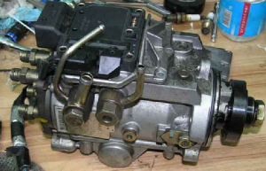
In detail: do-it-yourself pump repair 2ct from a real master for the site my.housecope.com.
T the high pressure dump pump is a very critical unit. The injection pump shaft is driven by a timing belt. The injection pump has many tasks and functions. Here are the main ones:
1. Supply of fuel under high pressure to injectors;
2. Change in the amount of injected fuel per unit of time at different crankshaft speed;
3. Cutting off the fuel by the solenoid valve when the engine is stopped;
4. Taking readings of revolutions (for a tachometer, etc.);
5. Correction of the amount of injected fuel when the turbine reaches operating speed (vacuum);
6. Heating control (at low coolant temperature, fuel supply increases);
7. Management of the number of idle speed (XX) in connection with the inclusion of an air conditioner, refrigerator (vacuum).
Also, the minimum speed of XX is adjusted, the maximum engine speed is limited. Adjustment of the nominal fuel supply, ignition timing ...
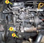
To replace the rubber O-rings, release the injection pump regulator lever. Unscrew the 4 hex screws (5mm) indicated in the figure on the left (item 1).
2 - Vacuum actuator for increasing the speed of XX in connection with the inclusion of the refrigerator, air conditioner or button for increasing the speed XX.
3 - Heating control (adding speed at low coolant temperature).
4 - Lever of the fuel supply control regulator.
1. Heating control device, disconnected from the injection pump by unscrewing three bolts;
2. O-ring at the point where the control arm enters
| Video (click to play). |
3. Internal lever; setting an earlier injection;
4. Setting the speed during warming up;
5. Lever for increasing revolutions, outside;
6. Connecting the temperature sensor to the coolant circuit.
1. Cover of the boost pressure corrector;
2. The oil seal of the regulator lever, it is from this place that the fuel sometimes seeps;
3. The screw for adjusting the nominal fuel supply, after adjustment at the stand - is sealed. If you uncontroll him, you can change the cyclic fuel supply with the adjusting rod, - unscrewing it - we decrease the flow, screwing it in - increase... Without knowledge and experience, we do not recommend touching it, since there is a high probability of engine stalling, increased smoke, poor speed drop. If, nevertheless, when adjusting on a running engine, you overdo it, and the engine starts to pick up speed, urgently unscrew this screw a couple of turns back.
At this point, indicated by the arrow, the governor shaft engages with the governor levers. The regulator shaft is removed from the lever system precisely through this groove, which allows the top cover to be disconnected from the injection pump housing (shown in the figure below).
Carefully remove the axis of the regulator lever from the pump cover. In the event of fuel leaks, as well as after disassembly, it is imperative to replace the annular rubber seal ring on the regulator axis and the oil seal installed in the high-pressure fuel pump cover in the place where the regulator axis comes out.
Consider the operation of a high pressure fuel pump.
Turning the injection pump with the drive down, remove the unscrewed head of the fuel pump. This is done so that the springs, rollers with washers do not fall out.
After all, every detail has its own worn-in place, this must also be remembered and everything must be laid out correctly during disassembly, so that later it is correctly assembled. In the figure on the left, yellow arrows show rollers with washers (installed on the outside of the roller, with the roller washers facing the rollers).Each roller is in its own seat, it is they who are subject to strong mechanical stress, and have significant performance in the "running bass".
Remove the clip with rollers carefully so that they do not fall out! And you cannot change the location of the rollers in the cage, this also applies to the washers.
From the timing belt, torque is transmitted to the cam washer through an adapter (spring clutch).
The spring-loaded mechanical contact forces the plunger to move progressively along its axis and, at the same time, also rotate. Numerous channels are located in the injection pump head, and the pump plunger has slots and through holes in its lower part. Thus, at a certain position of the plunger, the fuel is distributed at the outlet from the injection pump head.
As you can see from the pictures on the left, in the upper end part of the injection pump head there is a solenoid valve for the fuel cutoff.
This valve can be removed and tested separately by applying voltage from the battery (+ to the contact, - to the valve body). A characteristic click will be heard and the valve will retract into the core. Thus, when voltage is applied to the cut-off valve, the fuel supply channel opens, and when the voltage is removed, the fuel channel is closed by a rubber seal under the action of the closing spring. This locking principle is used in our minibuses to stop the engine. Without supplying voltage to this valve, it is impossible to start the engine, even if everything is in perfect order. This method is used by many anti-theft systems that are part of the alarms, built into the break of this control wire.
In the picture left we see a twisted solenoid valve:
1. Solenoid valve body;
2. Positive contact of the solenoid coil (the negative contact is fixed on the valve body);
3. A mesh filter installed at the inlet to the plunger.
As you can see, dirt settles on this small filter, which has passed with the fuel even through the main fuel filter, and somewhere the fluff from the filter itself. This filter prevents other debris from entering the fuel inlet into the plunger, thereby preventing rapid wear of precision surfaces from small debris.
To get this filter from the recess in the injection pump head, I advise you to use tweezers.
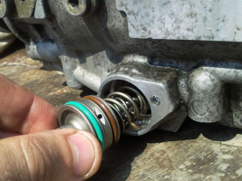
- Solenoid valve;
- Rubber sealing ring;
- Recoil spring;
- Core - valve;
- Rubber seal;
- Fuel mesh filter in the injection pump head.
Unfortunately, on the injection pump installed on the engine, access to this valve and filter is difficult, nevertheless, you will know about its location there! And if the fuel comes with difficulty, especially in winter it is clearly pronounced, you should ask a specialist at the service to clean this filter mesh.
- Installed tachometer sensor;
- Regulator weight holder assembly;
- Fuel cutoff solenoid valve installed in the injection pump head
On the right you can see the induction tachometer sensor. It is made sealed. A solenoid is installed inside (the coil resistance is from 600 to 950 Ohm, if there is an open circuit in the sensor circuit, or the resistance does not strongly correspond to the above, the sensor should be replaced). Let's consider the principle of operation of the speed sensor. The gear wheel on the weight holder rotates and each tooth of this gear, approaching the working surface of the sensor, leads
in the EMF coil. In this way, a series of pulses, dependent on the crankshaft rotation speed, goes for processing to the microcontroller, and from there comes the information familiar to our eyes.
Let us consider in more detail the principle of operation of the idle speed increase system (XX), when the engine is warming up, and when the air conditioner is turned on. The figure on the left shows a picture of the interaction of the levers on the injection pump regulator:
one.Vacuum actuator, controlled by discharge when the air conditioner is turned on or the button for increasing the speed of XX;
2. A thermocouple that acts on the levers depending on the temperature of the coolant in the system and sets an earlier injection angle;
4. Intermediate lever with adjusting screw.
When the air conditioner is started, a signal is given to turn on the vacuum switch, the vacuum through the rubber tube reaches the membrane of the vacuum actuator 1 (in the figure above), as a result of which, the pusher is pulled in the direction indicated by the arrow in the figure, acting on the intermediate lever 4. The one in in turn, through the adjusting screw, presses on the regulator lever on the injection pump, thereby increasing the speed of the XX until the air conditioner is turned off.
Now let's look at how the engine warming up is implemented. Coolant (coolant) flows through thermocouple 2. Depending on the coolant temperature, the thermoelement rod changes its position along the axis within 8-10 mm. Thus, a disconnected thermostat is very easy to check, it is enough to substitute it under a stream of hot water or dip the side of the tubes into boiling water, and its stem will move out about a centimeter.
The figure on the right shows the direction of movement of the stem depending on the state (cold or hot). This is what happens when you start a cold engine. The thermoelement stem is pulled inward as much as possible, allowing the strongly twisted spring coil to act on the intermediate lever 4 (in the figure above). In addition, on the inner side of the injection pump housing, the lever sets an earlier injection advance angle until the engine warms up. As the coolant temperature rises, the thermoelement rod extends, neutralizing the spring action, until the effect on the intermediate lever is completely eliminated and the injection angle is returned to the operating position.
The force of action of the spring on the stem can be adjusted with screw 1 (in the figure on the right), after adjustment, tighten the lock nut. Free play in the lever system is retracted using the adjusting screw on the intermediate lever 4.
Thus, the adjusted system will increase the speed to 1000-1100 when starting a cold engine, and gradually reset it to 850 when the engine is fully warmed up.
For clarity, I will give a snapshot in which the principle of operation of the automatic heating and injection advance will be clear:
Positions 1, 2 and 3 indicate the installation locations of the high-pressure fuel pump fine filter. Lint from low-quality fuel filters often accumulates there. In the hollow bolts at the fuel inlet to the high-pressure pump and the return outlet (items 1 and 2), metal meshes are rolled (or nailed), which should be blown out with compressed air and washed, or disassembled and cleaned.
We carefully remove the mesh under the cut-off valve with tweezers, before that the terminal with the wire on top is unscrewed and the valve is unscrewed. Be careful, do not overtighten the valve contact, excessive force can destroy the insulator. Under number 5, the minimum idle speed (XX) bolt is shown, when the engine is warmed up and the effect of the heating machine is removed by means of the bolt (item 4), the regulator lever plate should lie down completely on the bolt for limiting the minimum speed of XX (for automatic transmission - 850 rpm, for manual transmission 700..750 rpm), the IDLE UP key should be in the OFF state.
There is no more complex and critical unit in a diesel engine than the fuel injection system, more precisely, its main part - the high pressure fuel pump. Many mating parts, high-loaded units, the presence of a precision dosing system, make the repair of the injection pump a difficult task even in service conditions. It is all the more difficult to repair the high pressure fuel pump of a diesel engine with your own hands.
In automotive technology, almost everything is repaired, except, perhaps, individual oil seals and cuffs, the repair of which is impossible without special materials. The complexity of setting, diagnosing and repairing the injection pump requires the employee to have skills in working with precision mechanics.
It is simply impossible to adjust according to the factory parameters, without a special diagnostic stand for the repair of the injection pump. During the diagnostic study of the injection pump, it is necessary to check:
- cyclic supply of the high-pressure pump, in the entire range of revolutions of the injection pump shaft, at start-up, and after cutting off the fuel supply;
- stability of the developed pressure;
- uniformity of the injection pump delivery to the fuel injector.
Even having access to a diagnostic stand, and having studied the issue of repairing a high-pressure fuel pump using numerous videos, it is very difficult to qualitatively check and evaluate its work.
In heavy diesel engines, plunger, in-line injection pumps are used. In maintenance and repair, such devices are more difficult, since they require special equipment for its disassembly, therefore we will not consider such high pressure fuel pumps and their repair.
In a passenger diesel engine, a distribution type injection pump is almost always used. Unlike in-line pumps, in a distribution pump, the force is transmitted to the plunger using a profiled cam washer. The design of the injection pump turned out to be more compact, but it is hardly simpler to expect to carry out its repair on the knee.
The most famous and affordable is the Bosh VP44 injection pump. Often, the need to repair the pump internals arises when:
- poor traction and incomplete combustion of fuel even under ideal conditions - in the absence of load and a thoroughly warmed up engine;
- a sudden failure and stoppage of a diesel engine under load, which is called “death on takeoff”. Usually the scanner in such cases diagnoses the code P1630 and P1651.
- the appearance of a diesel fuel leak in the area of the gland seal of the central shaft of the injection pump.
Therefore, we will restrict ourselves to the issue of repairing the injection pump with our own hands by replacing the seals and eliminating the scoring of the working surfaces of the parts.
Before disassembling the pump drive shaft seal, try to move it radially. If play is felt with your hands, it is possible that the reason for the leakage of fuel is the wear of the working surface of the shaft or requires repair of the bearing.
A large number of split planes and mating surfaces of parts required the use of a large number of seals and glands. As a rule, they are made of quality material and last long enough until they are damaged during repair or maintenance. In this case, standard repair kits are used for DIY repair of Bosch injection pumps.
It is quite easy to replace the seal on the shaft position sensor and on the automatic injection timing during repairs. For a better fit, you can drip a few drops of spindle or engine oil onto new rings and rubber bands.
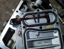
For preventive repair of a Bosch injection pump with your own hands, you will need to disassemble the pump in approximately the following order:
- remove the metering valve from the end of the injection pump. To do this, unscrew the four screws of the pressure plate, carefully release the cable of the injection advance valve. By removing the three screws securing the metering valve, you can carefully remove it from the seat;
- by unscrewing the fastener on the top cover, you can remove the control board and gain access to the electronics;
- we set the position of the shaft, as shown in the photo, remove the camera and get access to the insides of the injection pump;
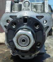
- after dismantling the bearing using a special puller, we get the opportunity to study the potential culprit for the poor performance of the injection pump - the piston of the injection advance unit. There is often surface wear and edge scuffing on the part. You can try to make repairs by polishing the surface, replacing the whole part is much more expensive.
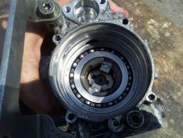
After the repair, the assembly is carried out in the reverse order with the washing of the parts with diesel fuel.
Often, in addition to scoring, on the surface of the pistons there is another reason why the injection pump does not develop the required pressure. This can be due to debris, films or wax build-up on the filter screen inside the pump. There is a mesh on the side of the inlet pipe. Rinsing the channels is a troublesome and ineffective business, it is easier to remove the mesh and blow it with compressed air.
Torn pieces of debris can jam the plunger piston or even break or break the pump drive shaft. Therefore, cleaning should be done very carefully to avoid contamination of the internal cavities of the pump.
Among the many reasons for the failure of the electronic "liver" of the injection pump, the most common is the breakage or burnout of the contacts of the control board and the failure of power transistors. If the knowledge and skills of working with electronic devices allow to carry out a "continuity" of the transistor performance and repair, it is worth trying to identify the cause and replace the culprit with a serviceable element.
To check the condition of the "culprit", you need to carefully open the black cover, which is tightly seated on the rubber seal with screws. It should be removed carefully so as not to damage the seal itself.
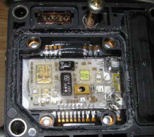
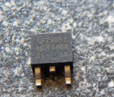
The reason for the failure of not only the transistor, but also the entire board could be air trapped in the cavity due to poor performance of the drainage system or the check valve. Often, they try to eliminate the airing by spinning up with a starter, hoping to pump diesel fuel into the high-pressure fuel pump in this way. At this moment, the transistor is open and loaded as much as possible, which leads to intense heating. In an air environment with poor heat dissipation, it will inevitably burn out. In some German cars there is a protection that prevents an attempt to start the engine in the absence of fuel in the highway. For this, a fuel sensor in the tank is used.
Failure of the transistor can be established by "dialing" a tester or by its appearance. The best option for repairing such a malfunction would be to replace the entire control board. Perhaps it is more expensive than soldering, but it will give guaranteed quality and stable operation of the injection pump after repair. As a last resort, give the board and the transistor for soldering to electronics specialists.
When installing and reassembling after repairs, check the tightness of all fasteners.
If during the audit you did not make rash and unreasonable replacements of parts, the assembled pump should work with approximately the same parameters as before. Bosch EPS-815 stand is used as a standard for testing and adjusting injection pump after overhaul.
The video shows how to raise the plunger pressure in a Bosch VE injection pump:
You know what fuel in Russia, you need to clean the nets in the fuel pump, and how many of them and where and how to get don’t, I don’t know.
and one more trouble - the engine is running low speed 650
warms up more than 850
on the tolmouth I read it should be the other way around, initially large, and with warming up, some kind of engine warming up device will decrease there
is it possible to customize it at home - if it is not difficult to explain what and how in detail.
if there are photos, it will be clear and clear what and where, but it's so scary to climb
well, about the rest of the sores next time
and so I do not regret that I bought a diesel-it is trouble-free, reliable, strong = it's absolutely super
catching up with the number
1 what this bolt regulates
2 bolt on it, the spring is
3 what kind of electronic unit
the car is not started - normally it does not drip
as soon as you start it, it starts to drip on a cold one
it will warm up for 5-10 minutes all the way does not drip it is not scary
and how to fight with it or inappropriately
how to check the speed increase valve when the stove is turned on
I turn on the stove does not add
I found him, but I don’t know what to do
Added by (10 Feb 2010, 08:09)
———————————————
I am writing a full report on the work done with your help
started the engine, adjusted the speed with the bolt
engine is warming up rpm does not drop
began to study the structure of what and how interacts
the heating valve comes out with increasing temperature
but the turnover does not fall, it turned out that
by the way, drops of antifreeze drip from it a little 15 - 20
it turned out that
Vacuum actuator for increasing the speed of XX in connection with the inclusion of the refrigerator, air conditioner or button for increasing the speed of XX.
is involved in this system and with its hook does not allow the bar to move away
increased the stroke on it until it began to interfere with work
the heating valve and everything with the hoist as it should work
tell me what rpm should be on the engine
1 heated
2 cold
I have automatic transmission
it seems there are differences with the mechanics
about the nets, you wrote that the Japanese are all the same fuel injection pump
but this is the first time I see the fuel pump and I don't know where other nets are
but I'm afraid to climb in the wrong place if you can show it in the photo
I changed the fuel filter to a fuel pump and blow it out and it would be good
thanks again without you I would be lost
on other forums was engaged in verbiage of no sense
but here everything is clear at once you can see the specialist
if what manuals on machines in electronic form are needed, write off what I scanned from what I dug on the Internet
I opened the flushing liquid right here
and in stores they sell pouring directly into fuel
as if it washes the pump. injectors. the valves say
that after it the engine works better, it should be applied every 5000t km
do not you know you can use this?
Attention, the editors of the site "Your Road" recommend that you consult with a specialist before applying this instruction to action.
One of the most mysterious parts of a car with a diesel engine is a high-pressure fuel pump (TNVD). There are 2 types of pumps - a mechanical pump and an electronically controlled pump, popularly EFI-shny. Each of the types is divided into 2 subspecies: Multi-plunger in-line, single-plunger distribution type (VE). We will not consider the "exotic" type of pump-injector, Common Rail or VR series distribution pumps (Distribution pump with axial plunger, Distribution rotary injection pump)
Since the device, and therefore the principle of its operation, is a mystery for many, there is an opinion that specialized equipment and a specially trained person are needed to repair it. However, such a "gentleman's" set is not always at hand, so let's try to disassemble and assemble this tricky knot "on the knee". The object for preparation will be a high-pressure fuel pump, assembled in ancient times from several different-sized pumps, without using stands, but at the same time successfully spinning a 4D56 diesel engine WITHOUT TURBINE up to 8000 rpm. Externally, it can differ from the high-pressure fuel pump installed on your car only in the absence of a pressure corrector (a kind of mushroom-hat on the top cover) and some attachments. This does not change the essence of the matter.
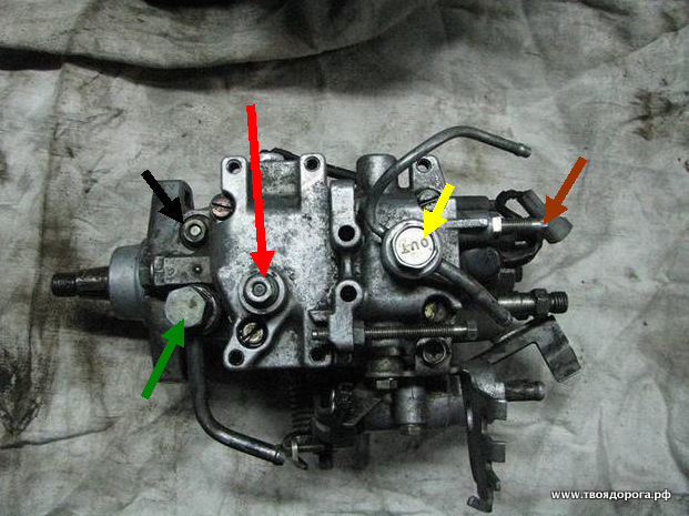
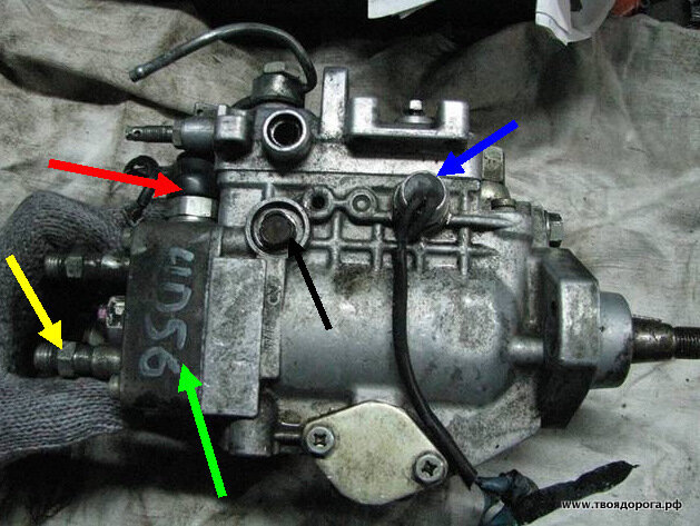
So, on the table- OH .. Top view
Colored arrows indicate:
- Green - fuel supply bolt
- Yellow - "return"
- Black - pressure valve in the injection pump housing
- Red - the axis of the fuel supply regulator ("gas" drive). The "gas" lever itself has been dismantled for convenience.
- Brown - mixture "quality" bolt.
Arrows indicate:
- Black - automatic heating
- Green - drive of the automatic heating device
- Red - automatic ignition timing (injection)
- Blue - identification plate
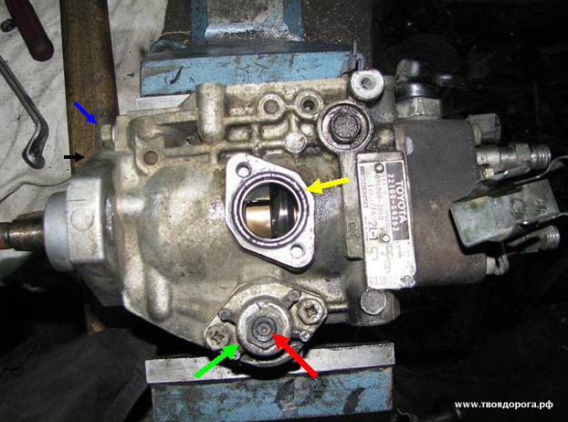
Side view (back side):
- Blue - speed sensor (tachometer, not always present)
- Red - fuel cut-off valve (muffler)
- Yellow - pressure valve.
- Green is the plunger itself.
- Black - the axis of the fuel lever. The same is available on the back of the pump. It is better to remove (but not completely unscrew) them at the initial stage of disassembly.
For work you will need: a set of heads, a set of hexagons, tweezers, screwdrivers, a gas wrench, a caliper, a vice, a clean rag, a container with clean diesel fuel, a grease (Litol, CV joint, etc.) -))
- A mesh filter is installed inside, which, as a rule, cannot be washed. Removal has no “contraindications” (yellow arrow).
- Has a calibrated hole on the side surface (red arrow). Different pumps have different sizes, so replacing them with another leads to a change in the internal pressure in the pump.
I think no comments are needed. Council - the drive itself should not be disassembled.
- Yellow - speed sensor
- Green - "jammer".
- Black - centrifugal speed controller.
- Blue - fuel drive lever.
Here one difficulty is to get to one of the 3 bolts. There are only two options:
Disassemble the drive (carefully, there is a powerful spring! + REMEMBER the setting of the adjusting bolt), and then calmly unscrew the rest.
Unscrew 2 "light" bolts under the key "by 10", loosen the third, "heavy" one, and pushing the assembly aside, slowly unscrew it.
It should look like this:
- Yellow - O-ring
- Red- adjusting bolt of the automatic advance switch
- Green - the cover of the advancing machine.
- Remember (write down) the bolt head protrusion (red arrow) above the cover (green arrow). If in the process you decide to unscrew this bolt, during assembly it will be necessary to return the dimensions to their original state.
- Blue - the axis of the speed regulator.
- Black - mating plane.
Attention! For pumps with RIGHT rotation, the thread on the shaft will be LEFT and vice versa!
If you can find a tool, unscrew the pressure regulator.
Now the fun begins. Parsing includes nodes consisting of several parts. Moreover, the details cannot "live" without each other. That is, they simply cannot be confused with each other.
- Red - pressure valve body
- Green - spring returnable
- Blue - valve needle
- Yellow - valve seat
- Black - sealing washer.
The plug under the red arrow does not need to be unscrewed; it serves to install the indicator. The fact is that the ignition on diesels is placed not so much on the marks. Rather, initially, the moment of injection is set according to the indicator, and only then the mark that we see is applied. We will omit this procedure for now, the turn will come to it.
So, turn off the cap (blue arrow). This is where the gas wrench comes in handy. The thread of the plug is right-hand.
- Blue - plunger body
- Red - plunger.
At this stage, it is necessary to measure the amount by which the plunger sinks into the body. We measure the results, write them down, they will come in handy during assembly.
We release the fastening screws (but not completely), and gently shaking, we move the plunger body up. As soon as it is free, we finally unscrew the screws and remove the plunger body. You should get the following picture:
- Blue - plunger
- Yellow - dosing ring
- Red - washer - bearing
- Brown - base plate
- Black - spring
- Green - adjusting washers.
- Black - Plunger Shim
- Red - cam washer.
- Green - fuel delivery lever. I managed to take it off earlier.
Attention!! We do not remove the videos, we do not change them in places.
Remove the stopper (shown with a screwdriver).
We see a pin under the stopper. Shown also with a screwdriver (it is magnetized, the pin can be easily removed by it).
Remove the cam washer drive.
In the interior of the vacated space, push the axis of the advancing automaton:
For convenience, I deleted 1 video, there is nothing criminal here. Pull the roller ring outward for the axis of the advancing automaton. Caution, do not use unnecessary effort! At the slightest misalignment, the ring wedges in the body. Attempts to pull it out "insolently" will end in disrepair - the pump casing will be scrapped.
It should look something like this:
For the 2 "horns" sticking out in the depths of the pump, we take out the pump shaft with the gear of the regulator:
We return to the "remains" of the pump:
We release the bolts (blue arrows) and take out the booster pump cover (red arrow).
We turn over the pump housing.
We remove the oil seal (shown with a screwdriver).Warning - don't try to save it, it won't work anyway.
As a result, a bare body with a bushing pressed into it should remain. Like this:
High pressure fuel pump in the diesel power system. Violations in the operation of the device, their external manifestations. How can you repair the pump on your own, the sequence of actions. Tips for using specialized services.
Any diesel engine may sooner or later require repair of the high pressure fuel pump. As the human heart begins to "junk" over the years, so this apparatus is subject to age-related changes. Along with the natural wear and tear of parts, refueling with low-quality fuel also affects. Diesel units are more sensitive in this regard than gasoline engines.
The proposed article will help the owners of diesel cars in case of problems with the fuel pump. It also provides tips on how to repair this unit yourself.
The high-pressure fuel pump (TNVD) is an independent unit of the power supply system for internal combustion engines (ICE), primarily diesel. Although this device is also used on petrol injection engines, it was first used on a diesel engine.
Its main function is to create a pressure difference between the pressure line and the compression chamber in order to ensure reliable injection of fuel into the cylinder cavity. But this is not enough.
The pump also sets the sequence for supplying fuel to the working injectors, that is, it performs a distribution function. In addition, it regulates the flow rate depending on the driving mode (crankshaft speed) and on some other factors: engine temperature, turning the air conditioner on and off.
Finally, just as the ignition timing is adjusted in carburetor engines, the injection pump on a diesel engine automatically adjusts the injection timing.
There are three main types of pumps: in-line, multipoint injection and mainline. Their device is considered in a separate article. It is worth mentioning here only that in-line pumps were used until recently on diesel trucks, tractors and specialized road transport equipment.
Switchgears are installed on all light diesel cars and some trucks. Trunk lines are used in modern Common Rail fuel systems. Such pumps are deprived of the function of fuel distribution; this task is performed by the electronic engine control unit (ECU), which, according to the program, commands the working injectors.
What are the signs of a malfunction of the fuel pump? As mentioned at the beginning of the article, the main reasons for the loss of performance of the high pressure fuel pump are wear of rubbing surfaces and low quality of fuel. Here you can clarify that the low quality of diesel fuel should also mean the ingress of water into the fuel. The following are the external symptoms of a malfunctioning fuel pump:
- It is difficult to start the engine - most likely, the plunger pair (or steam) is worn out, and the pump does not develop the required pressure. It is checked in a simple way. You need to put a rag on the injection pump, pour cold water over it and wait a few minutes. Then try again. If the engine starts, then the reason is really wear. During cooling, the gaps in the interface decrease and the viscosity of the fuel increases, as a result of which the pump provides the required pressure.
- Loss of power. Due to the increased clearances, the injection pressure decreases, and the operation of the all-mode speed controller deteriorates.
- Overheating of the engine. The reasons may be incorrect operation of the automatic injection advance. In this case, it is impossible to postpone the repair of the injection pump "for later".
- The growing "appetite" of the power unit. Caused by fuel leaks, worn plunger couplings, incorrect injection timing.
- Hard work of the engine, which may be the result of too early injection moment and uneven supply of diesel fuel to different cylinders. True, the latter is practically impossible on distribution injection pumps, so, most likely, the matter is in the nozzles.
- Black exhaust from the exhaust pipe. The reason may be too late a fuel injection angle.
If you have any of the above symptoms, consider repairing your fuel pump. Below is considered how to fix some malfunctions of the axial injection pump of the distribution type with your own hands.
It should be noted that before taking on this work, you should study the device of the unit being repaired, find out what tools you may need, because in some cases you cannot do without special equipment, a puller, for example.
You should also prepare a camera to record each stage of disassembly. Otherwise, you can forget where these or those parts were. For disassembly, you need to prepare a suitable table and cover it with a clean cloth or at least a sheet of white paper. There should be no debris on the floor, otherwise an accidentally dropped part may not be found.
So, what can a non-qualified motorist do on his own?
- eliminate fuel leakage from the pump housing;
- check the serviceability of the solenoid valve;
- check the plunger fuel supply mechanism;
- check the automatic speed controller;
- clean filter nets;
- check the pressure developed by the device;
- adjust the automatic injection advance.
The sequence of actions for self-repair of a high-pressure fuel pump is described below. With the engine running, disconnect the rod connecting the gas pedal with the lever that regulates the fuel supply. Then manually swing the lever in the radial direction, trying to stretch the return spring.
If no diesel oil seeps through the annular gap, then the seal is not worn out. Otherwise, refurbishment of the pairing is required.
While the pump has not yet been removed from the engine, make sure that the fuel shut-off solenoid valve is in good working order. If the engine starts and stops when the key is turned, the valve is working properly. How to deal with a situation when this component fails during movement will be described below.
Now it remains to proceed to disassembling the pump. Before disconnecting the fuel lines and electrical supply from the unit, wipe its body and connections with a cloth soaked in diesel fuel, and then wipe it dry to prevent dirt from entering the fuel system. Rinse the removed pump again, then remove the cover and drain the fuel from it.
First of all, you need to disassemble the drive for adjusting the fuel supply and revise the seals, as well as assess the degree of wear of the mating parts. O-rings must be changed. For this purpose, you need to buy a repair kit for the device being repaired.
As for worn parts, there are two ways to restore them: restore the worn axle using chrome plating, or grind and put a repair bronze bushing in the body. The body will have to be bored before this.
Next, you should proceed to disassembling and revising the plunger supercharger. Disconnect the pump distributor head from the housing, and then put it with a pulley downward so that the insides do not spill out. Before removing the cams, the drive gear and the centrifugal regulator clutch, you need to check if these parts are jammed during movement, and then, gently supporting them with your fingers, remove them from the housing.
It is advisable to mark the rollers, washers, axles of the cam clutch with a marker, because all the mating surfaces have already rubbed into each other, and it will be better if they remain after assembly.After disassembly, you need to carefully inspect the parts for chipping or depletion. Replace badly worn elements with new ones.
The wear rate of the plunger pair can only be estimated approximately. The performance of the precision mate is verified after the pump is assembled by measuring its operating pressure. Finally, you need to blow through all filter elements (nets) with compressed air, after which you can assemble the pump in reverse order.
When the unit is assembled, you need to fill it with diesel fuel by turning the drive roller by hand, after which you can put in place and connect the fuel lines, hoses and wiring of the control system.
After the engine is started, you should make sure that the fuel injection advance automat is working correctly, depending on the pressure in the cavity of the low-pressure vane pump. This block has its own idle speed regulator. If necessary, adjust this parameter by tightening or unscrewing the adjusting screw.
Before performing this procedure, it is recommended to memorize the position of the screw, counting the number of threads protruding from the locknut, in order to, in extreme cases, return to the original setting. The engine manual indicates the required number of revolutions at idle of the engine. Usually they decrease from 1100 rpm after starting to 750 - after warming up a diesel engine with a manual transmission, and to 850 - on an engine with an automatic transmission.
In conclusion, the pressure in the pressure line is checked, which is an indirect check of the condition of the plunger pair. For this purpose, you need a pressure gauge designed for pressures up to 350 bar, a connecting hose for connection to the pump and an adapter that includes a bleed valve.
As a measuring device, a TAD-01A manometer or an older one - KI-4802 is suitable. If the adapter is not available on sale, you will have to make it yourself.
Of course, it is necessary to take into account the dimensions of the connecting thread, and where it is planned to screw the connecting hose. For measurement, the device is connected to the central opening of the distribution block or to one of the pressure connections.
After connecting the pressure gauge to the high pressure fuel pump, turn the pump shaft with a starter and record the dial gauge. If the device shows more than 250 atmospheres, this is normal (with the engine running, the pressure will be higher).
As promised above, a few words about what to do if the fuel shut-off solenoid valve fails along the way. In this case, the engine will suddenly stop. True, there may be several reasons for this. To reject the version of the malfunction of the solenoid valve, it must be excluded from operation, since in normal mode it is always open.
To do this, you need to remove the supply wire, isolate it from the ground, then unscrew the valve, remove the tip with the spring from it and put the device back. If the engine still does not start, the reason is obviously something else. If the engine starts, you need to look for a malfunction in the valve.
To do this off the road, you must first get home. True, you will have to turn off the engine roughly, but simply: put the car on the handbrake, turn on an overdrive and release the clutch pedal.
And then start the repair. First, you should check if the solenoid winding is burnt out. To do this, connect the valve to the battery plus using a piece of good wire, and then try to start the engine. If it starts, then the winding has burned out. Otherwise, look for the place of voltage leakage from the lead wire.
Those who do not have the desire or ability to repair the injection pump on their own should contact a specialized fuel equipment repair station.Although there are dealerships that service and repair cars of a certain brand, they, as a rule, do not deal with fuel equipment, since this requires expensive diagnostic equipment.
The main stand for diagnostics and adjustment of the high pressure fuel pump is Bosch EPS-815. It checks various parameters set for a given pump by the manufacturer. For example: starting fuel supply, volumetric supply in various modes, outlet pressure and some others.
When choosing a service, you should consider its reliability. To do this, you must first arrive for an interview, where you can ask the opinion of the clients served. In such cases, pay attention to the history of the selected service. As a rule, unscrupulous firms exist in the service sector for no more than one year.
The weak link of the injection pump of diesel engines is their sensitivity to water entering the fuel system. Passenger cars, for which water is the main enemy, are especially susceptible to this. To mitigate this danger in winter, keep the fuel level in the tank as high as possible in order to minimize the formation of condensation.
| Video (click to play). |

