In detail: do-it-yourself repair of fuel pump yamz 238 from a real master for the site my.housecope.com.
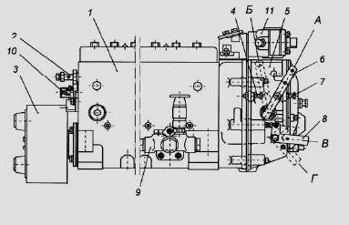
The fuel pump of the injection pump of the YaMZ-238 diesel engine of MAZ-5516, MAZ-64229, 6303 and Kraz-255, 6510, Kraz-65101 vehicles is shown in Fig. 14.
Rice. 14. TNVD YAMZ-238
1 - high pressure fuel pump; 2 - bypass valve; 3 - damper clutch; 4 - bolt for limiting the maximum speed; 5 - speed regulator; 6 - regulator control lever; 7 - bolt for limiting the minimum speed; 8 - stop bracket; 9 - fuel pump; 10 - bolt for adjusting the starting feed; 11 - corrector for boosting fuel supply.
A - the position of the lever at the minimum idle speed; B - position of the lever at maximum idle speed; B - the position of the bracket during operation; G - the position of the staple when the feed is off
With the YaMZ-238 injection pump, a rotational speed regulator 5, a fuel pump 9 and a damper clutch 3 are combined in one unit.
Diesel injection pump device YaMZ-238
The high-pressure fuel pump of the YaMZ-238 injection pump for MAZ-5516, MAZ-64229, 6303 and Kraz-255, 6510, Kraz-65101 vehicles consists of sections, individual pumping elements located in a common housing.
The number of sections is equal to the number of engine cylinders.
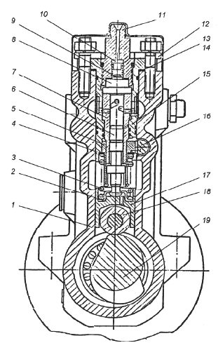
The structure of the YaMZ-238 injection pump section is shown in Fig. 15.
Rice. 15. Section of the high pressure fuel pump YaMZ-238
1 - pump casing; 2 - lower plate of the pusher; 3 - pusher spring; 4 - the upper plate of the pusher; 5 - swivel sleeve; 6 - plunger; 7 - plunger sleeve; 8 - discharge valve seat; 9 - discharge valve; 10 - valve stop; 11 - fitting; 12 - pressure flange; 13.14 - gaskets; 15 - section body; 16 - rail; 17 - pusher; 18 - pusher roller; 19 - cam shaft
| Video (click to play). |
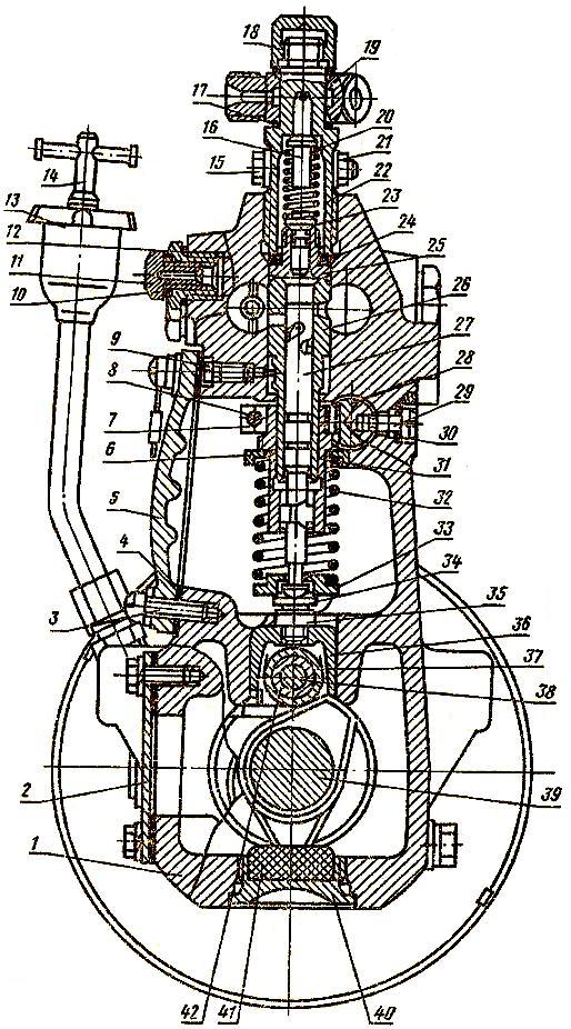
In the body 1 of the pump, the bodies of sections 15 are installed with plunger pairs, discharge valves and fittings 11, to which high pressure fuel lines are connected.
Discharge valve 9 and valve seat 8, as well as plunger 6 with sleeve 7 are precision pairs that can only be replaced as a complete set.
The plunger sleeve is locked in a certain position by a pin pressed into the section body.
The plunger 6 is driven from the camshaft 19 through the roller follower 17.
Spring 3 through the lower plate 2 constantly presses the pusher roller to the cam
From turning, the pushers, which have flats on the side surfaces, are held by clamps pressed into the pump housing of the YaMZ-238 injection pump.
The design of the plunger pair allows metering of fuel by changing the moment of the beginning and end of the supply.
To change the amount and moment of the beginning of the fuel supply, the plunger in the bushing is turned by the rotary bushing 5 (Fig. 2), which engages with the rack 16.
Adjustment of the uniformity of the fuel supply at maximum mode by each section of the injection pump of the YaMZ-238 diesel engine of MAZ-5516, MAZ-64229, 6303 and Kraz-255, 6510, Kraz-65101 vehicles is performed by turning the section body with loosened section fastening nuts.
The change in the geometric start of the discharge depending on the amount of feed (engine load) is provided by control edges made at the end of the plunger.
The principle of operation of the injection pump section of the YaMZ-238 diesel engine
When the plunger 6 moves downward under the action of the spring 3, the fuel under a small pressure generated by the fuel priming pump enters through the longitudinal channel in the housing into the space above the plunger.
When the plunger moves upwards, the fuel through the discharge valve enters the high-pressure fuel line of the YaMZ-238 diesel engine and is bypassed into the fuel supply channel until the end edge of the plunger covers the inlet of the bushing.
With further upward movement of the plunger, the pressure in the space above the plunger increases sharply.
When the pressure reaches such a value that it exceeds the force created by the injector spring, the injector needle will rise and the process of injecting fuel into the engine cylinder will begin.
With further movement of the YaMZ-238 high pressure fuel pump plunger upward, the cut-off edges of the plunger open the cut-off holes in the bushing, which causes a sharp drop in fuel pressure in the discharge line, the nozzle needle landing on the closing cone of the sprayer and cessation of the fuel supply to the combustion chamber.
On the inner surface of the plunger sleeve 7, there is an annular groove, and in the wall there is a hole for withdrawing fuel that has leaked through the gap in the plunger pair.
The seal between the plunger sleeve and the section casing, the section casing and the pump casing is carried out by rubber rings.
From the cavity around the plunger sleeve, leaked fuel flows through the groove on the plunger sleeve into the low pressure cavity of the pump housing and then through the bypass valve and pipeline into the fuel tank.
A camshaft is located in the lower part of the fuel pump body of the YaMZ-238 injection pump for MAZ-5516, MAZ-64229, 6303 and Kraz-255, 6510, Kraz-65101 vehicles.
The camshaft rotates in tapered roller bearings and an intermediate bearing.
The camshaft is installed with an interference fit of 0.01 - 0.07 mm, which is provided by adjusting and spacers installed between the bearing cover and the pump housing.
The connection of the sections with the pump speed regulator of the YaMZ-238 injection pump is carried out through the rail.
The rail of the YaMZ-238 injection pump moves in guide bushings pressed into the pump casing.
At the end of the rail protruding from the pump, there is a bolt 10 (Fig. 1), with which it abuts against the protective cap when the rail is positioned before starting the engine.
When unscrewing the bolt from the rail, the starting feed decreases.
Lubrication of the injection pump YaMZ-238 - centralized, from the engine oil system.
Oil is supplied to the boost corrector, from where, merging into the regulator cavity, it enters the pump camshaft cavity.
Regulator of frequency of rotation of injection pump of diesel engine YaMZ-238
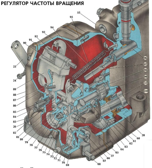
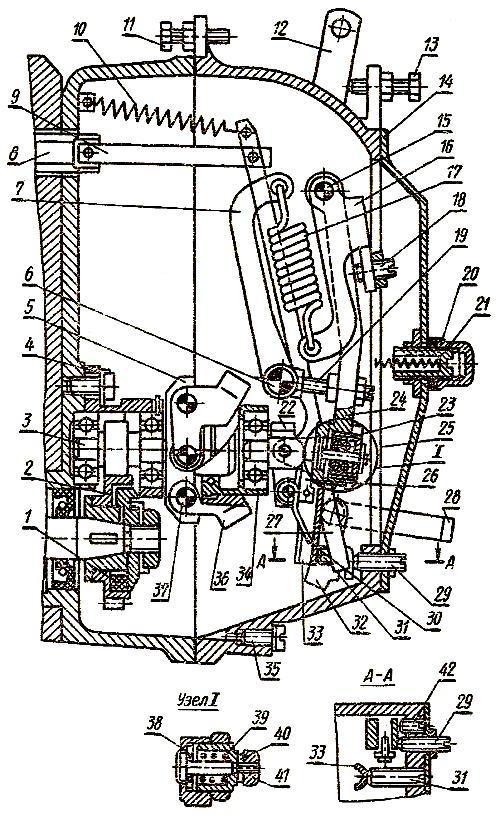
The speed regulator of the injection pump YaMZ-238 for MAZ-5516, MAZ-64229, 6303 and Kraz-255, 6510, Kraz-65101 vehicles (Fig. 16) mechanical all-mode direct action with an overdrive to drive loads, designed to maintain the speed set by the driver engine operation by automatically changing the amount of supplied fuel depending on changes in engine load.
Rice. 16. Regulator of frequency of rotation of injection pump of the YaMZ-238 engine
1 - corrector for boosting fuel supply; 2 - the axis of the two-armed lever; 3 - inspection hatch cover; 4 - regulator spring; 5 - two-armed lever; 6 - the spring of the rack lever; 7 - two-arm lever screw; 8 - buffer spring; 9 - buffer spring housing; 10 - an adjusting bolt; 11 - spring lever shaft; 12 - negative corrector; 13 - body of the corrector spring; 14 - spring of the negative corrector; 15 - backstage bracket; 16 - bushing of the negative corrector; 17 - regulator lever; 18 - negative corrector lever; 19 - power adjustment screw; 20 - rack lever; 21 - curtain; 22 - heel; 23 - cargo clutch; 24 - weights of the regulator; 25 - weight holder; 26 - axis of loads; 27 - driving gear; 28 - crackers; 29 - load holder roller; 30 - glass; 31 - spring lever 32 - rack rod; 33 - rail; 34 - emphasis
In addition, the YaMZ-238 injection pump regulator limits the maximum engine speed and ensures that the engine operates in idle mode.
The YaMZ-238 injection pump regulator has a device for turning off the fuel supply at any time, regardless of the engine operating mode.
By automatically maintaining the speed at varying loads, the regulator ensures economical operation of the engine.
Working adjustments of injection pump YAMZ-238
The minimum idle speed is adjusted by bolt 7 (Fig. 1) and the buffer spring housing 9 (Fig. 16);
The maximum idle speed (the beginning of the ejection of the rack) is regulated by bolt 4 (Fig. 14).
Rated power (feed) is regulated by bolt 10, adjusted by screw 19 (Fig. 16).
The pre-tension of the spring (the difference between the turns of the end and the beginning of the ejection of the rack) is adjusted by screw 7.
The fuel supply at 500 rpm is regulated by the reverse corrector nut 12.
The preliminary tension of the reverse corrector spring (revolutions of the beginning of the corrector operation) is regulated by the corrector body 13 (Fig. 16).
The peculiarities of adjusting the YaMZ-238 injection pump for MAZ-5516, MAZ-64229, 6303 and Kraz-255, 6510, Kraz-65101 vehicles should include the fact that in order to ensure a reduced force on the control lever, the spring lever when adjusting the speed of rotation of the start of the regulator should be as close as possible to the stop in the regulator body, limiting its rotation.
Readjust the beginning of the regulator action with the screw of the two-arm lever.
Damper clutch for injection pump YAMZ-238
The high-pressure fuel pump of the YaMZ-238 injection pump is equipped with a damper clutch, which is installed on the conical surface of the front end of the camshaft with an interference fit created by an annular nut and is secured against turning with a key.
The damper clutch of the YaMZ-238 injection pump is designed to protect mechanisms from destruction.
The damper clutch of the YaMZ-238 injection pump is a non-separable design with a freely rotating flywheel in a special high-viscosity liquid.
Dents on the clutch housing damage the clutch.
A reliable fuel pump is installed in MAZ, MTZ diesel engines and other brands of cars.
The unit is part of the engine's injection system.
It has a complex design. Also TNVD YAMZ:
- Defines the start of the injection;
- Performs a gradual injection of fuel.
Today, injection pumps YAMZ 238, 236 are especially popular.
The parts are almost identical in structure.
The main stages of the fuel pump:
- Fuel is pumped through the fitting. The part is connected to the reduced pressure pipe.
- The small camshaft as well as the spring starts to move. Therefore, the piston moves up and down;
- The cam shaft starts to work.
It is located at the bottom of the YaMZ 238 injection pump. The part rotates in a support and bearings.
The robust travel regulator communicates with the sections of the unit through a rack, which also rotates in several bushings.
The start is reduced by progressively unscrewing the corresponding bolt from the rail.
The lubricant and its scheme of the YaMZ 238 injection pump is as follows: the central type from the engine oil system. Oil is supplied only by pressurization to the surface of the corrector.
From this point it moves to the regulator, and then to the camshaft of the pump.
In this figure, you can carefully consider the diagram of the YaMZ 238 injection pump.
The main elements of the system:
- TN housing;
- Valve;
- Bolt (used to limit maximum rotation);
- Regulator and coupling;
- Bolt (used to limit minimum rotation);
- Brace as well as lever;
- Fuel pump;
- Bolt (used to adjust the starting feed);
- Boost fuel corrector.
The device of the YaMZ 238 injection pump includes special sections (their number is equal to the number of cylinders).
The device of the plunger pair is modeled in such a way that the fuel dosage is carried out by adjusting the feed moments.
Therefore, the basic design of the YaMZ injection pump includes:
- Plunger and bushing. It is these elements that are connected to a plunger pair. Remember to keep the clearance between parts as small as possible.
- As soon as the piston moves inside the cylinder, a rapid fuel injection occurs.
The YaMZ 238 injection pump circuit cannot function without a sleeve and, of course, a plunger.
If parts fail, the engine's high pressure fuel pump will break.
Therefore, for effective operation, it is necessary to monitor the minimum distance between the elements, to adjust the YaMZ 238 injection pump.
Malfunctions of the fuel pump can also be associated with the accumulation of dirt, seizure of the part.
In this case, we advise you to inspect the YaMZ injection pump device and, if necessary, clean it.
Re-adjust the sleeve and plug if necessary.
For more information on how to repair the YaMZ injection pump, adjust the unit, read the following articles of our blog.
Do not forget that you can always buy YaMZ injection pump in our catalog.
The device of the fuel pump TNVD diesel engine YaMZ-238
The high-pressure fuel pump of the YaMZ-238 injection pump for MAZ-5516, MAZ-64229, 6303 and Kraz-255, 6510, Kraz-65101 vehicles consists of sections, individual pumping elements located in a common housing.
The number of sections is equal to the number of engine cylinders.
1-Cap nut; 2-Washer; 3-Nipple; 4-Nut; 5-Washer; 6-Crack; 7-Schutzer; 8-Fitting; 9-Valve stop; 10-Spring; 11-Gasket; 12- Blower valve ; 13-Bypass valve assembly; 14-Plug; 15-Washer; 16-Adjusting washer; 17-Spring; 18-Valve guide; 19-Ball B 6,35 mm; 20-Valve body; 21-Screw; 23- Power limiter bushing; 24-Power limiter screw; 25-O-ring; 26-Screw; 27-Screw; 28-Washer; 29-Washer; 30-Locking screw; 31-Stopper; 32-Bolt; 33-O-ring; 34 - A pair of plunger; 35-Screw;
36-Washer; 37-Rack; 38-Fuel pump housing; 39-Washer; 40-Plug; 42-Air release plug; 43-Screw; 44-Key; 45-Toothed rim with sleeve; 46-Toothed rim; 47- Ring bushing; 48-Upper plate; 49-Pusher spring; 50-Lower plate; 51-Plunger pusher; 52-Camshaft support; 53-Bolt; 54-Cotter pin-wire; 55-Sealing ring; 56-Cam shaft; 57-Cover gasket; 58-Cover; 59-Screw; 60-Washer; 61-Screw; 62-Plug; 63-Washer; 64-Roller bearing; 65-O-ring; 66-Indicator of the beginning of fuel supply; 67-Gasket; 68-Gasket; 69-Bearing cover; 70-Screw; 71-Cuff
With the YAMZ-238 injection pump, a speed regulator, a fuel pump and a damper clutch are combined in one unit.
Pump speed regulator for injection pump YaMZ-238
The rotational speed regulator is a mechanical all-mode direct action with an overdrive to drive loads, designed to maintain the engine speed set by the driver by automatically changing the amount of fuel supplied depending on the change in engine load. In addition, the governor limits the maximum engine speed and keeps the engine idling. The regulator has a device for turning off the fuel supply at any time, regardless of the engine operating mode. By automatically maintaining the speed at varying loads, the regulator ensures economical operation of the engine.
The regulator is located at the rear end of the high pressure fuel pump. On the cone of the camshaft there is a drive gear with a damping device. Rotation from the pump shaft to the drive gear is transmitted through rubber rusks. The driven gear is made as one piece with the weight holder roller and is mounted on two bearings in a glass.
1- cam shaft; 2- cargo holder; 3- spring lever; 4- rail; 5- spring; 6- rod thrust; 7- regulator spring; 8- double-armed lever; 9- hatch cover; 10- rack lever; 11- regulator lever; 12- buffer spring; 12- buffer spring; 13- bolt of nominal feed; 14- proofreader; 15- backstage bracket; 16- curtain; 17 - heel of cargo; 18- cargo clutch; 19- cargo; 20- elastic coupling; 21 - gear; 22- control lever; 23- bolt of minimum speed; 24- bolt of maximum speed; 25 - roller; 26- swing axis.
Working adjustments of injection pump YAMZ-238
The minimum idle speed is adjusted by the bolt and the buffer spring housing;
The maximum idle speed (the beginning of the ejection of the rack) is regulated by a bolt.
The rated power (feed) is regulated by the bolt 10, it is adjusted by the screw.
The pre-tension of the spring (the difference between the turns of the end and the beginning of the ejection of the rack) is adjusted with a screw.
Fuel supply at 500 min-1 is regulated by the reverse corrector nut.
The preliminary tension of the reverse corrector spring (revolutions of the beginning of the corrector operation) is regulated by the corrector body.
The peculiarities of adjusting the YaMZ-238 injection pump for MAZ-5516, MAZ-64229, 6303 and Kraz-255, 6510, Kraz-65101 vehicles should include the fact that in order to ensure a reduced force on the control lever, the spring lever when adjusting the speed of rotation of the start of the regulator should be as close as possible to the stop in the regulator body, limiting its rotation.
Readjust the beginning of the regulator action with the screw of the two-arm lever.
Damper clutch for injection pump YAMZ-238
The high-pressure fuel pump of the YaMZ-238 injection pump is equipped with a damper clutch, which is installed on the conical surface of the front end of the camshaft with an interference fit created by an annular nut and is secured against turning with a key.
The damper clutch of the YaMZ-238 injection pump is designed to protect mechanisms from destruction.
The damper clutch of the YaMZ-238 injection pump is a non-separable design with a freely rotating flywheel in a special high-viscosity liquid.
Dents on the clutch housing damage the clutch.
Checking and adjusting the cyclic fuel supply and uniformity of the injection pump of the YaMZ-238NB and YaMZ-240B engines of the Kirovets K-700, K-700A, K-701, K-702 tractors
Ne should nTo override the factory setting of the speed regulator unnecessarily. All the adjustments described below are performed if the deviation of the cycle feed, as well as the speed from the nominal, exceeds 5%, or if a bulkhead or replacement of parts was carried out.
PProcedure for checking and adjusting the injection pump of the YaMZ-238NB and YaMZ-240B engines of the Kirovets K-700, K-700A, K-701, K-702 tractors:
1) - Checking the fuel pressure in the lines at the exit to the injection pump. If the pressure differs from the indicated one, unscrew the bypass valve and, by turning its seat, adjust the opening pressure. Raise the valve seat upon completion of the adjustment;
2) - Check the tightness of the discharge valves. When the rack is in the position that corresponds to the off supply, fuel under a pressure of about 1.7-2 kgf / cm 2 (170-2 kPa) should not be passed through the pressure valves for 2 minutes. If necessary, the valve is replaced;
3) - Checking the speed of the camshaft of the injection pump (corresponds to the beginning and end of the rack extension) when the control lever rests on the bolt for limiting the maximum crankshaft speed. If necessary, the frequency of rotation of the beginning of the extension of the rack is adjusted by means of bolt 11 [Fig. 1] limiting the maximum speed, and the end of the rack extension - using the screw (18) of the two-arm regulator lever;
Rice. 1. Regulator of frequency of rotation.
8) - Rack of the high pressure fuel pump;
11) - Bolt for limiting the maximum idle speed;
12) - Regulator control lever;
13) - Bolt for limiting the minimum idle speed;
18) - The screw of the two-armed lever;
20) - Side spring housing;
25) - Regulator corrector (engine YMZ-238NB);
29) - Power adjustment screw;
35) - Drain plug;
4) - The performance of the injection pump sections is checked when the control lever rests on the maximum speed limiting bolt. The average cycle delivery (total delivery by all sections of the fuel pump divided by the number of sections) should be 93 mm 3 / cycle. The adjustment is not carried out if the deviation of the average cycle feed does not exceed 2%, and the unevenness of the fuel supply by the sections is less than 8%. If the deviations are greater than those indicated above, the following adjustment is performed:
a) - Checking the power reserve of the rack (the power reserve should be 0.5 mm) in the direction of switching on the fuel supply when the regulator control lever rests on the bolt (13) for limiting the maximum speed and at 450-500 rpm of the camshaft of the injection pump. If necessary, the power reserve is adjusted by means of the slide screw (42);
b) - Adjustment of the feed of each section with the recessed corrector, the stop of the regulator control lever in the bolt (11) for limiting the maximum rotation frequency, as well as at 920-940 rpm of the camshaft. The feed is regulated by 88-90 mm 3 / cycle by displacement of the rotary sleeve (31) [fig. 2] in relation to the ring gear with preliminary loosening of the corresponding clamping screw. When the control lever rests on the bolt (11) [Fig.1] limiting the maximum speed and at 920-240 rpm of the camshaft by screwing in the housing (39) of the corrector, the feed is increased in sections to 92-94 mm 3 / cycle. Next, you need to close the corrector body. When the control lever rests on the bolt (11) for limiting the maximum speed and at 740-760 rpm of the camshaft, the fuel supply is checked and adjusted (if necessary), which at 920-240 rpm should exceed the supply by 6-8 mm 3 / cycle. Adjustment is made with the adjusting nut (41). Checking the shutdown of the fuel supply is performed by the speed controller, which is turned to the lower position by 45 degrees. must completely stop the fuel supply by all pump sections;
Rice. 2. Section of the high pressure fuel pump of the Kirovets tractor.
Adjustment of the high pressure fuel pump of the YaMZ-238PM and YaMZ-238FM engines
The power and economic indicators of the engine, as well as the reliability of its operation, to a greater extent depend on the thoroughness and quality of adjusting the parameters of the injection pump. Therefore, the adjustment must be carried out by qualified personnel and on special equipment intended for these purposes. It is recommended to regulate the injection pump at the stands Star-12 "," Minor-8 ", (VNR),
NTs-108 (Czechoslovakia) and others similar in design.
The pump must be adjusted with a set of proven injectors attached to the sections, the injectors must be installed on the engine in the order of their attachment to the pump sections.
When adjusting the fuel pump, first of all, the start of the fuel supply by the pump sections is controlled, and then the amount and uniformity of the fuel supply. The start of fuel delivery is controlled without an automatic injection advance clutch at the start of fuel movement in the momentoscope (Fig. 29). The beginning of the fuel supply in sections is determined by the angle of rotation of the pump camshaft when rotating it clockwise, when viewed from the drive side. The first section of a properly adjusted pump begins to supply fuel 37–38 0 before the axis of symmetry of the cam profile.
Rice. 29. Momentoscope device:
1 - glass tube; 2 - transition tube; 3 - a section of the high pressure fuel line; 4 - washer; 5 - union nut
To determine the axis of symmetry of the cam profile, it is necessary to fix on the dial the moment the fuel starts to move in the momentoscope when the camshaft is turned clockwise, turn the shaft clockwise
arrow by 90 ° and fix on the dial the moment the fuel starts moving in the momentoscope when the shaft is turned counterclockwise. The midpoint between the two fixed points defines the axis of symmetry of the cam profile.
If the angle at which the first section begins to supply fuel is conventionally taken as 0 °, then the remaining sections should start supplying fuel in the following order:
The inaccuracy of the interval between the start of fuel supply to any section of the pump relative to the first is not more than 0 ° 20 '. The start of the fuel supply is regulated by the pusher bolt 49 (see Fig. 22). When the bolt is unscrewed, the fuel starts to flow earlier, when screwing in - later. After adjustment, you must lock the adjusting bolt with nuts.
The amount and uniformity of fuel supply by the high-pressure pump sections are regulated together with a set of nozzles and high-pressure fuel lines 415 ± 3 mm long. The volume of the inner cavity of each high-pressure fuel line must be 1.3 ± 0.1 cm, it is determined by the fuel filling method.
The sequence of checking and adjusting the amount and uniformity of the feed is as follows (the rotational speed of the pump camshaft is indicated): check the fuel pressure in the line at the inlet to the high pressure pump. The pressure should be in the range of 0.5-1.0 kgf / cm2 at 1050 min ”1. If the pressure is higher or lower, unscrew the bypass valve and adjust the opening pressure by turning its seat. After adjustment, the valve seat is stamped;
when the control lever rests on the bolt of the minimum speed, check and, if necessary, adjust the frequency of full automatic shutdown of the feed by the regulator within the range of 275-325 min-1. When unscrewing bolt 1 (see Fig. 24) of the minimum speed and housing 41 of the buffer spring, the frequency decreases;
with the control lever resting on the maximum speed limiting bolt, check the pump camshaft rotation speed corresponding to the beginning of the rack ejection (the beginning of the rack movement towards the feed off side). The regulator should start throwing the rack at 1070 + 1 ° min-1. If necessary, adjust the frequency with the maximum speed limiting bolt;
with the control lever resting on the maximum speed limiting bolt, check the pump camshaft speed corresponding to the end of the rack ejection (complete shutdown of the feed). The end of the ejection of the staff should be at 1120-1150 min-1. In case of deviation from this value, unseal and remove the inspection hatch cover of the regulator. When removing the cover, make sure that the position of the adjusting screw remains unchanged. The frequency of rotation of the end of the ejection of the rack is regulated as follows:
by changing the position of screw 3 (see Fig. 24) of the two-arm lever, set the maximum speed limiting bolt to start the rack ejection at 1070+ 10 min- ';
check the frequency of rotation of the end of the ejection of the rack and, if necessary, readjust it. When screwing in the screw of the two-arm lever and setting the beginning of the ejection of the rack at 1070 +1.1 min
'The frequency of rotation of the end of the ejection of the rack decreases, when turning out it increases;
when the control lever rests on the maximum speed limiting bolt and 1030 + 10 min-1, check the performance of the pump sections. Fuel supply by each section of the pump when working with injectors that have an "H" atomizer and are adjusted to the pressure of the beginning of the needle lift
200 + 15 kgf / cm2, should be within 128-130 mm ’! for each plunger stroke (cycle) for YaMZ-238PM engines and 138-140 mm'1 per cycle for YaME-238FM engines. The fuel supply by each pump section is regulated by the displacement of the swivel sleeve relative to the gear rim, for which it is necessary to loosen the clamping screw of the corresponding gear sector. When the sleeve is turned to the left relative to the crown, the feed decreases, to the right, it increases. After adjustment, check that the tightening screws are secure;
check the value of the starting fuel supply, which should be within 220-250 mm'3 per cycle at 80 ± + 10 min-1. Readjustment with screw 31 (see Fig. 24) of the yoke only in the direction of increasing the fuel supply, after which the screw is counter-chased. After readjustment, check and, if necessary, adjust the performance of the pump sections with the nominal flow adjustment screw;
check that the fuel supply is turned off with the regulator clamp. When the bracket is turned to the lower position at 45e ”, the fuel supply by all pump sections must completely stop. If the feed does not turn off, then you should check the ease of movement and eliminate the possible jamming of the rack;
seal the high pressure fuel pump and regulator;
install the automatic clutch and tighten the nut of its fastening with the application of a torque of 10-12 kgf-m. The injection advance clutch retaining nut is tightened whenever the high pressure fuel pump is removed from the engine.
Installing the injection pump on the engine
When installing the fuel pump, the marks on the injection advance clutch and the leading half of the fuel pump drive must be located on one side.
After fixing the injection pump to the cylinder block, it is necessary to check the axial clearances between the ends of the cams of the driving half of the coupling and the end of the injection advance clutch, as well as the clearances between the cams of the advance clutch
to the right and rear end of the half-coupling. These clearances must be at least 0.3 mm for each of the four cams.The lack of end clearance in the fuel pump drive can lead to failure of the pump bearings and to seizure of the fuel injection advance clutch. It is necessary to adjust the end clearance by axial movement of the fuel pump drive coupling half along the shaft with a loose nut of the tie bolt. At the end of the adjustment, the nut is securely tightened and pinned, after which the fuel injection advance angle is set.
After starting the engine, the minimum crankshaft idle speed within 550–650 rpm must be adjusted as follows:
unscrew the housing 41 (see Fig. 24) of the buffer spring by 2-3 mm, loosening the lock nut;
with the minimum speed limiting bolt (the control lever must rest against this bolt), adjust the minimum speed until slight fluctuations in the engine crankshaft speed appear. When screwing in the bolt, the engine speed increases, when screwing out, it decreases;
Unscrew the buffer spring housing until the speed instability disappears. Do not screw in the buffer spring housing until its end is aligned with the end of the locknut. After adjustment, lock the minimum speed bolt and the buffer spring housing with nuts.
1. Install the driven coupling half (Fig. 1, 2) on the advance coupling (damper coupling) and fasten with bolts.
2. Turn the coupling so that the bosses of the driven coupling half are in a horizontal position, and the mark on the end of the coupling is in the area of the indicator.
3. Install the coupling half flange, complete with the driving coupling half and plate packs, onto the drive shaft, while the protrusion "a" on the coupling half flange must be on the left side when looking at the drive from the fan side.
4. Install the high-pressure fuel pump with advance clutch (damper clutch) assembly on the engine and fasten it with bolts. Before tightening the drive pinch bolt and after setting the injection advance angle, adjust the flatness of the plate packs by moving the half-coupling flange along the drive shaft. Install the fuel pump on the engine block in a vertical position, tighten the mounting bolts evenly, avoiding blockage of the pump. The final tightening torque of the pump mounting bolts is 30 ... 40 Nm (3 ... 4 kgf.m).
5. Connect the pump sections to the injectors with high pressure fuel lines in the order shown in fig. 3.
6. Adjust the fuel injection advance angle. We look at the article How to adjust the fuel injection of the YaMZ-238 diesel engine
7. Check the presence of oil in the housings of the high pressure fuel pump and regulator, if necessary, add oil to the level of the hole for the oil drain pipe.
8. Connect the oil inlet and outlet pipes and fuel lines.
After starting the engine, adjust the minimum idle speed of the crankshaft as follows:
1. After loosening the lock nut, unscrew the buffer spring housing by 2 - 3 mm.
2. Using the bolt for limiting the minimum speed (the control lever must rest against this bolt), adjust the minimum idle speed until slight fluctuations in the engine crankshaft speed appear. When screwing in the bolt, the engine speed increases, when screwing out, it decreases.
3. Screw in the buffer spring housing until the speed instability disappears. It is strictly forbidden to screw in the buffer spring housing until its end is aligned with the end of the locknut. After adjustment, lock the minimum speed bolt and the buffer spring housing with nuts.
The minimum idle speed can also be adjusted on a new engine during the initial period of its operation.
It is strictly forbidden to violate the factory setting of the maximum speed without further testing at the stand during operation.
Popular models of YaMZ 236, 238 engines are unpretentious in operation. Vehicles with YaMZ engines have excellent cross-country ability and traction characteristics. Cars with diesel engines of the Yaroslavl Motor Plant are easy to maintain and economical. However, during the operation of freight transport, malfunctions in the fuel system may occur.
SAS # 1 provides services for the adjustment and repair of the high pressure pump for YaMZ engines.
The total cost of work in each case is determined individually directly in the car service. In some cases, it is enough to carry out precise adjustment, while in others it is necessary to carry out complex manipulations with the replacement of worn parts. You should not try to save money, troubleshooting must be complete to ensure the continued operation of the pump.
Normal operation of the engine ensures reliable start-up, fuel economy. In a diesel engine, air and fuel enter the cylinder separately: first, air is supplied, then atomized fuel is injected into the cylinder through injectors under high pressure.
- increased fuel consumption and increased smoke when the engine is running;
- fuel leakage from the high-pressure fuel pump;
- obvious wear of parts of the fuel pump;
- slipping of the timing belt;
- it is difficult or not to supply fuel from the pump to the nozzle;
- the appearance of extraneous noise in the injection pump.
In order to prevent further problems with the stability of the entire fuel system, it is necessary to find the cause of the breakdown and eliminate it during it. Repairing the fuel system of a diesel engine includes diagnostics of the injection pump and injectors (including measuring the injection pressure). Testing, adjustment and diagnostics are performed at a special stand. Professional equipment allows you to repair YaMZ efficiently and in the shortest possible time.
The fuel pump of the injection pump of the YaMZ-238 diesel engine of MAZ-5516, MAZ-64229, 6303 and Kraz-255, 6510, Kraz-65101 vehicles is shown in Fig. 14.
Rice. 14. TNVD YAMZ-238
1 - high pressure fuel pump; 2 - bypass valve; 3 - damper clutch; 4 - bolt for limiting the maximum speed; 5 - speed regulator; 6 - regulator control lever; 7 - bolt for limiting the minimum speed; 8 - stop bracket; 9 - fuel pump; 10 - bolt for adjusting the starting feed; 11 - corrector for boosting fuel supply.
A - the position of the lever at the minimum idle speed; B - position of the lever at maximum idle speed; B - the position of the bracket during operation; G - the position of the staple when the feed is off
A speed regulator 5, a fuel pump 9 and a damper clutch 3 are combined with a fuel pump in one unit.
Diesel injection pump device YaMZ-238
The YaMZ-238 high-pressure fuel pump consists of sections, individual pumping elements located in a common housing.
The number of sections is equal to the number of engine cylinders.
The device of the injection pump section is shown in Fig. 15.
Rice. 15. Section of the high pressure fuel pump YaMZ-238
1 - pump casing; 2 - lower plate of the pusher; 3 - pusher spring; 4 - the upper plate of the pusher; 5 - swivel sleeve; 6 - plunger; 7 - plunger sleeve; 8 - discharge valve seat; 9 - discharge valve; 10 - valve stop; 11 - fitting; 12 - pressure flange; 13.14 - gaskets; 15 - section body; 16 - rail; 17 - pusher; 18 - pusher roller; 19 - cam shaft
In the body 1 of the pump, the bodies of sections 15 are installed with plunger pairs, discharge valves and fittings 11, to which high pressure fuel lines are connected.
Discharge valve 9 and valve seat 8, as well as plunger 6 with sleeve 7 are precision pairs that can only be replaced as a complete set.
The plunger sleeve is locked in a certain position by a pin pressed into the section body.
The plunger 6 is driven from the camshaft 19 through the roller follower 17.
Spring 3 through the lower plate 2 constantly presses the pusher roller to the cam
From turning, the pushers, which have flats on the lateral surfaces, are held by clamps pressed into the pump casing.
The design of the plunger pair allows metering of fuel by changing the moment of the beginning and end of the supply.
To change the amount and moment of the beginning of the fuel supply, the plunger in the bushing is turned by the rotary bushing 5 (Fig. 2), which engages with the rack 16.
Adjustment of the uniformity of the fuel supply at the maximum mode by each pump section is made by turning the section body with loosened section fastening nuts.
The change in the geometric start of the discharge depending on the amount of feed (engine load) is provided by control edges made at the end of the plunger.
The principle of operation of the injection pump section of the YaMZ-238 diesel engine
When the plunger 6 moves downward under the action of the spring 3, the fuel under a small pressure generated by the fuel priming pump enters through the longitudinal channel in the housing into the space above the plunger.
When the plunger moves upward, the fuel enters the high-pressure fuel line through the discharge valve and is bypassed into the fuel supply channel until the end edge of the plunger covers the inlet of the bushing.
With further upward movement of the plunger, the pressure in the space above the plunger increases sharply.
When the pressure reaches such a value that it exceeds the force created by the injector spring, the injector needle will rise and the process of injecting fuel into the engine cylinder will begin.
With further upward movement of the plunger, the cut-off edges of the plunger open the cut-off holes in the bushing, which causes a sharp drop in fuel pressure in the delivery line, the nozzle needle settles on the closing cone of the atomizer, and the fuel supply to the combustion chamber stops.
On the inner surface of the plunger sleeve 7, there is an annular groove, and in the wall there is a hole for withdrawing fuel that has leaked through the gap in the plunger pair.
The seal between the plunger sleeve and the section casing, the section casing and the pump casing is carried out by rubber rings.
From the cavity around the plunger sleeve, leaked fuel flows through the groove on the plunger sleeve into the low pressure cavity of the pump housing and then through the bypass valve and pipeline into the fuel tank.
A camshaft is located in the lower part of the YaMZ-238 injection pump housing.
The camshaft rotates in tapered roller bearings and an intermediate bearing.
The camshaft is installed with an interference fit of 0.01 - 0.07 mm, which is provided by adjusting and spacers installed between the bearing cover and the pump housing.
The connection of the sections with the pump speed controller is carried out through the rail.
The rack moves in guide bushings pressed into the pump housing.
At the end of the rail protruding from the pump, there is a bolt 10 (Fig. 1), with which it abuts against the protective cap when the rail is positioned before starting the engine.
When unscrewing the bolt from the rail, the starting feed decreases.
Pump lubrication is centralized from the engine oil system.
Oil is supplied to the boost corrector, from where, merging into the regulator cavity, it enters the pump camshaft cavity.
Regulator of frequency of rotation of injection pump of diesel engine YaMZ-238
The high-speed pump speed regulator (Fig. 16) is a mechanical all-mode direct action with an overdrive to drive loads, designed to maintain the engine speed set by the driver by automatically changing the amount of supplied fuel depending on changes in the engine load.
Rice. 16. Speed regulator of the fuel pump of the YaMZ-238 engine
1 - corrector for boosting fuel supply; 2 - the axis of the two-armed lever; 3 - inspection hatch cover; 4 - regulator spring; 5 - two-armed lever; 6 - the spring of the rack lever; 7 - two-arm lever screw; 8 - buffer spring; 9 - buffer spring housing; 10 - an adjusting bolt; 11 - spring lever shaft; 12 - negative corrector; 13 - body of the corrector spring; 14 - spring of the negative corrector; 15 - backstage bracket; 16 - bushing of the negative corrector; 17 - regulator lever; 18 - negative corrector lever; 19 - power adjustment screw; 20 - rack lever; 21 - curtain; 22 - heel; 23 - cargo clutch; 24 - weights of the regulator; 25 - weight holder; 26 - axis of loads; 27 - driving gear; 28 - crackers; 29 - load holder roller; 30 - glass; 31 - spring lever 32 - rack rod; 33 - rail; 34 - emphasis
In addition, the pump regulator limits the maximum engine speed and keeps the engine idling.
The regulator has a device for turning off the fuel supply at any time, regardless of the engine operating mode.
By automatically maintaining the speed at varying loads, the regulator ensures economical operation of the engine.
Working adjustments of injection pump YAMZ-238
The minimum idle speed is adjusted by bolt 7 (Fig. 1) and the buffer spring housing 9 (Fig. 16);
The maximum idle speed (the beginning of the ejection of the rack) is regulated by bolt 4 (Fig. 14).
Rated power (feed) is regulated by bolt 10, adjusted by screw 19 (Fig. 16).
The pre-tension of the spring (the difference between the turns of the end and the beginning of the ejection of the rack) is adjusted by screw 7.
The fuel supply at 500 rpm is regulated by the reverse corrector nut 12.
The preliminary tension of the reverse corrector spring (revolutions of the beginning of the corrector operation) is regulated by the corrector body 13 (Fig. 16).
The peculiarities of the injection pump adjustment include the fact that in order to ensure a reduced force on the control lever, the spring lever when adjusting the speed of rotation of the beginning of the regulator action should be as close as possible to the stop in the regulator body, which limits its rotation.
Readjust the beginning of the regulator action with the screw of the two-arm lever.
Damper clutch of the YaMZ-238 fuel pump
The high-pressure fuel pump is equipped with a damper clutch, which is installed on the tapered surface of the front end of the camshaft with an interference fit created by an annular nut and is secured against turning with a key.
The damper clutch is designed to protect mechanisms from destruction.
It is a non-separable design with a freely rotating flywheel in a special high-viscosity fluid.
| Video (click to play). |
Dents on the clutch housing damage the clutch.

