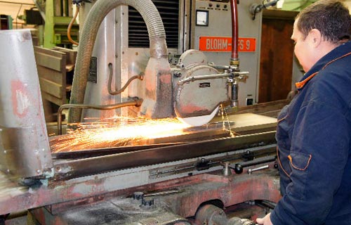
This procedure is performed in the following sequence.
VIDEO
In metal work, for the manufacture of cylindrical (conical) parts, a lathe is used. There are many models of this production device, and they all share almost the same layout of similar assemblies and parts. One of these is the machine support.
Homemade lathe
For a better understanding of the functions that the lathe support performs, you can consider its operation using the example of the common 16k20 model. After reviewing this information, perhaps some home craftsmen will have an idea to create a homemade lathe with their own hands for carrying out work on metal.
This is a rather complex node of a metal lathe, despite its apparent simplicity. From how correctly it is made, installed, adjusted - the quality of the future part depends, and the amount of time it took to make it.
The support placed on the 16k20 machine can move in the following directions:
transverse - perpendicular to the axis of the rotating workpiece for deepening into it;
longitudinal - the cutting tool moves along the surface of the workpiece to remove an excess layer of material or thread the thread;
inclined - to expand access to the surface of the workpiece at the desired angle.
The support for the 16k20 machine is located on the lower slide, which move along the guides fixed on the bed, and thus longitudinal movement occurs. The movement is set by the rotation of the screw, which converts the rotational force into translational movement.
The lathe support is designed to hold and move the cutting tool
On the lower slide, the caliper also moves transversely, but along separate guides (transverse slide) located perpendicular to the axis of rotation of the part.
A rotary plate is attached to the cross slide, with a special nut, on which there are guides for the movement of the upper slide. You can set the movement of the upper slide with a swivel screw.
The rotation of the upper slide in the horizontal plane occurs simultaneously with the plate. Thus, the installation of the cutting tool occurs at a given angle to the rotating part.
The machine is equipped with a cutting head (tool holder), which is fixed on the upper slide with special bolts and a separate handle. The movement of the caliper occurs along the lead screw, which is located under the travel shaft. This feed is done manually.
In the process of work on the 16k20 machine, there is natural wear and tear, loosening, loosening of the caliper fasteners. This is a natural process and its consequences must be constantly monitored through regular adjustments and adjustments.
The main components of the lathe
The following adjustments are made on the support of the 16k20 machine:
During the transverse and longitudinal movement of the support of the 16k20 machine tool along the slide, wear of the screw and their working surface occurs due to constant friction.
The presence of such free space leads to uneven movement of the caliper, jamming, oscillation during lateral loads that arise. Excessive clearance is removed using wedges, with which the carriage is pressed against the guides.
Backlash appears in the helical gear. You can get rid of it without disassembly. using the fixing screw, which is located on this caliper movement device.
During long-term work on metal on the 16k20 machine, wear and clogging of the oil seals occur, which are located at the ends of the carriage protrusion. Visually, this is determined when dirty stripes appear during the longitudinal movement of the caliper.
Lathe front cover with oil seal
In order to eliminate this phenomenon without disassembling the unit, it is necessary to rinse the felt padding and soak it with machine oil. If the worn out oil seals are completely unusable, they should be replaced with new ones.
This lathe device wears out over time under constant significant loads in metal work.
Significant wear is easily identified by the surface condition of the guide slide. Small depressions may appear on them, which will prevent the free movement of the caliper in a given direction.
With timely regular maintenance, such repairs may not be necessary, but in the event of a defect of this kind repair should be done, and in case of severe wear - replacement.
Caliper 16K20 quite often requires carriage repair, which consists in restoring the lower guides that interact with the bed guides. Particular attention is required to maintain a stable perpendicular position of the carriage.
When repairing the caliper, it is necessary to check on both planes using a building level.
The turning device with which metal work is done can be very simple. You can assemble a homemade machine with your own hands almost from improvised means, which are taken from mechanisms that have fallen into disrepair.
Homemade lathe
You should start with a metal frame welded from a channel, which will be the bed. From the left edge, a fixed front headstock is fixed on it, and a support is installed on the right. A self-made machine, made by hand, provides for a ready-made spindle with a chuck or faceplate.
The spindle receives torque from the electric motor through a V-belt transmission.
When the machine is working for metal, it is impossible to hold the cutter with your own hands (in contrast to working with wood), therefore, you will need a support that will move longitudinally. A tool holder is installed on it with the possibility of alternating it transversely to the direction of movement of the support itself.
The movement of the slide and the tool holder is set by the specified amount by means of a screw with a flywheel, which has a ring with metric divisions. The handwheel is manually driven.
VIDEO
In order to assemble a turning device with your own hands, you will need:
hydraulic cylinder;
shaft from the shock absorber;
corner, channel, metal beam;
electric motor;
two pulleys;
Belting.
Homemade lathe on a channel
A homemade lathe with your own hands is assembled in this way:
A frame structure is assembled from two channels and two metal beams. When working in the future with parts longer than 50 mm, materials with a thickness of at least 3 mm for the corner and 30 mm for the rods should be used.
The longitudinal shafts are fixed on two channels with guide rails with lugs, each of which is bolted or welded.
For the manufacture of the headstock, a hydraulic cylinder is used, the wall thickness of which must be at least 6 mm. Two bearings 203 are pressed into it.
A shaft is routed through bearings with an inner diameter of 17 mm.
Hydraulic the cylinder is filled with lubricant.
A nut with a large diameter is installed under the pulley to prevent the bearings from being squeezed out.
The finished pulley is taken from a used washing machine.
The caliper is made of a plate with cylindrical guides welded to it.
The chuck can be made from a piece of pipe of a suitable diameter, with nuts welded on it and holes made for 4 bolts.
The electric motor of the same washing machine (power 180 W), connected to the headstock by a belt drive, can serve as a drive.
The necessary information on the repair of a 1k62 screw-cutting lathe is indicated in the repair manual. Here you can also find information on the options for modernizing the machine.
There can be various kinds of malfunctions in the machines. Many of these arise from failure to follow care and maintenance instructions.
In any case, before proceeding with the elimination of the malfunction, you need to familiarize yourself with the list of the main possible malfunctions.
If the nature of the malfunction occurred is identical with the one described, you must use the proposed elimination methods.
If the nature of the malfunction does not coincide with those listed and its elimination is difficult, contact the factory.
The list of main faults is given in table 1, lubrication system faults in table 2.
The nature of the malfunction
Causes of occurrence
Elimination methods
Drop or lack of supply voltage
Check the presence and value of voltage in the network
It is impossible to switch the block of gears 9, 10 (Fig. 6) with the handle 5 (characteristic sound
The gear block does not move out of neutral
Switch on the electric motor and (freewheel) switch over
Arbitrary shutdown of the electric motor during operation
Thermal jet tripping due to motor overload
Reduce cutting speed and pi feed
Spindle torque is less than specified in the manual
Insufficient belt tension
Increase belt tension
Friction clutch loose
Braking is too slow
Weak brake band tension
Increase brake band tension
Caliper feed gain is less than specified in the manual
Insufficiently tightened reloading device spring
Repair and restoration of the TV-4 screw-cutting lathe.
The composition "Medium Rock" belongs to the performer Audionautix. License: Creative Commons Attribution (https://creativecommons.org/licenses/by/4.0/).
#LatheTV-4
If you assemble a homemade metal lathe with your own hands, you can get at your disposal functional equipment for metal processing at no extra cost. For objectivity, we will consider not only the assembly process, but also the current offers of the finished product market. The information below will help you make a correct comparative analysis, taking into account financial capabilities, professional skills and other personal characteristics.
High-quality homemade products are in no way inferior to the factory counterpart
Compact equipment does not take up much space in the home workshop
With the help of a table metal lathe, you can quickly and efficiently perform various working operations:
processing of ends, grooves with the required level of accuracy;
expansion of existing conical and cylindrical holes (countersinking);
accurate cutting of workpieces according to the length established by the plan;
creation of a relief surface by rolling;
cutting of standard and special threads (external / internal).
Complex and unique products can be created without mistakes using a metal lathe for the home
Study carefully the materials in this article. If it is difficult to implement the project with your own hands, knowledge will be useful for an objective assessment of the range of specialized stores. In separate sections there is information about the rules of operation that will help to extend the service life of technological equipment and provide a high level of safety.
Even a small lathe weighs a lot, creates vibrations during operation. A reliable base (1) is required, on which functional units and individual parts are fixed. If it is intended to create a floor version, use reliable supports of the required length. The final height of the work area should be user-friendly.
Other components are listed in the following list:
A gearbox is placed in the headstock (3). It is designed to adjust the speed of rotation of the spindle (4), change the magnitude of the torque.
On the reverse side, the workpiece is supported by a tailstock (6). Taps, drills, and other tools are also installed here, if necessary.
In the standard processing mode, the cutters are fixed in a special holder (5).
This assembly is mounted on a support (8). For smooth horizontal movement, a screw mechanism is used, located in the apron (7).
The feed box (2) drives the drive shaft.
the carriage (1) and the entire block as a whole (17) are driven by the travel shaft (2);
the movement mechanism is connected with a special handle (15);
these skids (3) provide freedom of movement of the upper part in the transverse direction (12);
it is fixed on the swivel unit (4) with longitudinal guides (5);
the cutters are installed in the holder (6);
screws (7/8) are used to secure this part / tools;
the handle (9) can safely move the cutters at a distance from the working area;
fastening element (10) of the upper part (11);
for its precise movement in the appropriate directions, use the handles (13, 14) with a screw drive;
the handwheel (16) is used to move the caliper manually.
In a detailed study of this part of a metal lathe, it is necessary to take into account the increased loads to which it is subjected in the process of performing technological operations. It is necessary to pay attention to the large number of moving components.
Sturdy parts are not the only thing needed to maintain precision. Constant adjustments will help eliminate backlash to compensate for wear. It is recommended to replace damaged seals with new products.
Hereinafter, we will consider projects that are easy to reproduce on their own with clarifying comments. The example in the picture is more suitable for woodworking equipment. To work with strong workpieces for a long time, you should make a support shoe from a steel plate.
In addition to the standard equipment, such interchangeable attachments come in handy.
With their help, the basic capabilities of the tailstock are expanded. In the author's recommendations, it is proposed to remove part of the standard holder of the cartridge (3). This will allow to increase the working stroke of the tool, to process larger workpieces.
For the manufacture of homemade products, simple design solutions are used.
A belt drive (1) is used here, which is notable for its low cost, low noise level. A double pulley (2) is installed for stepping the torque. To extend the life of the spindle (3), a pair of ball bearings must be used. If necessary, holes are made in the body for periodic filling of grease.
As a rule, a metal lathe is equipped with three-jaw chucks.
These clamps are automatically centered without additional adjustment. Self-production of such units will cause difficulties.Therefore, this functional element of the headstock of a lathe can be bought in a store.
Models with four jaws are used for processing square workpieces.
It is better to make the main part of the holder in a collapsible design.
This will allow you to make repairs without unnecessary difficulties. Screws are screwed into the threaded holes, which firmly fix the tool. The distance between the plates is determined taking into account the size of the cutters.
A handle is installed on top for quick rotation of the assembly. This device allows you to quickly change tools for complex sequential processing of workpieces.
Making a metal lathe with your own hands: step-by-step instructions with comments First stage: selection of a metal lathe device, preparation of project documentation The following drawings show the completed project. Such a relatively simple metal lathe for a garage (workshop) is not too difficult to make on your own. Belts and some other components are standard items. Other parts can be made by yourself or ordered from a specialized workshop.
Construction, main parts, dimensions
Headstock and tailstock components
Travel mechanism and support
Component parts of the carriage, assembly drawing
To select the required accuracy of movement of the caliper, the lead screw thread pitch is changed. It is cut into a die on a screw-cutting machine. To strengthen the structure, connections are made using welding. Headstock bodies are made from a channel (# 12/14).
The project presented above is designed for the use of a power unit with a capacity of 450-600 W with a maximum rotational speed of the working shaft - 2500-3500 rpm.
In order to save money, some project authors use old electric motors from out-of-order household appliances.
Such solutions are quite suitable if you choose a working engine of sufficient power.
The reasonable cost of products in this category allows you to easily find an acceptable option in the retail network. In this case, you can count on the official manufacturer's guarantees.
In order not to be mistaken, you can study examples of factory machine tools for metal, successful homemade products. Based on such a mini-study, it is easy to conclude about the following proportions: for processing parts with a diameter of 8-12 cm and a length of 60-80 cm, electric motors with a power of 600-800 W are used. Standard air-cooled asynchronous type models are suitable. It is not recommended to use collector modifications. They sharply increase the speed when the load on the shaft decreases, which will be unsafe. To prevent such situations, you will have to use a reducer, which will complicate the design.
Electrical diagram of a metal lathe
One advantage of the belt drive should be emphasized. It prevents direct mechanical impact on the shaft from the tool in the transverse direction. This extends the life of the journal bearings.
This algorithm explains the sequence of actions when working with the above drawings. The use of other design documentation implies the introduction of appropriate changes in the assembly process.
They start with the headstock. A spindle is installed in it. Further, the entire unit is connected to the running pipe using a bolt fastening. A thread is preliminarily cut on the fastening parts. When performing this operation, carefully control the alignment of the parts.
At the next stage, a power frame is assembled from the channels. When the frame is made, the headstock is installed on it. Here, too, the parallelism of the running tube and the long frame parts must be carefully monitored. Make the markup exactly. The holes are drilled sequentially with an additional reamer bore, checking each attachment point.One or two mistakes will not unduly compromise the strength of the channel, so it is better to make a new precise hole in a different place, if necessary.
For your information! Do not forget to install spring steel washers, which ensure the reliability of bolted connections in high vibration conditions.
Factory tailstock of a metal lathe
When assembling this unit, special attention should be paid to the accuracy of the placement of the central axes of the spindle (1) and quill (2). If a mistake is made, conical surfaces will be obtained instead of cylindrical when machining workpieces. Also check the parallelism of these elements to the running pipe. The support bar (3) prevents the tailstock from unfolding. Steel spacers can be used for height adjustment.
Caliper parts are installed sequentially in accordance with the assembly drawing diagram. Particularly high precision is not needed here, since numerous adjustments are provided. If intensive use is expected, make individual units detachable in order to replace wearing parts at no extra cost.
At the final stage, an electric motor is installed, connected to the mains according to the selected scheme. They check the functionality of a metal lathe with their own hands in practice. To improve the appearance and protect against corrosion, some parts are coated with primer and paint.
This photo of a metal lathe clearly demonstrates the high quality of homemade products.
Video (click to play).
For processing workpieces made of wood, plastic, and other soft materials, the power of a typical household power tool is enough. This example describes how to make a functional machine with your own hands in 15-20 minutes. With the help of the last photos, the table tells about the creation of an improved design:

