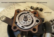
In detail: do-it-yourself Bosch fuel pump repair from a real master for the site my.housecope.com.
The injection pump number 059 130 106D was installed on cars:
Volkswagen Passat B5.5 / Volkswagen Passat B5.5 (3B3) 2001 - 2005
Volkswagen Passat Variant B5.5 / Volkswagen Passat Variant B5.5 (3B6) 2001 - 2005
Volkswagen Passat B5 / Volkswagen Passat B5 (3B2) 1997 - 2001
Volkswagen Passat Variant B5 / Volkswagen Passat Variant B5 (3B5) 1997 - 2001
Audi A4 B5 / Audi A4 B5 (8D2) 1995 - 2001
Audi A4 Avant B5 / Audi A4 Avant B5 (8D5) 1996 - 2002
Audi A6 C5 / Audi A6 (4B2) 1997 - 2005
Audi A6 Avant / Audi A6 Avant (4B5) 1998 - 2005
information is suitable for repairs and other cars.
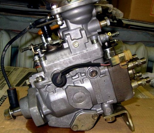
Hello everyone! I decided to write a report on self-repair of the Bosch VP44 injection pump, number 059 130 106D, auto Audi A8 D2 2.5tdi V6, but this pump was not installed anywhere, Audi A4, A6, VW, BMW, Opel, often breaks down on trucks - so I think the information will not hurt.
I had no experience with high-pressure fuel pumps - so I bombarded specialists with questions on various forums - thanks to everyone who helped with advice!
A big role was played by the report of the owner of the Opel Vectra - Mitrofana (Thank you). The progress of the disassembly process is displayed there.
I want to tell you about my experience and my own “rakes” so that no one would jump on them again.
So, after pumping with a pear or something from the nozzle pipes, nothing presses when scrolling with the starter - it means you have problems with mechanics: the most likely option is damage to the membrane (or cutting rings), the second option is a defect in the booster pump ... You will see all this later in the photo.
Anyone who has everything working properly - here you can view the high-pressure fuel pump from all angles, incl. his most intimate places
| Video (click to play). |
To begin with, while the pump is on the machine, we set the timing and injection pump to the “base” position so that the hole for the stopper coincides with the hole on the pulley (we shine a flashlight), you can rotate the timing either by the crankshaft or by the camshaft (but with a force of no more than 75 Nm (! ), smoothly, with pauses, or with a gearbox, hanging out the muzzle, rotating the wheel. Then loosen the nut by 27mm of the gear wheel, put a clear mark on the shaft and the gear wheel. We may need it when reassembling. The tooth itself. The wheel sits firmly on the "cone "- even without a nut, it won't move a single gram, you don't need to press it yet, so far we only need a mark with an awl:
The decision on whether to compress it or not will be made later (so as not to do unnecessary work).
Then we unscrew the pump from the auto - we close the fitting with something and thoroughly rinse it with a “karcher”, then blow it in places with a carb cleaner and blow it with compressed air so that there is less dirt during disassembly:
We unscrew the "brains" and 2 e-mail. valve (details at Mitrofan), for this we need Torx 10,25,30 (later another T20 is possible). Before unscrewing, knock on the Torx with a small hammer, if it does not work, it is better to continue knocking, because when you break the edges, you will have to drill and drive in the “M” bit.
When pulling out the central valve (with a screwdriver as a lever), you need to make sure that it comes out without skewing, if it skews, push it back and again try supporting it from below.
Then we bring the gear wheel (which is still firmly sitting on the cone) to the mark into which the stopper is inserted (or, as for a collective farm, a 6mm drill), unscrew the T50 bolt, remove the washer under it and tighten it all the way, thereby blocking the movement of the shaft, the stopper take out:
In this case, the back will be in this position:
Further, to remove the distributor head according to Mitrofan, we burst and swing with screwdrivers, but I, so as not to spoil the al. the body simply rested with a screwdriver and knocked down with a hammer:
We remove the distribution head and see the very defect due to which the pressure disappeared - damage to the outer plastic part of the membrane:
If you saw such a picture (or just a crack), then you don't need to disassemble further - we change the membrane and rubber rings and put them back together. Membrane repair kit Bosch 1 467 045 032. But there are important nuances, read here
Since I did not immediately notice due to inexperience, I disassembled further:
Further, to remove the bearing according to Mitrofan, we pull it with a thick wire, I just spread the newspaper on the floor and hit it with the body - by inertia the bearing and 2 washers came out:
Then you need to unscrew the plug, wrap the top with paper or a rag and pull out with pliers:
With drifts or something handy, we turn the cam washer and the piston to the position at which the cool. the washer will move up (in the photo you need to turn it a little clockwise and it will rise):
After removing the cooler. washers - we take out the piston - this is how it looks from all sides (if it comes out badly, you can swing it with drifts for 2 holes, which are in the photo at the top left, but do not stick it deep into the hole):
Now we press the gear wheel off the shaft (while the shaft is "pressed in" Torx50, which was mentioned above, otherwise, when removed, the shaft will shoot like a bullet - both the shaft and the housing can be damaged). You will need a GOOD puller, the effort is HUGE, we put good pieces of rags under the puller's paws, so as not to leave “jammed”.
After pressing, we loosen T50 and take out the shaft.
... and the puck (what's underneath). The booster pump remains in the housing.
Now, using T20, unscrew the bolts (you need a long and thin T20, preferably):
It is desirable to “shake it out” by hitting the body on the newspaper - then it will fall out “assembled”. If you try to push from behind with your fingers, it will most likely fall out "in parts", this is bad:
As they say, it is undesirable to confuse the blades in places, otherwise they can wedge at revolutions.
Another photo of him:
It is serviceable, the only thing there is a small defect - chipping, but this is not criminal:
The booster pump was taken from the spare donor pump, it fell out “assembled”, we rinse very well. carba:
Then the empty body was washed with "Karcher" (without bringing it close to the channels), then och. Carba dried through channels and compressed air. Purity:
Install the booster pump (donor) in place:
We put the washer and insert the shaft (in the photo the washer hangs on the shaft):
The gear wheel is ready for installation:
Align it according to our scratch mark with the shaft, then rotate it until the hole for the stopper is aligned and block T50:
Slightly (!) Fill the tooth. the wheel onto the shaft, lightly tighten the nut by 27mm. We put catalogs and a tooth damper on the table. wheels to position the injection pump conveniently for further assembly.
In this case, the picture is as follows, the shaft is locked in the “basic” position:
The piston was taken from the donor pump, the scratches were slightly sanded with the P800, 1500, 2000 legs. It is advisable to grind the sleeve itself in the injection pump housing with P2000 (but this is before washing).
As you can see on the left - the piston ring interferes with the assembly - just wrap the piston with plastic wrap, squeeze it with your fingers and put it on:
Place the piston so that the cam washer is “filled” into it (yellow arrow). The second point of connection is cool. washers - black arrow:
And here is the cam washer itself, these 2 pins must be “inserted” into the holes:
There is no more complex and critical unit in a diesel engine than the fuel injection system, more precisely, its main part - the high pressure fuel pump. Many mating parts, high-loaded units, the presence of a precision dosing system, make the repair of the injection pump a difficult task even in service conditions. It is all the more difficult to repair the high pressure fuel pump of a diesel engine with your own hands.
In automotive technology, almost everything is repaired, except, perhaps, individual oil seals and cuffs, the repair of which is impossible without special materials. The complexity of setting, diagnosing and repairing the injection pump requires the employee to have skills in working with precision mechanics.
It is simply impossible to adjust according to the factory parameters, without a special diagnostic stand for the repair of the injection pump. During the diagnostic study of the injection pump, it is necessary to check:
- cyclic supply of the high-pressure pump, in the entire range of revolutions of the injection pump shaft, at start-up, and after cutting off the fuel supply;
- stability of the developed pressure;
- uniformity of the injection pump delivery to the fuel injector.
Even having access to a diagnostic stand, and having studied the issue of repairing a high-pressure fuel pump using numerous videos, it is very difficult to qualitatively check and evaluate its work.
In heavy diesel engines, plunger, in-line injection pumps are used. In maintenance and repair, such devices are more difficult, since they require special equipment for its disassembly, therefore we will not consider such high pressure fuel pumps and their repair.
In a passenger diesel engine, a distribution type injection pump is almost always used. Unlike in-line pumps, in a distribution pump, the force is transmitted to the plunger using a profiled cam washer. The design of the injection pump turned out to be more compact, but it is hardly simpler to expect to carry out its repair on the knee.
The most famous and affordable is the Bosh VP44 injection pump. Often, the need to repair the pump internals arises when:
- poor traction and incomplete combustion of fuel even under ideal conditions - in the absence of load and a thoroughly warmed up engine;
- a sudden failure and stoppage of a diesel engine under load, which is called “death on takeoff”. Usually the scanner in such cases diagnoses the code P1630 and P1651.
- the appearance of a diesel fuel leak in the area of the gland seal of the central shaft of the injection pump.
Therefore, we will restrict ourselves to the issue of repairing the injection pump with our own hands by replacing the seals and eliminating the scoring of the working surfaces of the parts.
Before disassembling the pump drive shaft seal, try to move it radially. If play is felt with your hands, it is possible that the reason for the leakage of fuel is the wear of the working surface of the shaft or requires repair of the bearing.
A large number of split planes and mating surfaces of parts required the use of a large number of seals and glands. As a rule, they are made of quality material and last long enough until they are damaged during repair or maintenance. In this case, standard repair kits are used for DIY repair of Bosch injection pumps.
It is quite easy to replace the seal on the shaft position sensor and on the automatic injection timing during repairs. For a better fit, you can drip a few drops of spindle or engine oil onto new rings and rubber bands.
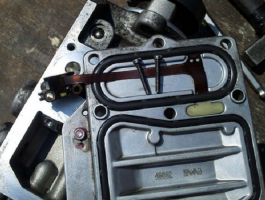


For preventive repair of a Bosch injection pump with your own hands, you will need to disassemble the pump in approximately the following order:
- remove the metering valve from the end of the injection pump. To do this, unscrew the four screws of the pressure plate, carefully release the cable of the injection advance valve. By removing the three screws securing the metering valve, you can carefully remove it from the seat;
- by unscrewing the fastener on the top cover, you can remove the control board and gain access to the electronics;
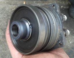
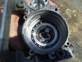
- we set the position of the shaft, as shown in the photo, remove the camera and get access to the insides of the injection pump;
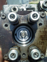
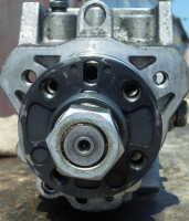

- after dismantling the bearing using a special puller, we get the opportunity to study the potential culprit for the poor performance of the injection pump - the piston of the injection advance unit. There is often surface wear and edge scuffing on the part. You can try to make repairs by polishing the surface, replacing the whole part is much more expensive.

After the repair, the assembly is carried out in the reverse order with the washing of the parts with diesel fuel.
Often, in addition to scoring, on the surface of the pistons there is another reason why the injection pump does not develop the required pressure. This can be due to debris, films or wax build-up on the filter screen inside the pump. There is a mesh on the side of the inlet pipe. Rinsing the channels is a troublesome and ineffective business, it is easier to remove the mesh and blow it with compressed air.
Torn pieces of debris can jam the plunger piston or even break or break the pump drive shaft. Therefore, cleaning should be done very carefully to avoid contamination of the internal cavities of the pump.
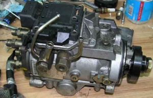
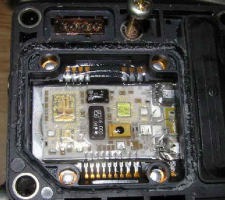
Among the many reasons for the failure of the electronic "liver" of the injection pump, the most common is the breakage or burnout of the contacts of the control board and the failure of power transistors. If the knowledge and skills of working with electronic devices allow to carry out a "continuity" of the transistor performance and repair, it is worth trying to identify the cause and replace the culprit with a serviceable element.
To check the condition of the "culprit", you need to carefully open the black cover, which is tightly seated on the rubber seal with screws. It should be removed carefully so as not to damage the seal itself.




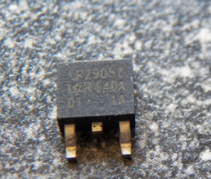


The reason for the failure of not only the transistor, but also the entire board could be air trapped in the cavity due to poor performance of the drainage system or the check valve. Often, they try to eliminate the airing by spinning up with a starter, hoping to pump diesel fuel into the high-pressure fuel pump in this way. At this moment, the transistor is open and loaded as much as possible, which leads to intense heating. In an air environment with poor heat dissipation, it will inevitably burn out. In some German cars there is a protection that prevents an attempt to start the engine in the absence of fuel in the highway. For this, a fuel sensor in the tank is used.
Failure of the transistor can be established by "dialing" a tester or by its appearance. The best option for repairing such a malfunction would be to replace the entire control board. Perhaps it is more expensive than soldering, but it will give guaranteed quality and stable operation of the injection pump after repair. As a last resort, give the board and the transistor for soldering to electronics specialists.
When installing and reassembling after repairs, check the tightness of all fasteners.
If during the audit you did not make rash and unreasonable replacements of parts, the assembled pump should work with approximately the same parameters as before. Bosch EPS-815 stand is used as a standard for testing and adjusting injection pump after overhaul.
The video shows how to raise the plunger pressure in a Bosch VE injection pump:
Attention, the editors of the site "Your Road" recommend that you consult with a specialist before applying this instruction to action.
One of the most mysterious parts of a car with a diesel engine is a high-pressure fuel pump (TNVD). There are 2 types of pumps - a mechanical pump and an electronically controlled pump, popularly EFI-shny. Each of the types is divided into 2 subspecies: Multi-plunger in-line, single-plunger distribution type (VE). We will not consider the "exotic" type of pump-injector, Common Rail or VR series distribution pumps (Distribution pump with axial plunger, Distribution rotary injection pump)
Since the device, and therefore the principle of its operation, is a mystery for many, there is an opinion that specialized equipment and a specially trained person are needed to repair it. However, such a "gentleman's" set is not always at hand, so let's try to disassemble and assemble this tricky knot "on the knee". The object for preparation will be a high-pressure fuel pump, assembled in ancient times from several different-sized pumps, without using stands, but at the same time successfully spinning a 4D56 diesel engine WITHOUT TURBINE up to 8000 rpm. Externally, it can differ from the high-pressure fuel pump installed on your car only in the absence of a pressure corrector (a kind of mushroom-hat on the top cover) and some attachments. This does not change the essence of the matter.
So, on the table- OH .. Top view
Colored arrows indicate:
- Green - fuel supply bolt
- Yellow - "return"
- Black - pressure valve in the injection pump housing
- Red - the axis of the fuel supply regulator ("gas" drive).The "gas" lever itself has been dismantled for convenience.
- Brown - mixture "quality" bolt.
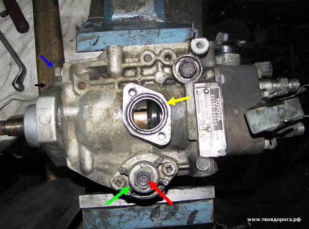
Arrows indicate:
- Black - automatic heating
- Green - drive of the automatic heating device
- Red - automatic ignition timing (injection)
- Blue - identification plate
Side view (back side):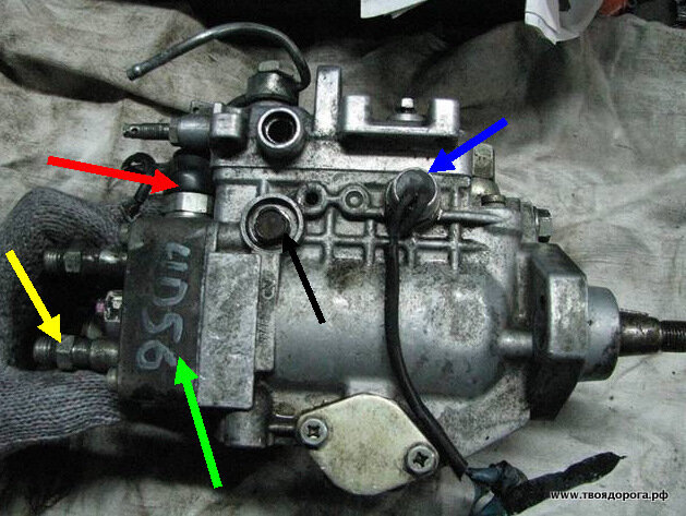
- Blue - speed sensor (tachometer, not always present)
- Red - fuel cut-off valve (muffler)
- Yellow - pressure valve.
- Green is the plunger itself.
- Black - the axis of the fuel lever. The same is available on the back of the pump. It is better to remove (but not completely unscrew) them at the initial stage of disassembly.
For work you will need: a set of heads, a set of hexagons, tweezers, screwdrivers, a gas wrench, a caliper, a vice, a clean rag, a container with clean diesel fuel, a grease (Litol, CV joint, etc.) -))
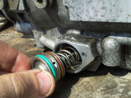
- A mesh filter is installed inside, which, as a rule, cannot be washed. Removal has no “contraindications” (yellow arrow).
- Has a calibrated hole on the side surface (red arrow). Different pumps have different sizes, so replacing them with another leads to a change in the internal pressure in the pump.
I think no comments are needed. Council - the drive itself should not be disassembled.
- Yellow - speed sensor
- Green - "jammer".
- Black - centrifugal speed controller.
- Blue - fuel drive lever.
Here one difficulty is to get to one of the 3 bolts. There are only two options:
Disassemble the drive (carefully, there is a powerful spring! + REMEMBER the setting of the adjusting bolt), and then calmly unscrew the rest.
Unscrew 2 "light" bolts under the key "by 10", loosen the third, "heavy" one, and pushing the assembly aside, slowly unscrew it.
It should look like this:
- Yellow - O-ring
- Red- adjusting bolt of the automatic advance switch
- Green - the cover of the advancing machine.
- Remember (write down) the bolt head protrusion (red arrow) above the cover (green arrow). If in the process you decide to unscrew this bolt, during assembly it will be necessary to return the dimensions to their original state.
- Blue - the axis of the speed regulator.
- Black - mating plane.
Attention! For pumps with RIGHT rotation, the thread on the shaft will be LEFT and vice versa!
If you can find a tool, unscrew the pressure regulator.
Now the fun begins. Parsing includes nodes consisting of several parts. Moreover, the details cannot "live" without each other. That is, they simply cannot be confused with each other.
- Red - pressure valve body
- Green - spring returnable
- Blue - valve needle
- Yellow - valve seat
- Black - sealing washer.
The plug under the red arrow does not need to be unscrewed; it serves to install the indicator. The fact is that the ignition on diesels is placed not so much on the marks. Rather, initially, the moment of injection is set according to the indicator, and only then the mark that we see is applied. We will omit this procedure for now, the turn will come to it.
So, turn off the cap (blue arrow). This is where the gas wrench comes in handy. The thread of the plug is right-hand.
- Blue - plunger body
- Red - plunger.
At this stage, it is necessary to measure the amount by which the plunger sinks into the body. We measure the results, write them down, they will come in handy during assembly.
We release the fastening screws (but not completely), and gently shaking, we move the plunger body up. As soon as it is free, we finally unscrew the screws and remove the plunger body. You should get the following picture:
- Blue - plunger
- Yellow - dosing ring
- Red - washer - bearing
- Brown - base plate
- Black - spring
- Green - adjusting washers.
- Black - Plunger Shim
- Red - cam washer.
- Green - fuel delivery lever. I managed to take it off earlier.
Attention!! We do not remove the videos, we do not change them in places.
Remove the stopper (shown with a screwdriver).
We see a pin under the stopper.Shown also with a screwdriver (it is magnetized, the pin can be easily removed by it).
Remove the cam washer drive.
In the interior of the vacated space, push the axis of the advancing automaton:
For convenience, I deleted 1 video, there is nothing criminal here. Pull the roller ring outward for the axis of the advancing automaton. Caution, do not use unnecessary effort! At the slightest misalignment, the ring wedges in the body. Attempts to pull it out "insolently" will end in disrepair - the pump casing will be scrapped.
It should look something like this:
For the 2 "horns" sticking out in the depths of the pump, we take out the pump shaft with the gear of the regulator:
We return to the "remains" of the pump:
We release the bolts (blue arrows) and take out the booster pump cover (red arrow).
We turn over the pump housing.
We remove the oil seal (shown with a screwdriver). Warning - don't try to save it, it won't work anyway.
As a result, a bare body with a bushing pressed into it should remain. Like this:
The high pressure fuel pump is one of the most complex components of the diesel engine fuel supply system.
The principle of operation of the injection pump is to supply precisely measured portions of the fuel mixture to the cylinders of a diesel engine at a certain moment and under a certain pressure, which correspond to a given load.
In direct-acting fuel pumps, the plunger is mechanically driven, and the process of the injection and pumping takes place simultaneously. The required portion of the fuel mixture is supplied to all cylinders by the injection pump section. The required pressure for injection and atomization is provided by a plunger pump. In the article we have presented, we will talk in more detail about this part of the manufacturer bosch, namely, we will consider such fairly common questions:
- Where to buy injection pumps and accessories?
- What is a high pressure fuel pump?
- High pressure fuel pump device;
- What is the principle of operation of the Bosch injection pump?
- Bosch in-line injection pump device;
- How to properly disassemble a bosch injection pump?
- Bosch plunger injection pump, its structure and principle of operation;
- The principle of operation of the moment of injection of the high-pressure fuel pump from bosch;
- Installation of injection pump bosch.
So, what is the principle of the injection pump? The principle of operation of the Bosch injection pump, as well as the injection moment, is no different from the injection pump of other manufacturers. The main element of the Bosch injection pump is a plunger pump. The fuel pump is designed to transfer a certain portion of fuel to the engine under high pressure and to prevent two extremes, such as its lack and excess. Therefore, breakdowns that the car owner may not pay attention to or evaluate them as insignificant, can lead to the repair of the diesel engine or its complete replacement. The main criterion by which fuel pumps are divided into types is their design. So, on the basis of the device of the fuel pumps, they are divided into the following types:
- Distribution. Equipped with mechanical nozzles and regulators. Modern motors are equipped with electrically controlled in-line injection pumps (high pressure fuel pump). The presented type of pumps is considered the simplest, although it is distinguished by significant dimensions and weight characteristics;
- In-line. Equipped with one or more plunger pairs that inject the fuel mixture and distribute it to the cylinders. This type is much smaller and lighter than in-line. Although this advantage leads to some disadvantages, for example, rapid wear of distribution-type parts;
- Trunk. Typically, they are used in the commonrail injection system. Their main and only function is to pump the fuel mixture into the rail. The number of plungers ranges from one to three. This type of injection pump also uses parts such as a washer or cam shaft that drive the plungers.
A fairly obvious fact is that without the use of a high-pressure fuel pump, it would be difficult to supply fuel to the engine. That is why it is quite logical that so much attention is paid to this type of fuel pump by motorists who are engaged in the repair of engines of this type.
The most common causes of problems are:
- The use of low-quality fuel, and this can lead to damage to the fuel pump. Diesel fuel is used for high pressure fuel pumps, as a lubricant for moving parts and plunger pairs. In the case of fuel contamination with various impurities, the lubricating property is lost, and this can lead to a malfunction of the fuel pump in the future;
- Fuel pump worn out;
- Problems with electrical appliances. Improper functioning of the vehicle electronics can affect the normal functioning of other systems.
In order to qualitatively repair the high-pressure fuel pump, you need to know how the disassembly and installation is carried out, when the restoration of the high-pressure fuel pump is impossible and which parts need to be replaced in order to troubleshoot. So, how is the high pressure fuel pump disassembled and installed correctly?
- Unscrew the 4 screws on the front side;
- Release the injection timing valve cable from under the pressure plate;
- Unscrew the 3 screws that secure the pressure plates of the metering valve;
- Remove the metering valve;
- Unscrew the 2 screws that secure the injection timing valve;
- Remove the injection advance valve;
- Unscrew the screws that secure the so-called brains;
- Move aside the brains and unscrew the screws that secure the fuel pump roller position sensor;
- Take off the brains along with the liver;
- Place a pulley on the mark and note the position of the roller along with the metering needle;
- Using two flat screwdrivers, laying them in pairs-diametrically behind the ears, carefully the camera together with the fittings;
- Take out the bearing and plates;
- Unscrew the cover of the advance machine;
- Take out the automatic injection advance;
- Install the advance piston so that the cam washer can be removed from it during turning;
- Take out the injection advance piston;
- The fuel pump is disassembled and assembled upside-down.
Website for cars and repair.
There is no more complex and critical unit in a diesel engine than the fuel injection system, more precisely, its main part - the high pressure fuel pump. Many mating parts, high-loaded units, the presence of a precision dosing system, make the repair of the injection pump a difficult task even in service conditions. It is all the more difficult to repair the high pressure fuel pump of a diesel engine with your own hands.
In automotive technology, almost everything is repaired, except, perhaps, individual oil seals and cuffs, the repair of which is impossible without special materials. The complexity of setting, diagnosing and repairing the injection pump requires the employee to have skills in working with precision mechanics.
It is simply impossible to adjust according to the factory parameters, without a special diagnostic stand for the repair of the injection pump. During the diagnostic study of the injection pump, it is necessary to check:
- cyclic supply of the high-pressure pump, in the entire range of revolutions of the injection pump shaft, at start-up, and after cutting off the fuel supply;
- stability of the developed pressure;
- uniformity of the injection pump delivery to the fuel injector.
Even having access to a diagnostic stand, and having studied the issue of repairing a high-pressure fuel pump using numerous videos, it is very difficult to qualitatively check and evaluate its work.
In heavy diesel engines, plunger, in-line injection pumps are used. In maintenance and repair, such devices are more difficult, since they require special equipment for its disassembly, therefore we will not consider such high pressure fuel pumps and their repair.
In a passenger diesel engine, a distribution type injection pump is almost always used.Unlike in-line pumps, in a distribution pump, the force is transmitted to the plunger using a profiled cam washer. The design of the injection pump turned out to be more compact, but it is hardly simpler to expect to carry out its repair on the knee.
The most famous and affordable is the Bosh VP44 injection pump. Often, the need to repair the pump internals arises when:
Therefore, we will restrict ourselves to the issue of repairing the injection pump with our own hands by replacing the seals and eliminating the scoring of the working surfaces of the parts.
Before disassembling the pump drive shaft seal, try to move it radially. If play is felt with your hands, it is possible that the reason for the leakage of fuel is the wear of the working surface of the shaft or requires repair of the bearing.
A large number of split planes and mating surfaces of parts required the use of a large number of seals and glands. As a rule, they are made of quality material and last long enough until they are damaged during repair or maintenance. In this case, standard repair kits are used for DIY repair of Bosch injection pumps.
It is quite easy to replace the seal on the shaft position sensor and on the automatic injection timing during repairs. For a better fit, you can drip a few drops of spindle or engine oil onto new rings and rubber bands.


For preventive repair of a Bosch injection pump with your own hands, you will need to disassemble the pump in approximately the following order:
- remove the metering valve from the end of the injection pump. To do this, unscrew the four screws of the pressure plate, carefully release the cable of the injection advance valve. By removing the three screws securing the metering valve, you can carefully remove it from the seat;
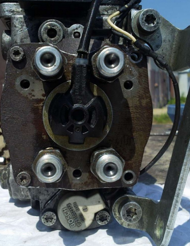
- by unscrewing the fastener on the top cover, you can remove the control board and gain access to the electronics;
- we set the position of the shaft, as shown in the photo, remove the camera and get access to the insides of the injection pump;


- after dismantling the bearing using a special puller, we get the opportunity to study the potential culprit for the poor performance of the injection pump - the piston of the injection advance unit. There is often surface wear and edge scuffing on the part. You can try to make repairs by polishing the surface, replacing the whole part is much more expensive.


After the repair, the assembly is carried out in the reverse order with the washing of the parts with diesel fuel.
Often, in addition to scoring, on the surface of the pistons there is another reason why the injection pump does not develop the required pressure. This can be due to debris, films or wax build-up on the filter screen inside the pump. There is a mesh on the side of the inlet pipe. Rinsing the channels is a troublesome and ineffective business, it is easier to remove the mesh and blow it with compressed air.
Torn pieces of debris can jam the plunger piston or even break or break the pump drive shaft. Therefore, cleaning should be done very carefully to avoid contamination of the internal cavities of the pump.
Among the many reasons for the failure of the electronic "liver" of the injection pump, the most common is the breakage or burnout of the contacts of the control board and the failure of power transistors. If the knowledge and skills of working with electronic devices allow to carry out a "continuity" of the transistor performance and repair, it is worth trying to identify the cause and replace the culprit with a serviceable element.
Often the reason for the failure of the injection pump dosing valve is not the valve itself, but the control electronics. More precisely, a power transistor responsible for supplying a control pulse to the valve.
To check the condition of the "culprit", you need to carefully open the black cover, which is tightly seated on the rubber seal with screws. It should be removed carefully so as not to damage the seal itself.


The reason for the failure of not only the transistor, but also the entire board could be air trapped in the cavity due to poor performance of the drainage system or the check valve.Often, they try to eliminate the airing by spinning up with a starter, hoping to pump diesel fuel into the high-pressure fuel pump in this way. At this moment, the transistor is open and loaded as much as possible, which leads to intense heating. In an air environment with poor heat dissipation, it will inevitably burn out. In some German cars there is a protection that prevents an attempt to start the engine in the absence of fuel in the highway. For this, a fuel sensor in the tank is used.
Failure of the transistor can be established by "dialing" a tester or by its appearance. The best option for repairing such a malfunction would be to replace the entire control board. Perhaps it is more expensive than soldering, but it will give guaranteed quality and stable operation of the injection pump after repair. As a last resort, give the board and the transistor for soldering to electronics specialists.
When installing and reassembling after repairs, check the tightness of all fasteners.
If during the audit you did not make rash and unreasonable replacements of parts, the assembled pump should work with approximately the same parameters as before. Bosch EPS-815 stand is used as a standard for testing and adjusting injection pump after overhaul.
Website for cars and repair.
There is no more complex and critical unit in a diesel engine than the fuel injection system, more precisely, its main part - the high pressure fuel pump. Many mating parts, high-loaded units, the presence of a precision dosing system, make the repair of the injection pump a difficult task even in service conditions. It is all the more difficult to repair the high pressure fuel pump of a diesel engine with your own hands.
In automotive technology, almost everything is repaired, except, perhaps, individual oil seals and cuffs, the repair of which is impossible without special materials. The complexity of setting, diagnosing and repairing the injection pump requires the employee to have skills in working with precision mechanics.
It is simply impossible to adjust according to the factory parameters, without a special diagnostic stand for the repair of the injection pump. During the diagnostic study of the injection pump, it is necessary to check:
- cyclic supply of the high-pressure pump, in the entire range of revolutions of the injection pump shaft, at start-up, and after cutting off the fuel supply;
- stability of the developed pressure;
- uniformity of the injection pump delivery to the fuel injector.
Even having access to a diagnostic stand, and having studied the issue of repairing a high-pressure fuel pump using numerous videos, it is very difficult to qualitatively check and evaluate its work.
In heavy diesel engines, plunger, in-line injection pumps are used. In maintenance and repair, such devices are more difficult, since they require special equipment for its disassembly, therefore we will not consider such high pressure fuel pumps and their repair.
In a passenger diesel engine, a distribution type injection pump is almost always used. Unlike in-line pumps, in a distribution pump, the force is transmitted to the plunger using a profiled cam washer. The design of the injection pump turned out to be more compact, but it is hardly simpler to expect to carry out its repair on the knee.
The most famous and affordable is the Bosh VP44 injection pump. Often, the need to repair the pump internals arises when:
Therefore, we will restrict ourselves to the issue of repairing the injection pump with our own hands by replacing the seals and eliminating the scoring of the working surfaces of the parts.
Before disassembling the pump drive shaft seal, try to move it radially. If play is felt with your hands, it is possible that the reason for the leakage of fuel is the wear of the working surface of the shaft or requires repair of the bearing.
A large number of split planes and mating surfaces of parts required the use of a large number of seals and glands. As a rule, they are made of quality material and last long enough until they are damaged during repair or maintenance. In this case, standard repair kits are used for DIY repair of Bosch injection pumps.
It is quite easy to replace the seal on the shaft position sensor and on the injection timing machine during repairs. For a better fit, drip a few drops of spindle or engine oil onto new rings and rubber bands.


For preventive repair of a Bosch injection pump with your own hands, you will need to disassemble the pump in approximately the following order:
- remove the metering valve from the end of the injection pump. To do this, unscrew the four screws of the pressure plate, carefully release the cable of the injection advance valve. By removing the three screws securing the metering valve, you can carefully remove it from the seat;

- by unscrewing the fastener on the top cover, you can remove the control board and gain access to the electronics;
- we set the position of the shaft, as shown in the photo, remove the camera and get access to the insides of the injection pump;


- after dismantling the bearing using a special puller, we get the opportunity to study the potential culprit for the poor performance of the injection pump - the piston of the injection advance unit. There is often surface wear and edge scuffing on the part. You can try to make repairs by polishing the surface, replacing the whole part is much more expensive.


After the repair, the assembly is carried out in the reverse order with the washing of the parts with diesel fuel.
Often, in addition to scoring, on the surface of the pistons there is another reason why the injection pump does not develop the required pressure. This can be due to debris, films or wax build-up on the filter screen inside the pump. There is a mesh on the side of the inlet pipe. Rinsing the channels is a troublesome and ineffective business, it is easier to remove the mesh and blow it with compressed air.
Torn pieces of debris can jam the plunger piston or even break or break the pump drive shaft. Therefore, cleaning should be done very carefully to avoid contamination of the internal cavities of the pump.
Among the many reasons for the failure of the electronic "liver" of the injection pump, the most common is the breakage or burnout of the contacts of the control board and the failure of the power transistors. If the knowledge and skills of working with electronic devices allow to carry out a "continuity" of the transistor performance and repair, it is worth trying to identify the cause and replace the culprit with a serviceable element.
Often the reason for the failure of the injection pump dosing valve is not the valve itself, but the control electronics. More precisely, a power transistor responsible for supplying a control pulse to the valve.
To check the condition of the "culprit", you need to carefully open the black cover, which is tightly seated on the rubber seal with screws. It should be removed carefully so as not to damage the seal itself.


The reason for the failure of not only the transistor, but also the entire board could be air trapped in the cavity due to poor operation of the drainage system or the check valve. Often, they try to eliminate the airing by spinning up with a starter, hoping to pump diesel fuel into the high-pressure fuel pump in this way. At this moment, the transistor is open and loaded as much as possible, which leads to intense heating. In an air environment with poor heat dissipation, it will inevitably burn out. In some German cars there is a protection that prevents an attempt to start the engine in the absence of fuel in the highway. For this, a fuel sensor in the tank is used.
Failure of the transistor can be established by "dialing" a tester or by its appearance. The best option for repairing such a malfunction would be to replace the entire control board. Perhaps it is more expensive than soldering, but it will give guaranteed quality and stable operation of the injection pump after repair. As a last resort, give the board and the transistor for soldering to electronics specialists.
When installing and reassembling after repairs, check the tightness of all fasteners.
| Video (click to play). |
If during the audit you did not make rash and unreasonable replacements of parts, the assembled pump should work with approximately the same parameters as before.Bosch EPS-815 stand is used as a standard for testing and adjusting injection pump after overhaul.

