In detail: do-it-yourself high-pressure fuel line repair from a real master for the site my.housecope.com.
Repair of fuel lines. Low-pressure fuel lines made of copper pipes and high-pressure fuel lines made of thick-walled steel pipes have the following defects: wear of surfaces at the points of contact with fittings and nuts, cracks, fractures, abrasions and dents.
Fuel lines received for repair are washed with hot cleaning solution and blown with compressed air.
The tightness of the low pressure fuel line is checked in a water bath. One end of the fuel line is plugged with a plug, and air is pumped through the other with a pump. By the bubbles emerging from the tube, the damaged area is determined, which is then soldered with soft solder.
A broken or frayed fuel line is restored with a coupling. In this case, the ends of the pipe joints are cleaned, and the ends of the connecting sleeve made of a tube of a larger diameter are carefully soldered and checked for tightness.
The worn ends of the fuel lines are cut off and, using a special device, new working surfaces are made as follows. The tube is annealed, that is, the tube is heated and lowered into water, then inserted into the hole of the clamping jaws corresponding to the tube diameter, and clamped with clamping screws so that the end of the tube protrudes 3 ... 4 mm. Turning the screw of the device, the end of the tube is expanded to the required size.
Broken or frayed high pressure fuel lines are gas welded. The ends to be joined are carefully leveled and chamfered before welding.
The worn ends of the tubes are cut off and planted using a special device under a press.
| Video (click to play). |
The restored fuel line is tested for hydraulic resistance (flow capacity) on a special device. The difference in the hydraulic resistance of the fuel lines of one set is allowed no more than 10%.
Repair of fuel tanks. The main defects of fuel tanks are as follows: cracks on the walls, in the attachment points of the filler neck, fittings, sedimentation tanks and taps, dents and broken connections between the partitions and the tank walls.
Tanks received for repair are thoroughly washed with hot cleaning solutions outside and inside until fuel vapors are completely removed. The washed tank is checked for leaks as follows. An air duct is connected to the fitting of the drain cock, and all other openings are sealed with plugs (plugs). The tank is immersed in water and at an air pressure of 25 kPa, it is determined by the exit of air bubbles whether there are any cracks.
Rice. 1. Tool for flaring the ends of low pressure fuel lines:
1 - case; 2 - screw; 3 - clamping jaws; 4 - clamping screw.
Minor cracks are sealed with soft solder. Large cracks are drilled at the ends and a patch is applied, which is brazed or gas welded.
To eliminate significant dents on the opposite side of the tank, against the dent, cut out a rectangular hole and fold the cut-out part of the wall so that there is access to the inside of the tank. The dent is straightened and at the same time the broken connection of the partition is welded. The bent part of the wall is folded into place and welded or brazed. The reconditioned tank is checked again for leaks and then painted on the inside and outside.
Maintenance of the diesel engine power system
With EO, the power supply system devices are cleaned of dirt and dust, the fuel level in the tank is checked and, if necessary, the car is refueled with fuel.The sludge from the fuel filter-settling tank is drained daily during the cold season, and in the warm season - with a frequency that does not allow the formation of sludge in an amount of more than 0.10. 0.15 l.
With TO-1, check the tightness of the fuel pipe connections, power system devices and the rubber pipe of the air filter by inspection. Check the condition and operation of the drives for stopping the engine and the drive for manual control of the fuel supply. Adjust the drives if necessary. The sediment is drained from the coarse and fine fuel filters, if necessary, the cap of the coarse fuel filter is washed, after which the engine is started and allowed to run for 3.4 minutes to remove air plugs.
With TO-2, the serviceability and completeness of the fuel supply control mechanism are checked (with the pedal fully depressed, the fuel pump rack control lever should rest against the restricting bolt). Replace the filter elements of fine fuel filters, wash the coarse fuel filter, clean the paper filter element of the second stage of the air filter. Change the oil in the fuel injection advance clutch Г and in the high-pressure fuel pump.
With CO, in addition to the TO-2 work, the nozzles are removed and the needle lifting pressure is adjusted on the stand, the fuel injection advance angle is checked and, if necessary, adjusted using a momentoscope. Once every 2 years, the injection pump is removed, its performance is checked at the stand and, if necessary, adjusted. In preparation for winter operation, the fuel tanks are washed.
Fuel tanks are made of steel 08. The main defects of fuel tanks are holes or through corrosion of the walls, destruction of the welded seam at the filling pipe weld, dents in the walls and filling pipe, violation of the connection of partitions to the wall, leakage at welding and soldering points, damage to the thread.
With a total area of holes and through corrosion damage more than 600 cm 2, the fuel tank is rejected. With a smaller area of damage, the tank is repaired by placing patches followed by their welding or soldering with high-temperature solder. When repairing tanks by welding, they must be evaporated for 3 hours until the fuel vapor is completely removed.
Minor dents on the tank walls are removed by straightening. To do this, a steel bar is welded to the center of the dent, at the other end of which there is a ring. A lever is passed through the ring and used to straighten the dent. Then the rod is cut off, and the welding place is cleaned. With significant dents on the opposite wall of the tank against the dent, a rectangular window is cut out on three sides, and the cut-out part is folded back so that the tool can access the defect. Then a mandrel is inserted into the formed window and the dent is straightened with a hammer, after which the metal is bent into place and welded around the perimeter on three sides.
The violation of the connection of the partitions with the walls is welded with a continuous seam with wire Sv-08 or Sv-08GS with a diameter of 2 mm. Small cracks, as well as leakage, are eliminated by soldering with low-temperature solder. Significant cracks are repaired by soldering with high-temperature solder, and in some cases by placing repair pads made of sheet steel with a thickness of 0.5. 1 mm, overlapping damage sites by 10.15 mm. The pads are welded with wire Sv-08 or Sv-08GS with a diameter of 2 mm with a continuous seam along the perimeter. After the repair, the welded seams are cleaned from spatter and scale, and the tanks are tested for tightness by pressure testing in a water bath under a pressure of 0.3. 0.35 kgf / cm 2 for 5 minutes.
Low pressure fuel lines are made from copper or brass pipes or from steel pipes with anti-corrosive coating. High pressure pipelines are made from thick-walled steel tubes.
The technical condition of the fuel pipelines is characterized by their throughput.The main defects of pipelines: dents on the walls, cracks, fractures or abrasions, damage to the flared ends of the pipes at the location of the nipple. Before repairs, pipelines are flushed with diesel fuel or hot caustic soda solution and blown out with compressed air.
Fuel lines with cracks and dents more than 3 mm deep, abrasions up to 2 mm deep, bending radius less than 30 mm and a crumpled tapered tip must be replaced or repaired. Union nuts with thread stripping for more than one thread; as well as crushing of turnkey edges, are subject to rejection.
Dents in pipelines are removed by straightening (rolling a ball). In the presence of cracks or fractures, as well as abrasion of the tubes, defective places are either welded with L63 brass followed by stripping, or cut out, and then low-pressure fuel lines are connected using connecting pipes, and high-pressure ones by butt-welding. If at the same time the length of the pipeline has decreased, then an additional piece of the tube is inserted.
Worn out connecting surfaces of low-pressure fuel lines are restored using the PT-265.10B flare tool (Fig. 24). To do this, cut off the faulty end of the tube with a worn surface, anneal the tube, put a nipple with a nut on it, insert tube 4 into the hole of the clamping device 2 corresponding to its diameter, so that the end of the tube protrudes about 2.3 mm above the upper edge of the hole, and clamp the tube. Flaring of the tubes is carried out by light blows of a hammer on the striker 1.
Rice. 24. Device PT-265.10B for flaring low pressure pipelines: 1-firing pin; 2-clamping device; 3-vice; 4-tube
To land the sealing cone on high-pressure fuel lines, use the PT-265.00A device (Fig. 25). Before planting the sealing cone, the faulty end of the fuel line is cut off and bent to a length of 15 mm. Putting a union nut on the fuel line, install crackers and a ring. The fuel line with crackers is installed in the compression sleeve 4, while the end of the punch should rest against the thrust ring, and the fuel line against the punch 2. The device is installed on a press and the cone head is upset. At the end of the landing, the inner channel of the fuel line is reamed with a drill of the appropriate diameter to a depth of 20 mm and the burrs are removed on the outer surface of the fuel line at the point where the crackers are connected. The fuel line is flushed with diesel fuel and blown out with compressed air. Protective plugs are screwed into the union nuts.
The repaired fuel lines are checked for tightness, and the high-pressure lines and for throughput by spilling on a stand with a control section of the fuel pump and a reference nozzle. In this case, measure the amount of fuel that flows through the fuel line for 1.2 minutes. Based on the results of the obtained values, the fuel pipelines are assembled into groups according to their throughput. The difference in the throughput of the fuel lines of one set should not exceed 0.5% of the average value of the throughput of the fuel lines included in the set.
Guys, the question is now !!
What is the third pipe, the one on the bottom, is it gasoline vapor ??
in the service they poured it for me, I went for a year, now there is also a crack, I will also do repairs))
What happens if you ride with a fool? (loss of power or something else, rough work of the engine.)
Hi, my fuel line is leaking (or whatever is correct there).
I walked around the forum, it was decided to repair (the price of new pipes is from 7.500 - a set)
1. We buy al. tubes from 2101-06 = issue price 135r
diameter as we have 8mm
2. We buy a fuel hose, inner diameter is also 8mm = 60r
Here's what happened, the hose swells slightly .. which is not very good !!
It was decided to replace it with a reinforced fuel hose = it costs about 500r (has not changed yet)

I want to note that the tube from 2101 is much stronger, the wall thickness is about 1mm !! on VAG about 0.3mm, bends and breaks with one go, you can't bend ours like that !!
Maybe someone will come in handy with my advice - to repair only with a reinforced hose.
The one in the photo has a thickness of about 3mm at the walls, and still inflates slightly.
Option 2 (almost final)
Looks "like from a factory"))
Now nothing is inflated !!
I made the pipes almost end-to-end, brought them close inside the hose and spread them slightly by 0.5 cm
Hose GOST 10362-76 (inside the hose is reinforced with nylon fibers, just like in VAG)
8 × 15 0.98MPa
9.8 bar (very large stock))
Option 3 (final)
3 factory collars were ordered (put it on - take it off)) numbers N 907 683 01
those that are now will be replaced (LIGHTHOUSE, IMHO quality !!)
Repair of high pressure fuel lines of the fuel system of internal combustion engines of cars
Heading: Technical science
Date of publication: 30.03.2015 2015-03-30
Article viewed: 1718 times
Zakharov Yu.A., Golovin A.I. - 2015. - No. 7. - S. 129-131. - URL https://my.housecope.com/wp-content/uploads/ext/1223/archive/87/16859/ (date accessed: 18.10.2018).
Ensuring fuel efficiency and technical readiness of mobile equipment are the main tasks of farms operating cars, buses, specialized equipment, tractors, and so on. One of the items of fuel consumption is the presence of spills during refueling, maintenance and operation of mobile vehicles. The amount of fuel spills is largely influenced by the technical condition of the fuel lines of the vehicle's fuel system, especially high pressure fuel lines. The article discusses the main defects of high-pressure fuel lines and methods for their elimination.
Keywords: strait, fuel, fuel line, repair, fuel consumption, fuel system, restoration, fuel equipment.
Saving fuel during the operation of the vehicle fleet has always been and is an urgent task for business entities. Reducing the annual fuel consumption of the operated equipment has a positive effect not only on the value of operating costs, but also on the ecological state of the environment.
Incomplete and uneven combustion of fuel is a major cause of air pollution. The exhaust gases of cars and other mobile equipment with internal combustion engines contain more than 170 harmful substances, about 160 of which are hydrocarbon derivatives, which are closely related to incomplete combustion of fuel [1].
In addition, the environment suffers from the so-called "spills" of fuel when refueling and operating mobile cars. Spills can account for up to 15 percent of a vehicle's total annual fuel consumption.
The main reasons for the presence of fuel spills are the careless performance of operations during the maintenance and repair of the vehicle's fuel system and interconnected systems and mechanisms, leakage of the joints of the fuel system components and assemblies, the presence of defects in high and low pressure pipelines [1–2].
The overall fuel consumption is influenced by the technical condition of the vehicle and its systems, operating conditions, fuel quality, environment and driver's qualifications.
The fuel system of a car is designed to ensure the timely supply of fuel to the combustion chamber of the internal combustion engine cylinders, and it is one of the most important systems of a modern car [1, 3–4]. The fuel system has two main circuits - a low pressure circuit and a high pressure circuit. The difference between the circuits is the amount of pressure at which the fuel flows through them.
One of the main malfunctions of the fuel equipment of mobile machines is the wear of the working surfaces of the tips of the high-pressure pipelines and, as a consequence, the violation of the tightness, leading to the appearance of excessive consumption of fuel in the form of spills [1, 5].
In addition, a violation of the tightness of the fuel system circuits leads to a decrease in the efficiency of fuel injection into the combustion chambers and a general decrease in the efficiency of the engine and the machine as a whole.That is, fuel leaks in the power supply system, in addition to an increase in consumption, lead to a violation of the normal operation of the engine [1–3].
Diesel engines use split high pressure fuel lines that include a short fuel line, an intermediate union, and a long fuel line. To ensure reliable operation of the fuel system, the fuel lines are attached to the bracket with clamps. In addition, the fuel lines at the outlet of the high-pressure fuel pump are additionally fastened together with aluminum strips.
Typical defects in high-pressure fuel lines include:
- deformation of the sealing cone;
- reduction of the inner diameter at the ends of pipelines;
- bends with a radius of curvature less than permissible;
- reduction of the length of pipelines with repeated nozzles of the ends of the tubes;
- local wear and tear on the outer surface of the tubes;
- damage to nuts and fittings.
The presence of such defects leads to disruption of the normal functioning of the fuel system, which leads to a decrease in power and an increase in fuel consumption.
Most of these defects are detected visually - by external examination.
Deformation (jamming) of the sealing cone surface leads to a loss of tightness of the fuel system circuit, the appearance of spills, a decrease in fuel supply efficiency, and so on.
The decrease in the inner diameter of the ends of the pipeline is checked with a normal gauge or a calibrated wire with a diameter of 1.7 mm, which is inserted at a depth of 20–25 mm from the end of the fuel line. A decrease in the inner diameter of the fuel line leads to an increase in its hydraulic resistance with all the ensuing consequences.
Bends with small radii of curvature, as well as external deformation of the pipelines, create additional hydraulic resistance to the fuel flow through the pipelines, which leads to a decrease in the efficiency of the system, the appearance of an unnecessary load on the fuel pump and to a general destabilization of the engine operation.
A decrease in length as a result of repairs carried out or for other reasons can lead to excessive tensile stresses in the fuel system pipelines, which will lead to cracks, ruptures, kinks, and so on, leading to a loss of system tightness.
Damage to nuts and fittings also leads to a loss of tightness and the appearance of corresponding consequences in the form of a decrease in power, efficiency, and so on.
High pressure fuel lines are restored by plastic deformation (upsetting) or complete replacement of the tip. To carry out the upsetting, the fuel line with a defective tip is subjected to high-temperature annealing at a temperature of 700… 800 C °, to reduce the strength of the material and impart plasticity to it. Then, the tip is cut off and the end of the tube is deburred with a file or abrasive tool. The body is planted on specialized stands or devices using hydraulic or mechanical presses.
To completely replace the tapered tip, the end of the fuel line tube with the damaged tip is cut off and the burrs are removed from the resulting end. Then, a pre-fabricated new tip is welded to the cut end of the fuel line. In most cases, gas welding is used, the ends of the pipes to be connected are sawed off, paying special attention to the evenness of the cut and the cleanliness of the inner diameter of the pipeline. Before welding, the pipeline must be blown out with compressed air. After reconstitution, check the inside diameter at the weld with a gauge or ball of the appropriate diameter.
A set of high pressure fuel lines repaired in this way must be tested for flow capacity (hydraulic resistance).
Gas welded or newly fabricated fuel lines must be durability tested and withstand fuel pressures 50% greater than the maximum fuel injection pressure.
The throughput of the high pressure fuel lines is determined on the wall for testing fuel equipment. For this, the fuel lines to be checked are connected alternately to the same section of the operating fuel pump. The fuel must be collected at the same time intervals, at the same shaft speed with the pump rack fixed in one position. The deviation of the throughput of the fuel lines of one set should not exceed 5%.
Fuel lines that have cracks and dents more than 3 millimeters deep, abrasions (scuffs) up to 2 millimeters deep, bending radius less than 30 millimeters or a deformed tapered tip must be replaced or repaired.
Union nuts that have damage to the thread (more than one turn), as well as crushing of the flanges for the wrench, must be discarded and replaced.
Dents in pipelines are removed by straightening (driving a ball of a certain diameter). In the presence of cracks or fractures, as well as abrasion of the tubes, defective places are either welded with brass followed by stripping, or cut out with subsequent connection of low-pressure fuel lines using connecting pipes, and high-pressure ones by butt-welding. If at the same time the length of the pipeline has decreased, then an additional piece of the tube is inserted.
Before installing on the engine, all fuel pipes must be thoroughly rinsed and well-purged with compressed air, as well as pressurized under pressure to detect leaks.
Thus, excessive fuel consumption during the operation and maintenance of mobile vehicles consists of the fuel consumption of the engine and spills resulting from the presence of defects in the fuel lines of the fuel system.
The existing methods of restoration and repair make it possible to restore the operability of fuel lines while maintaining the main technical and economic indicators of the operation of internal combustion engines and their systems.
1. Zakharov, Yu. A. Analysis of the equipment used for diagnostics, testing and inspection of nozzles of diesel internal combustion engines of cars [Text] / Yu. A. Zakharov, EA Kulkov // Young scientist. - 2015. - No. 2. - P. 154-157.
2. Zakharov, Yu. A. Checking, diagnostics and testing of diesel injectors [Text] / Yu. A. Zakharov, EG Rylyakin // Transport. Economy. Social sphere. (Actual problems and their solutions): a collection of articles of the International Scientific and Practical Conference / MNITS PGSKhA. - Penza: RIO PGSKhA, 2014. S. 43–47.
High pressure fuel pump in the diesel power system. Violations in the operation of the device, their external manifestations. How can you repair the pump on your own, the sequence of actions. Tips for using specialized services.
Any diesel engine may sooner or later require repair of the high pressure fuel pump. As the human heart begins to "junk" over the years, so this apparatus is subject to age-related changes. Along with the natural wear and tear of parts, refueling with low-quality fuel also affects. Diesel units are more sensitive in this regard than gasoline engines.
The proposed article will help the owners of diesel cars in case of problems with the fuel pump. It also provides tips on how to repair this unit yourself.
The high-pressure fuel pump (TNVD) is an independent unit of the power supply system for internal combustion engines (ICE), primarily diesel. Although this device is also used on gasoline engines with injection injection, it was first used on a diesel engine.
Its main function is to create a pressure difference between the pressure line and the compression chamber in order to ensure reliable injection of fuel into the cylinder cavity. But this is not enough.
The pump also sets the sequence for supplying fuel to the working injectors, that is, it performs a distribution function. In addition, it regulates the flow rate depending on the driving mode (crankshaft speed) and on some other factors: engine temperature, turning the air conditioner on and off.
Finally, just as the ignition timing is adjusted in carburetor engines, the injection pump on a diesel engine automatically adjusts the injection timing.
There are three main types of pumps: in-line, multipoint injection and mainline. Their device is considered in a separate article. It is worth mentioning here only that in-line pumps were used until recently on diesel trucks, tractors and specialized road transport equipment.
Switchgears are installed on all light diesel cars and some trucks. Trunk lines are used in modern Common Rail fuel systems. Such pumps are deprived of the function of fuel distribution; this task is performed by the electronic engine control unit (ECU), which, according to the program, commands the working injectors.
What are the signs of a malfunction of the fuel pump? As mentioned at the beginning of the article, the main reasons for the loss of performance of the high pressure fuel pump are wear of rubbing surfaces and low quality of fuel. Here you can clarify that the low quality of diesel fuel should also mean the ingress of water into the fuel. The following are the external symptoms of a malfunctioning fuel pump:
- It is difficult to start the engine - most likely, the plunger pair (or steam) is worn out, and the pump does not develop the required pressure. It is checked in a simple way. You need to put a rag on the injection pump, pour cold water over it and wait a few minutes. Then try again. If the engine starts, then the reason is really wear. During cooling, the gaps in the interface decrease and the viscosity of the fuel increases, as a result of which the pump provides the required pressure.
- Loss of power. Due to the increased clearances, the injection pressure decreases, and the operation of the all-mode speed controller deteriorates.
- Overheating of the engine. The reasons may be incorrect operation of the automatic injection advance. In this case, it is impossible to postpone the repair of the injection pump "for later".
- The growing "appetite" of the power unit. Caused by fuel leaks, worn plunger couplings, incorrect injection timing.
- Hard work of the engine, which may be the result of too early injection moment and uneven supply of diesel fuel to different cylinders. True, the latter is practically impossible on distribution injection pumps, so, most likely, the matter is in the nozzles.
- Black exhaust from the exhaust pipe. The reason may be too late a fuel injection angle.
If you have any of the above symptoms, consider repairing your fuel pump. Below is considered how to fix some malfunctions of the axial injection pump of the distribution type with your own hands.
It should be noted that before taking on this work, you should study the device of the unit being repaired, find out what tools you may need, because in some cases you cannot do without special equipment, a puller, for example.
You should also prepare a camera to record each stage of disassembly. Otherwise, you can forget where these or those parts were. For disassembly, you need to prepare a suitable table and cover it with a clean cloth or at least a sheet of white paper. There should be no debris on the floor, otherwise an accidentally dropped part may not be found.
So, what can a non-qualified motorist do on his own?
- eliminate fuel leakage from the pump housing;
- check the serviceability of the solenoid valve;
- check the plunger fuel supply mechanism;
- check the automatic speed controller;
- clean filter nets;
- check the pressure developed by the device;
- adjust the automatic injection advance.
The sequence of actions for self-repair of a high-pressure fuel pump is described below. With the engine running, disconnect the rod connecting the gas pedal with the lever that regulates the fuel supply. Then manually swing the lever in the radial direction, trying to stretch the return spring.
If no diesel oil seeps through the annular gap, then the seal is not worn out. Otherwise, refurbishment of the pairing is required.
While the pump has not yet been removed from the engine, make sure that the fuel shut-off solenoid valve is in good working order. If the engine starts and stops when the key is turned, the valve is working properly. How to deal with a situation when this component fails during movement will be described below.
Now it remains to proceed to disassembling the pump. Before disconnecting the fuel lines and electrical supply from the unit, wipe its body and connections with a cloth soaked in diesel fuel, and then wipe it dry to prevent dirt from entering the fuel system. Rinse the removed pump again, then remove the cover and drain the fuel from it.
First of all, you need to disassemble the drive for adjusting the fuel supply and revise the seals, as well as assess the degree of wear of the mating parts. O-rings must be changed. For this purpose it is necessary to buy a repair kit for the device being repaired.
As for worn parts, there are two ways to restore them: restore the worn axle using chrome plating, or grind and put a repair bronze bushing in the body. The body will have to be bored before this.
Next, you should proceed to disassembling and revising the plunger supercharger. Disconnect the pump distributor head from the housing, and then put it with a pulley downward so that the insides do not spill out. Before removing the cams, the drive gear and the centrifugal regulator clutch, you need to check if these parts are jammed during movement, and then, gently supporting them with your fingers, remove them from the housing.
It is advisable to mark the rollers, washers, axles of the cam clutch with a marker, because all the mating surfaces have already rubbed into each other, and it will be better if they remain after assembly. After disassembly, you need to carefully inspect the parts for chipping or depletion. Replace badly worn elements with new ones.
The wear rate of the plunger pair can only be estimated approximately. The performance of the precision mate is verified after the pump is assembled by measuring its operating pressure. Finally, you need to blow through all filter elements (screens) with compressed air, after which you can assemble the pump in reverse order.
When the unit is assembled, you need to fill it with diesel fuel by turning the drive roller by hand, after which you can put in place and connect the fuel lines, hoses and wiring of the control system.
After the engine is started, you should make sure that the fuel injection advance automat is working correctly, depending on the pressure in the cavity of the low-pressure vane pump. This block has its own idle speed regulator. If necessary, adjust this parameter by tightening or unscrewing the adjusting screw.
Before performing this procedure, it is recommended to memorize the position of the screw by counting the number of threads protruding from the locknut in order to, in extreme cases, return to the original setting. The engine manual indicates the required number of revolutions at idle of the engine. Usually they decrease from 1100 rpm after starting to 750 - after warming up a diesel engine with a manual transmission, and to 850 - on an engine with an automatic transmission.
In conclusion, the pressure in the pressure line is checked, which is an indirect check of the condition of the plunger pair. For this purpose, you need a pressure gauge designed for pressures up to 350 bar, a connecting hose for connection to the pump and an adapter that includes a bleed valve.
As a measuring device, a TAD-01A manometer or an older one - KI-4802 is suitable. If the adapter is not available on sale, you will have to make it yourself.
Of course, it is necessary to take into account the dimensions of the connecting thread, and where it is planned to screw the connecting hose. For measurement, the device is connected to the central opening of the distribution block or to one of the pressure connections.
After connecting the pressure gauge to the high-pressure fuel pump, turn the pump shaft with a starter and record the dial gauge. If the device shows more than 250 atmospheres, this is normal (with the engine running, the pressure will be higher).
As promised above, a few words about what to do if the fuel shut-off solenoid valve fails along the way. In this case, the engine will suddenly stop. True, there may be several reasons for this. To reject the version of the malfunction of the solenoid valve, it must be excluded from operation, since in normal mode it is always open.
To do this, you need to remove the supply wire, isolate it from the ground, then unscrew the valve, remove the tip with the spring from it and put the device back. If the engine still does not start, the reason is obviously something else. If the engine starts, you need to look for a malfunction in the valve.
To do this off the road, you must first get home. True, you will have to turn off the engine roughly, but simply: put the car on the handbrake, turn on an overdrive and release the clutch pedal.
And then start the repair. First, you should check if the solenoid winding is burnt out. To do this, connect the valve to the battery plus using a piece of good wire, and then try to start the engine. If it starts, then the winding has burned out. Otherwise, look for the place of voltage leakage from the lead wire.
Those who do not have the desire or ability to repair the injection pump on their own should contact a specialized fuel equipment repair station. Although there are dealerships that service and repair cars of a certain brand, they, as a rule, do not deal with fuel equipment, since this requires expensive diagnostic equipment.
The main stand for diagnostics and adjustment of the high pressure fuel pump is Bosch EPS-815. It checks various parameters set for a given pump by the manufacturer. For example: starting fuel supply, volumetric supply in various modes, outlet pressure and some others.
When choosing a service, you should consider its reliability. To do this, you must first arrive for an interview, where you can ask the opinion of the clients served. In such cases, pay attention to the history of the selected service. As a rule, unscrupulous firms exist in the service sector for no more than one year.
The weak link of the injection pump of diesel engines is their sensitivity to water entering the fuel system. Passenger cars, for which water is the main enemy, are especially susceptible to this. To mitigate this danger in winter, keep the fuel level in the tank as high as possible in order to minimize the formation of condensation.
The key component of the injection system of a diesel engine is the high pressure fuel pump (HPP).
The injection pump performs the task of supplying, at a certain moment and under a certain pressure, clearly measured volumes of automobile fuel into the diesel cylinders.
In other words, this device is responsible for the correct circulation of the fuel through the fuel system.
According to the fuel supply option, high-pressure pumps of diesel engines are divided into units with accumulator injection and direct action. In the second case, the processes of injection and pumping proceed at the same moment, and the required atomization pressure of the fuel is provided by the movement of the plunger.
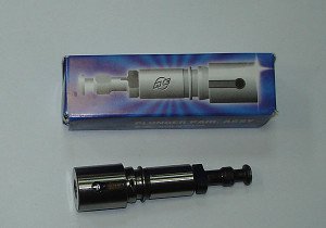
The main element of the injection pump is a plunger pair. It is a long piston of a small diameter (as a rule, the diameter of the device is several times less than its length), which is fitted as closely as possible to the working cylinder. The gap between them (it is called precision mating) never exceeds 1-3 microns. The working cylinder contains intake valves (two or one) through which fuel is supplied. Then it is pushed out by a plunger through the outlet valve.
Pumps are structurally divided into three types:
- distribution: 1 or 2 plungers are installed in it, which inject fuel and distribute them over the existing cylinders;
- in-line: has a separate plunger pair;
- trunk: they are responsible for pumping fuel into the accumulator.

