In detail: do-it-yourself tractor engine repair from a real master for the site my.housecope.com.
Everything about the MTZ-82 tractor: device, operation, repair, technical characteristics and repair. D-240 engine: MTZ engine repair.
 "D-240 engine" Overhaul of the D-240 engine of the MTZ-82 tractor. Complete assembly and disassembly
Cylinder head repair
The main defects of the cylinder head (cylinder head) are: wear of the inner surfaces of the guide bushings, valve seats and working chamfers; buckling of the connector plane; burnout of seats for seals of glasses or nozzles; cracks in the bridges of the valve seats.
During the technical examination, they are guided by the basic values and adjusting data of the parts of the cylinder head d-240 and the gas distribution mechanism.
The main adjusting data and indicators of the gas distribution mechanism and the cylinder head of the MTZ-82 engine
The sinking of the valve poppets in the head seats can be determined without dismantling it from the cylinder block by measuring the protrusion of the suction valve rods relative to the head surface. To do this, it is necessary to set the pistons in turn at the top dead center of the compression stroke and measure the distance from the end of the valve stem to the head. If the valve protrudes by an unacceptable amount, then this indicates that the valve poppets and their seats are worn out.
The location of the cylinder head parts: 1 - branch pipe; 2 - pipe; 3 - breather body; 4 - tank; 5 - cap; 6, 8 - gaskets; 7 - head cover; 9 - rocker; 10 - axis; 11 - cylinder head; 12 - head gasket; 13 - pusher; 14 - barbell; 15 - outlet valve; 16 - inlet valve; 17 - valve springs; 18 - valve plate; 19 - hairpin.
| Video (click to play). |
You can also set the degree of development of the camshaft cams. To do this, turn the engine crankshaft until the valve is fully open (with the thermal clearance set for a cold engine) and measure the distance from the end of the valve stem to the head. The movement of each valve can be determined by the difference in distance measured with the valves fully open and closed. If the valve movement is below the required value, then the camshaft should be replaced.
Measurement of the flatness deviation of the cylinder head surface: 1 - straight edge; 2 - cylinder head; 3 - probe.
At the end of all measurements, remove the head from the engine and continue further inspection. Measure the flatness deviation of the head surface. If the deviation from flatness is exceeded, the head must be replaced; if the deviation is in the range of the permissible rate, then check the condition of the valve seats by sinking the new valve disc. If the valve disc sinks into unacceptable values, the head is replaced; if everything is normal, then disassemble and repair the head.
Drowning Saucer Definition: 1 - valve; 2 - cylinder head; 3 - barbell depth gauge.
Removing valve cuts and valve springs: 1 - cylinder head; 2 - valve spring; 3 - device OR-9913.
The valve springs and valve crackers are removed using a special device OP-9913. If there are cracks in the valve seat, replace the head. The dismantled valves are marked, and then the diameter of the circumference of the rod is measured and the bending of the rod and the beating of the valve disc are checked.
Measuring the diameter of the valve stem: 1 - valve; 2 - micrometer.
Stem Bend and Poppet Chamfer Runout Measurement
The bend of the rod relative to the valve axis and the bend of the chamfer should not be more than 0.03 mm.In the presence of traces of burnouts, wear, cavities on the valve chamfers, the working surface of the chamfers is ground on R-108 or OP-6686 machines. The intake valve is ground at 60 degrees and the exhaust chamfer is grinded at 45 degrees. After detecting traces of wear and tear, the width of the cylindrical part of the valve disc A, and the width of the ground-in matte strip on the chamfer of valve B should be no more than 2 mm.
Grinding the valve chamfer face
Measuring the bore diameter of the valve sleeve: 1 - indicator bore gauge; 2 - guide sleeve; 3 - cylinder head.
Pressing out the guide bush
Pressing in the valve guide: 1 - guide sleeve; 2 - valve; 3 - cylinder head.
Valve seat machining in cylinder head
The valve guide is replaced when the surface of the valve stem bore is depleted to an unacceptable diameter value or when the bushing is loose in the head. Before replacing, the guide sleeve must be pressed out. The new bushing is selected with the largest outer diameter tolerance and lubricated with epoxy glue without filler, and then pressed into the head using a special bolt.
As soon as the guide sleeves are installed, it is necessary to process the valve seat with a grinding device OPR-1334A. If there are burn-throughs, scratches and cavities on the working chamfer of the seat, the initial chamfer should be ground until defects are removed and the seat should be checked for sinking of the new valve disc. The upper edge of the working chamfer of the seat in the cylinder head is machined with a grinding wheel with a cone angle of 60 degrees, and the lower one - 150 degrees. The width of the working chamfer of the seat for exhaust valves should be 1.5-2.0 mm, and for intake valves - 2.0-2.5 mm.
After machining, the valve seat and disc must be rubbed in. During the repair of 1-2 valves, lapping is carried out with a 2213 pneumatic device, using a paste from a mixture of M20 micropowder with engine or industrial oil.
During lapping, the valve is lifted and rotated from time to time. Periodically inspect the condition of the lapping chamfers of the valve and seat. The upper edge of the matte strip of the working chamfer should be located at a distance of at least 0.5 mm from the cylindrical part of the valve disc. When a matte strip is found significantly above or below this distance, the saddle is again processed with grinding wheels and lapped.
Before assembling the valves, check the compression force and length of the valve springs on the MIP-100 device. In case of invalid parameters of the springs, they must be replaced. Sometimes, to compensate for the compression force and the length of the springs, washers are placed under them, the thickness of which can be calculated by the formula:
- for the exhaust valve A = B-1.8 mm, where B is the sinking of the valve, measured after repair of the seat;
- for inlet - A = B-1.3 mm.
When assembling the valve, make sure that the protrusion of the crackers above the plane of the spring plate is no more than 0.5 mm, the sinking does not exceed 1.3 mm. In order to check the valve for leaks, the exhaust and inlet channels of the cylinder head must be filled with kerosene, which should not flow for one and a half minutes.
Before installing the rocker arm axles, check their technical condition. If grooves exceeding 0.3 mm are found on the rocker arm strikers, the surface of the striker should be sanded until the defects are corrected. A deviation from the parallelism of the working surface of the rocker arm is allowed no more than 0.05 mm. If necessary, check the bore diameters of the rocker arm bushings. The gap between the axis of the rocker arms and the bushing should be no more than 0.15 mm.
At the stage of operation of the life cycle of an engine (unit), in addition to current and overhaul repairs, technical condition repairs, warranty and preventive repairs can be performed.
Technical condition repair is carried out according to the results of assessing the technical condition of the machine (unit) according to a number of estimated indicators in the event that the values of these indicators differ from the permissible ones. Depending on the number of such indicators, the volume of repair actions is established. This type of repair allows you to maintain and even increase the resource of a machine or its units and can be performed at specialized repair plants and other large repair enterprises.
Warranty repair is carried out in order to eliminate failures that occur in the warranty operating time interval and through the fault of the manufacturer (overhaul plant).
Preventive repair is carried out according to the recommendations of the chief designer in order to replace the elements that do not provide the specified overhaul life of the product. As a rule, such repairs are carried out by the repair services of the organizations operating the product. Replacement elements (spare parts) are supplied by the manufacturer.
Repair methods determine the organizational forms of predominantly assembly processes when restoring a machine (unit).
On the basis of the preservation of the belonging of the repaired parts to a machine or unit, repairs can be carried out by non-personalized and impersonal methods.
At non-impersonal repair method defective units and parts are removed from the machine, repaired and installed on the same machine. At the same time, the mutual wearing-in of the parts, their initial interconnection, is preserved, due to which the quality of the repair is, as a rule, higher than with the impersonal method. Significant disadvantages of the non-impersonal repair method are that it significantly complicates the organization of repair work and inevitably increases the duration of the product being repaired.
An impersonal method - a method of repair, which does not preserve the belonging of the restored components to a specific instance. The units and units removed from the engines are replaced with previously repaired or new ones taken from the circulating fund, and the faulty units and units are repaired and replenish the revolving fund. With an impersonal repair method, the organization of repair work is simplified and the duration of the product's stay in repair is significantly reduced. Saving time is achieved due to the fact that the objects of repair do not wait until the units and assemblies removed from them are repaired.
According to the organization of the execution, the repair of machines can be carried out by the aggregate method, which is an impersonal repair, in which faulty units are replaced with new ones or previously repaired (from the circulating fund). In this case, the removed faulty units are sent for repair to specialized repair companies.
Aggregate method is the main method of repairing machines and allows you to reduce the duration of repairs, to restore a significant number of machines in a short time. The aggregate method of repair requires a working fund, the value of which depends on the capacity of the repair company, the time spent on exchanging faulty units and the machine as a whole, and the safety stock of units.
Depending on the type of production (mass, serial, single), engine repair can be organized by the flow method, by the method of specialized posts (brigade-nodal) or universal posts (dead-end).
Stream method characterized by the location of technical equipment in the sequence of operations of the technological process and the specialization of workplaces.
A machine, units, mechanisms, parts (for example, a cylinder block, an engine crankshaft) are transferred from one specialized post to another immediately after the next technological operation.The in-line method provides high labor productivity, effective use of high-performance specialized equipment, and creates conditions for achieving high rates of repair quality.
Specialized post method characterized by the fact that repair work, for example, disassembly and assembly of units and assemblies, as well as work on the restoration of parts and repair of assembly units, are carried out by teams (performers) specializing in car brands, assembly units of a certain type.
The specialization of posts (teams, performers) can be technological in performing certain operations and detailed. The method of specialized posts is used at repair enterprises that carry out medium repair of engines on finished units.
Method of universal posts characterized by the fact that all work on engine repairs is performed at one working position by one team. At the same time, labor productivity and the utilization rate of equipment are low. The qualifications of the workers must be high, since the members of the team have to perform different types of work.
In general, repairs can be scheduled. Setting the engine for such repairs is carried out in accordance with the requirements of the normative and technical documentation. The engine is put up for unscheduled repairs without prior appointment. Medium and major repairs are carried out according to the planned operating time.
Planned repairs, performed with the frequency and in the amount established by the operational documentation without taking into account the technical condition of the machine at the time of the start of the repair, is called regulated.
Technical condition repair - scheduled repairs, in which the technical condition is monitored at the frequency established in the normative and technical documentation, and the volume of repairs and the start of work are determined by the technical condition of the product.
Purpose of engine repair - this is the restoration of the operational characteristics and parameters of the engine or a separate unit, part to the level specified in the data sheets, instructions for use and repair. The performance and parameters of the engine, which are monitored and determine the quality of the repair, include engine noise; smoke and toxicity of exhaust gases; starting characteristics: vibration level, stability of operation in all modes; acceleration, power (torque), operating fuel consumption; engine life after repair, i.e. mileage until the next repair.
Tools and equipment for engine repair. The main tools for repairing engines are socket wrenches, commonly referred to as socket wrenches. The heads can have different lengths, the dimensions of the square hole for the wrench, and the shape of the working part (six-, twelve-sided and hexagonal star type).
Torque wrenches are used for calibrated tightening of bolts (nuts). Most often, two types of such keys are used - with a continuous reading of the moment on a scale and adjustment on a scale, and indication of a given moment by a characteristic click.
To speed up the tightening of a large number of bolts and nuts of the same type, for example, the oil pan, cylinder head, manifolds and other elements, a pneumatic tool is used.
When repairing engines, in addition to a universal tool, it is necessary to have a fairly large range of special devices, without which many operations are difficult to perform.
Defect detection of parts. To assess the technical condition of parts with their subsequent sorting into serviceability groups in the repair production, a technological process called flaw detection is defined.In the hall of this process, the compliance of parts with the technical requirements, which are set out in the technical conditions for repairs or in the repair manuals, is checked, while a complete control of the parts is carried out. To exclude non-recoverable parts, the following stages of defect detection are used: with obvious irreparable defects - visual inspection; with hidden fatal defects - non-destructive testing; with irreparable geometric parameters - measuring control.
In the process of flaw detection of parts, the following control methods are used: organoleptic examination (external condition of the part, presence of deformations, cracks, scoring, chips, etc.); instrumental check using devices and devices (revealing hidden defects of parts using non-destructive testing tools); non-scale measures (calibers and levels) and micrometric instruments (rulers, vernier tools, micrometers, etc.) to assess the size, shape and location of surfaces of parts. In the process of flaw detection, only those elements of the part that are damaged or worn out during operation are subject to inspection.
First of all, you need to check the gaps in the main mates. For most new engines, for their normal operation, the clearance between the piston and the cylinder should be 0.025 ... 0.045 mm, and the limiting clearance should not exceed 0.2 mm.
As a result of the control, the parts should be subdivided into three groups: suitable parts, the nature and wear of which are within the limits allowed by the technical conditions (parts of this group are used without repair); parts to be restored, defects of these parts can be eliminated by the methods of repair mastered at the repair enterprise; unusable parts. [Basics of operation and repair of cars and tractors. Ed. S.P.Bazhenov. 2005]
Tractors have been successfully used for more than half a century in agriculture, housing and communal services, construction, forestry enterprises. In the post-Soviet space, the most common of them are the MTZ-80 and MTZ-82 tractors, which are manufactured by the Minsk Tractor Plant. The increased demand is caused not only by the high power, functionality and performance, but also by the durability of the devices.
However, these machines sometimes fail and require repairs. Simple tasks of restoring the operability of these tractors can be solved with your own hands.
Maintenance and repair of tractors are mandatory procedures that every owner of universal wheeled vehicles has to face. Before proceeding with the practical part, you need to familiarize yourself with the device, the main units of MTZ-80 and MTZ-82. On these models, the manufacturer installs 4-cylinder diesel engines of the 4CH11-12.5 series, produced by the Minsk plant. The engines have semi-divided liquid-cooled combustion chambers made in the piston.
Parts of the internal combustion engine were equipped with a pre-heater. The working volume of the power plant is 4.75 liters, and the rated power is 80 hp. The motor is started by an electric starter. Mechanical transmission with 22 gears (18 forward and 4 reverse). The clutch is single-disk, dry, closed. The 9-speed gearbox is equipped with a reduction gear. The rear axle has a differential with a locking function.
Tractors are characterized by: rigid rear wheel suspension, semi-rigid suspension with a balanced front wheel axle, disc brakes, power steering MTZ. The hydraulics include: an NSh-32 pump driven by the engine, a hydraulic cylinder for controlling a mounted plow, a slide-valve hydraulic distribution. The MTZ-80 model has a rear-wheel drive and a small cab. MTZ-82 is an all-wheel drive vehicle.
to the menu ↑
Maintenance of the MTZ-80 and MTZ-82 tractors has a planned preventive nature.It is produced with the aim of maintaining equipment in a working, serviceable condition, increasing efficiency, reliability, and extending the service life. A maintenance system has been installed for the machines. It includes 3 numbered and periodic maintenance, labeled under No. 1,2 and 3. As additional maintenance, seasonal operations are carried out.
- the first maintenance is carried out every 60 hours of operation;
- the second - every 240 hours of operation;
- the third - every 960 hours of operation.
In between shifts, monthly maintenance is performed, which is 10 hours of work. In this case, the following actions are carried out:
-
- Check for oil, fuel, electrolyte and water leakage.
- The filtered fuel is added to the diesel and starting engine tank.
- Measure the oil level in the crankcase, check the water level in the radiator.
- The condensate is drained from the receiver.
- Check the degree of clogging of the air cleaner.
Numbered TO provide for the above stages and specific ones. Seasonal ones are required when switching to autumn-winter period from spring-summer and vice versa.
Do-it-yourself current repair of MTZ-80 and its “successor” MTZ-82 provides, first of all, the removal of faulty assemblies and parts with their subsequent replacement with repaired or new ones.
Disconnecting the rear axle of the Belarus tractor
When carrying out this procedure, one should be guided by the following principles:
- disassembly of the tractor or its assembly unit is carried out within the limits necessary to identify the cause of the malfunction and its elimination;
- it is necessary to remove the unit only if it is not possible to eliminate the malfunction in another way.
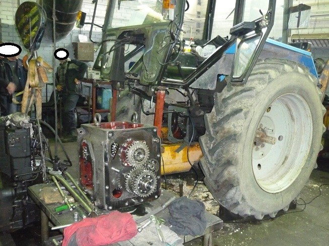
For the MTZ-80, MTZ-82 models, parts and assemblies are mounted on a semi-frame frame, consisting of a front half-frame. The latter is used to install the internal combustion engine. Dismantling of tractors begins with disconnecting the frame, removing the units. Dismantling requires the use of: a manual or electric hoist, a crane-beam and other devices. When repairing tractors, pay special attention to the assembly sequence with subsequent adjustment of parts, assemblies and drives. If current repairs can be carried out at home, (both outdoors and in a special room), then to carry out a major overhaul, you will have to contact a specialized center that has instrumentation and equipment for this.
Defect detection of working elements is carried out after flushing in order to detect the presence of wear, cracks, chips, scratches on their surfaces. After examining the worn parts, their dimensions and shapes are checked, for which a measuring tool is used. To establish the possibility of carrying out repairs, the interaction of the unit with the associated part is checked, more often by replacement. Replacement takes place when the dimensions of the part, as a result of wear, interfere with the operability of the mechanism.
The design of the tractors allows some parts to be replaced without preliminary dismantling, namely: an air cleaner, a generator, a centrifugal oil cleaner, a starter, a fuel pump, a hydraulic distributor mechanism, a power take-off shaft, an intermediate support for a propeller shaft, a compressor, a transfer case.
to the menu ↑
To repair the transmission, disconnect the frame of the machine. The tractor is rolled out on planes according to the scheme: clutch housing - MTZ-80/82 gearbox - rear axle. Install a fixed jack stand under the rear axle, movable ones are placed under the clutch housing and gearbox. Then they disconnect, roll out the skeleton, remove the box.
In the event that malfunctions were detected when turning on / off the first gear, reverse gear, then it is necessary to remove the side cover and the shift fork. The last part requires replacement when the gap is more than 1.5 mm. Determine the size of the gap by alternately connecting the fork to the slots of the sliding carriages. The gear block is changed when the groove width exceeds 10.8 mm.
When there are extraneous noises in the gearbox, excessive heating of the housing is noticed, this indicates a seizure or destruction of the shaft bearings. To fix the problem, drain the oil from the MTZ gearbox. Use a crowbar to turn all the shafts accessible for inspection. They need to be influenced in the radial and axial directions. Bearing races must not rotate in their seats. If it is found: movement of the shafts, wear of the bearings, the gearbox is removed from the tractor, disassembled with the replacement of faulty bearings.
Gearbox repairs can be triggered by knocks that disappear when shifting to the next gear. In this case, problems arise in the gear teeth. Check for wear by jacking one of the drive wheels, spinning it and inspecting the teeth of the visible gears. If the defect is visible with the naked eye, the parts are replaced.
to the menu ↑
to the menu ↑
The internal combustion engine is removed assembled from the tractor when cracks, knocking of connecting rod or main bearings are detected in the cylinder block. First, the crankshaft journals and connecting rod bearings are tested for functionality. It is necessary to remove the oil pan, oil pump, oil lines, connecting rod caps. Measure the diameter of the crankshaft journals in 2 planes - perpendicular and parallel to the longitudinal axis of the connecting rod. With a decrease / increase in diameter, the crankshaft is removed and given for regrinding.
To find out whether it is worth replacing the connecting rod bearings of the MTZ-80, MTZ-82 engine, measure the size of the connecting rod bearing bore. In this case, its cover must be tightened. The design clearance ranges from 0.05 to 0.12 mm, and the excess of the allowable clearance is limited to 0.3 mm.
D 242 engine after overhaul
On MTZ-80 tractors, special attention will be paid to engine repair. If the oil level rises in the diesel engine crankcase, it means that as a result of the formation of cracks, the tightness of the liner seals is broken. It is possible that water has entered the cylinder block from the cooling system. A high pressure reading or a low reading indicates a malfunction with the oil pump, misalignment, worn bypass and drain valves, or a faulty thermostat valve. Check the oil pressure, if the indicator is below 0.08 MPa, stop the engine, adjust the drain valve, wash the filter parts.
to the menu ↑
Repair of electrical equipment is carried out in case of malfunctions of the generator and starter. The generator is checked by turning on the electricity consumers, setting the crankshaft rotation speed corresponding to the nominal one. After connecting to a voltammeter and smoothly increasing the current to 30 A, measure the voltage (the permissible value is not less than 12.5 V). The difference between the generator voltage and the nominal makes it necessary to replace the part.
Pre-check the main elements for a malfunction with a warning lamp. Remove the back cover and the EUT, release the coil leads from the panel bolts. At the end of these steps, proceed to check for a short circuit between the generator case and the windings of the tractor electrical equipment. Defects in insulation and diodes lead to replacement.
Installing the battery on MTZ over the rear axle
The starter is examined using KI-1093, a portable device. Remove the wire from the storage battery leading to the starter, put on the “+” terminal a volt-ammeter connected to the KI-1093. Put in top gear. After making sure that no fuel is flowing, turn on the starter for 7-10 seconds. to monitor the readings of measuring instruments.
A small voltage indicator indicates a discharged or malfunctioning AB, oxidation of the clamps. An increased value of the current that the starter consumes indicates an interturn short circuit of the armature windings. If you notice the rotation of the armature during the check, look for a malfunction in the clutch mechanism. In all these cases, it is advisable to replace the starter with a new one.
The main malfunctions of the D-240 diesel
The technical condition of individual systems and mechanisms of the D-240 diesel engine of the MTZ-80 tractor is determined by external and indirect signs, as well as using diagnostic tools.
A decrease in the power of a diesel engine, excessive consumption of crankcase oil, the appearance of a large amount of gases coming out of the breather indicate wear of the cylinder-piston group, coking (sticking) of the piston rings.
Difficulty starting a diesel engine, interruptions during operation at the minimum crankshaft speed, the appearance of black smoke from the exhaust pipe indicate malfunctions of the fuel equipment, contaminated fuel filters, low pressure in the system, loose fit, burnout of valve seats and valve plates.
The degree of contamination of the filter elements for fine fuel purification and the maximum pressure developed by the fuel priming pump are checked with the KI-13943 device.
The drop in the power of the D-240 engine of the MTZ-80 tractor, a decrease in the crankshaft rotation speed are also affected by contamination of the air cleaner, leaks in the air intake duct connections, violation of the adjustment of the regulator control lever.
The degree of contamination of the air cleaner elements is determined by the signaling device, the sensor of which is installed in the intake manifold of the diesel engine.
The appearance of a red stripe in the inspection window of the warning device (or the illumination of a warning light on the cab instrument panel for tractors manufactured since 1989) during diesel operation indicates the need to clean the air cleaner.
The tightness of the intake air duct is checked at an average diesel crankshaft speed by blocking the central pipe of the air cleaner.
In this case, the diesel engine must stop quickly. Otherwise, use the indicator. KI-13948 identify leaks in the intake tract and eliminate the malfunction. The indicator pressure should not exceed 0.08 MPa.
If the speed of the crankshaft of the D-240 engine, determined by the tachospeedometer, or the speed of the power take-off shaft does not correspond to the nominal values, you should pay attention to the adjustment of the regulator thrust.
When the pedal is fully depressed or the fuel control handle is set to the "Full" position, the outer regulator lever must rest against the maximum speed limiter bolt.
Excessive consumption (waste) of crankcase oil or a large amount of gases coming out of the breather, the appearance of blue smoke from the exhaust pipe indicate the extreme wear of the cylinder-piston group.
To assess the technical condition of the cylinder-piston group, a method is used to determine the amount of gases breaking through into the diesel crankcase. This parameter is measured using a KI-4887 gas flow meter.
During the operation of MTZ-80 tractors, there are cases when not all cylinders fail. This can be caused by coking ("sticking") or breakage of the piston rings, which inevitably leads to scuffing of the working surface of the cylinder liner.
A comparative assessment of the technical condition of each cylinder is carried out by measuring the pressure at the end of the compression (compression) stroke at the starting speed of the crankshaft using the KI-861 compressor (Fig. 2.1.3).
Rice. 2.1.3. Checking the compression in the cylinders of the D-240 diesel
1 - compressor KI-861; 2 - mounting plate
The minimum pressure at the end of the compression stroke for a new engine should be 2.6-2.8 MPa; the pressure of the extremely worn one is 1.3-1.8 MPa. The most accurate reading is obtained by determining the difference in compression values for each cylinder.
If the difference between the compression of an individual cylinder and the average compression value in the remaining cylinders exceeds 0.2 MPa, then this indicates a malfunction of this cylinder.
The decrease in pressure at the end of the compression stroke in individual cylinders is affected by the violation of the tightness of the valve-seat interface. Loose fit of the valves to the seats is possible due to a violation of the clearance adjustment in the valve drive.
In the absence of a gap between the valve and the rocker arm during the working stroke of the piston, gases break through the leaks and destroy the surface of the working chamfers of the valve and its seat; as a result, the compression in the cylinder is reduced and the start of the diesel engine is more difficult.
The release of coolant from the radiator, especially with an increase in the load on the diesel engine, indicates a breakdown of the cylinder head gasket, a weakening of the tightening of the nozzle glass, and the appearance of cracks in the cylinder head.
If it is not possible to eliminate the defect by tightening the cylinder head mounting bolts or injector cup nuts, then the head is removed and inspected.
An increase in the oil level in the diesel engine crankcase indicates a violation of the tightness of the liner seals with the block as a result of cracks, cavitation destruction of the metal of the cylinder block, the ingress of water from the cooling system into it and other factors.
Low or high oil pressure (gauge) and temperature (remote thermometer) indicate low oil pump flow, wear or misalignment of the drain and bypass valves, excessive wear on the crank joints, malfunction of the thermostat valve in the cooling system, poor oil quality , contamination of the centrifugal oil cleaner.
If the oil pressure in the lubrication system according to the pressure gauge is below 0.08 MPa, the engine is stopped, the reasons for the pressure drop are found out and eliminated, the drain valve of the centrifugal oil filter is readjusted by tightening its spring, and the filter parts are washed.
If the pressure does not increase as a result, the pressure in the diesel lubrication system is measured with the KI-13936 device (Fig. 2.1.4) at the nominal crankshaft speed and, according to its readings, it is judged that the diesel engine needs to be repaired.
Rice. 2.1.4. Measurement of oil pressure in the engine smear system D-240
1 - device KI-13936; 2 - centrifugal oil filter
The appearance of extraneous noise and knocking during the operation of the motor indicates an increased or extreme wear of the mates of its parts.
Upon reaching the limiting clearances in the mating of parts, as a result of wear, dynamic loads and accompanying knocks appear, which are heard by a stethoscope in certain zones and under the appropriate operating modes of the diesel engine.
The sound of a dull middle tone in the piston movement zone, first at minimum and then at maximum speed, indicates an increased clearance between the piston and the liner.
A strong ringing sound of a metallic tone under the same test conditions indicates the ultimate
wear or melting of the connecting rod bearing.
A more dull sound of a low tone, periodically heard in the area of the main journals of the crankshaft at the rated speed with a periodic increase to the maximum, indicates wear of the main bearing shells.
The ringing sounds of a high-pitched metal tone, constantly audible at any crankshaft speed and intensifying when the diesel engine warms up, indicates increased thermal clearances in the valve train.
With an increased thermal gap, the degree of filling the cylinder with air and cleaning it from exhaust gases decreases, which affects the power of the diesel engine.
The thermal clearance in the valve train is checked with a feeler gauge with the valves fully closed at the end of the compression stroke. On a "cold" D-240 engine, the gap should be within 0.40-0.45 mm.
Dull sounds heard on the block on the right side when the diesel engine is running at low revs indicate large gaps in the camshaft bushings.
Knocking under the camshaft cover when the crankshaft speed changes abruptly indicate significant wear on the camshaft teeth.
If the parameters of the technical condition of the diesel engine have reached their limit values or exceed the permissible values in operation, then the diesel engine is disassembled for a technical examination-inspection, micrometering of the couplings of the cylinder-piston group and the crank mechanism, replacement of parts.
Dismantling the diesel engine D-240
The assembled diesel engine (Fig. 2.1.6) is removed from the tractor and replaced with a new one or repaired in case of cracks in the cylinder block, emergency knocks of main or connecting rod bearings, the limiting value of the clearance in at least one interface between the crankshaft journal and the liner.
Rice. 2.1.6. Diesel engine D-240 of the MTZ-80 tractor assembled
1 - oil pan; 2 - crankshaft; 3 - connecting rod; 4 - flywheel; 5 - a camshaft; 6 - cylinder block; 7 - cylinder head; 8 - cylinder head cover; 9 - cap; 10 - valve; 11 - valve spring; 12 - piston; 13 - barbell; 14 - fan
The type of repair - major or current - is determined when measuring the main parts of a diesel engine: piston pins, pistons, cylinder liners, connecting rod bushings. First of all, check the condition of the connecting rod bearings and crankshaft journals.
To do this, remove the oil pan, oil lines, oil pump, connecting rod caps, measure the diameter of the crankshaft connecting rod journals (Fig. 2.1.8).
The diameter of the connecting rod journals is measured in two planes - parallel and perpendicular to the longitudinal axis of the connecting rod.
If the ovality of the journals exceeds the permissible size or their diameter is less than the lower tolerance of the corresponding size group, then the crankshaft must be removed (Fig. 2.1.10) and reground to the next repair size.
Rice. 2.1.8. Measurement of the diameter of the connecting rod journals of the D-240 crankshaft
1 - micrometer; 2 - connecting rod journal of the crankshaft
Rice. 2.1.10. Removing the rear crankshaft support
1 - back support; 2 - bolts of the rear support
Nominal and repair dimensions of the connecting rod journals of the D-240 diesel engine of the MTZ-80 tractor
Size group designation / Size size, mm
H1 - 68.16-68.17
H2 - 67.91-67.92
D1 - 67.66-67.67
P1 - 67.41-67.42
D2 - 67.16-67.17
P2 - 66.91-66.92
DZ - 66.66-66.67
RZ - 66.41-66.42
In practice, in addition to overhaul dimensions (P1, P2, P3), alternating every 0.5 mm and determined by the diesel engine manufacturer, with slight wear of the crankshaft journal, they are ground to additional dimensions (D1, D2, DZ), alternating with overhaul dimensions through 0.25 mm.
In the same way, the inserts of repair sizes are bored for additional sizes (D1, D2, DZ). The ovality of the connecting rod journals of the D-240 diesel is allowed no more than 0.06 mm.
If the dimensions of the connecting rod journals are within the normal range, the disassembly of the motor is continued (Fig. 2.1.11-2.1.14), the cylinder head is removed and the pistons with connecting rods are removed.
To decide whether it is necessary to replace the connecting rod bearing shells, measure the diameter of the connecting rod bearing bore with its cap assembly with shells tightened.
Rice. 2.1.11. Removing the cylinder head cover
Rice. 2.1.12. Removing the cylinder head cover D-240 of the MTZ-80 tractor
Rice. 2.1.14. Removing the cylinder head
The difference between the measurements of the diameters of the crankshaft connecting rod journal and the connecting rod bearing bore gives the actual diametral clearance in the connecting rod bearing. The nominal clearance in the connecting rod bearings corresponds to 0.05-0.12 mm, the allowable clearance is no more than 0.3 mm.
In cases where the surface of the bushings is in a satisfactory condition, the only criterion for the need to replace them is the size of the diametrical clearance in the bearing.
When assessing the condition of the liners by inspection, it should be borne in mind that the surface of the antifriction layer is considered satisfactory if there are no scuffing, chipping of antifriction material and inclusions of foreign materials on it.
Seals of the crankshaft of the D-240 engine of the MTZ-80 tractor
To replace the cuff of the rear crankshaft seal, first remove the clutch and flywheel (Fig. 2.1.48, 2.1.49).
After removing the crankshaft seal housing from the side of the rear sheet (Fig. 2.1.50), press out the cuff with a stepped mandrel. When replacing the cuff of the front crankshaft seal, remove the front cover of the diesel engine.
Rice. 2.1.48.Unscrewing the flywheel mounting bolts D-240
Rice. 2.1.49. Pressing the flywheel
1 - back sheet; 2 - three-blade stripper; 3 - flywheel
Rice. 2.1.50. Removing the crankshaft seal housing
| Video (click to play). |
1 - seal housing; 2 - diesel back sheet; 3 - bolt

