In detail: do-it-yourself repair of a tractor generator 3701 from a real master for the site my.housecope.com.
What if you find that the ammeter displays the discharge current at the rated engine speed? We check the tension of the alternator belt. If the tension is normal, we look for an open wire in the power supply circuit of the excitation winding. If they are in order, the contacts of the connecting wires must have acidified.
By the way, with turn-to-turn closure or breakage of turns in the excitation winding, short-circuit of the stator winding to the case, with the breakdown of diodes of reverse or direct polarity of the rectifier, the same situation arises.
Why might there be a large charging current? A short circuit of the battery plates is quite likely, and this leads to a decrease in the internal resistance of the battery and an increase in current.
Noise and knocking in the generator can occur due to the weakening of the fastening of the generator drive pulley, the destruction of bearings or the development of their seats. So the noise is obtained due to the grazing of the rotor on the stator.
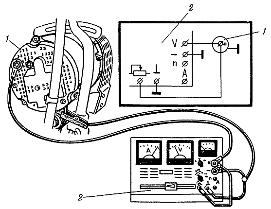
How to check the operation of the 464.3701 generator on a tractor? We connect electricity consumers, bring the engine crankshaft speed to the nominal one, measure the voltage with a KI-1093 voltammeter between "+" and the unpainted place of the generator case (Fig. 2.2.1) and, smoothly adding the load current to 30 A, measure the voltage. It must be at least 12.5 V.
Rice. 2.2.1. Scheme for checking the generator output voltage under load on the MTZ-80, MTZ-82 tractor:
1 - generator; 2 - voltammeter KI-1003
What to do if the generator voltage is very different from the nominal or not at all when the battery is disconnected? The generator must be removed for inspection and possibly subsequent replacement. How to check the MTZ-80, MTZ-82 generator? First, you need to check the serviceability of the main elements of the generator using a 12 V warning lamp.
| Video (click to play). |
The sequence of actions is as follows: remove the back plastic cover and an integrated device (IU); then we release the leads of the excitation coil and the additional rectifier from the bolts of the terminal panel. We check the absence of a short circuit in the diodes or between the windings and the generator case (see Fig. 2.2.2).
Rice. 2.2.2. Schemes for checking the generator for the absence of a short circuit MTZ-80, MTZ-82
a - how to check the diodes of the rectifier unit; b - how to check the stator windings and reverse polarity diodes; c - how to check diodes of direct polarity; d - how to check the diodes of the additional rectifier; e - how to check the field windings on the generator case;
1 - generator case; 2 - terminal "+"; 3 - terminal "Ш"; 4 - outputs of the phases of the rectifier unit; 5 - storage battery; 6 - terminal "D"; 7 - terminal of the output of the end of the excitation winding; 8 - output terminal of the beginning of the excitation winding; 9 - control lamp
In the event of a short circuit of diodes, winding or breakdown to the case, the control lamp lights up. That is how it should be. If the insulation of the windings is broken and the diodes are faulty, the generator must be changed. The generator is calibrated on the KI-968 or 532M test benches.
First of all, the voltage of the generator without load is checked. It must be at least 12.5 V at a rotor speed of no more than 1400 rpm. Next, the voltage of the generator is checked under load, with a load current of 36 A and a rotor speed of 3000 rpm. It must also be at least 12.5 V.
To check the integral device, the load current is reduced to 5 A, and the rotor speed is tried to be kept within 3000 rpm.In the "summer mode" (the seasonal adjustment switch in the "L" position), the voltage on the generator should be 13.2-14.1 V. In the "winter mode" (the seasonal adjustment switch in the "W" position), the voltage is slightly higher, within 14.3-15.2 V. If these parameters do not correspond, the integrated device must be replaced.
- SHOW FULL PRICE LIST
MTZ
MMZ
MAZ
The MTZ generator is a current source that ensures the operation of all electrical appliances of the tractor.
BelMAZdizel LLC will tell you about what the generator consists of and how to repair the mechanism.
There are two types of mechanisms - direct and alternating currents. The MTZ generator of the first type consists of:
- Winding anchors;
- Inductors;
- Diodes;
- Collectors.
Power is generated in the wound cores. When equipment moves, magnetic fluxes increase. A diode with a semiconductor is a rectifier. The constant voltage generation by the tractor generator is regulated by a special automatic system.
The current is conducted in one direction only. Generators of the second type of tractor are capable of operating without voltage regulators. A rectifier is required to charge the battery.
Consists generator MTZ alternating current from the following elements:
- Stator;
- Rotor;
- Back and front covers;
- Bearings.
There are six cores in the tractor generator body. The elements are made of iron plates. The copper winding is fixed to the core. Each has 63 turns. The ends of the winding are connected to the terminals.
The MTZ generator has a switch. A wire and terminals are connected to it. To ensure the normal operation of the tractor generator, it is necessary to connect lamps of a suitable power. The mechanism has three working positions.
The discharge current at the rated shaft speed indicates a weak tension in the belt of the MTZ generator. Broken wires or oxidation of the terminals could also have occurred. The discharge current occurs due to turn-to-turn short circuit and breakdown of rectifier diodes. If knocks and noises appear in the MTZ generator, it is necessary to tighten the nuts of the wire pulley.
Extraneous sounds can also occur as a result of wear or destruction of ball bearings. The rotor touches the stator. Urgent repair of the generator 82 is required. A high charging current indicates a battery malfunction.
However, before attempting to repair generator 82, a check must be done. All consumers of electricity are switched on on the tractor. Set the rated shaft rotation power and connect a voltammeter.
Gradually increase the load on the tractor generator and measure the voltage. The value of the measured parameter should not be less than 12.5 V. If the voltage differs significantly from the set one, repair the generator 82.
The serviceability of the elements is checked with a control lamp. You need to remove the back cover and the integral device. Release the coil leads and check for a short circuit in the tractor generator.
When a malfunction is detected, the control lamp lights up. If the winding insulation is broken or diodes are out of order, the MTZ generator must be replaced.
Dirt on the collector and brushes can cause a malfunction.
To ensure stable operation, the tractor generator needs to be cleaned regularly. Elements with wires are wiped with a rag soaked in gasoline. Then the parts are purged and dried.
The rest of the MTZ parts are washed in a special solution. It is allowed to use ordinary kerosene. To repair the generator 82, it must be disassembled.
If you need to replace the pulley, bend the washer and unscrew the nut.
Then remove the mechanism with a puller. To replace the rectifier unit, the tractor generator is unscrewed. Remove the cover and disconnect the wires from the terminals. Release the stator leads and twist the washers.
The rectifier unit must be removed when repairing the generator 82 when replacing the stator or bearing.
General information.Generator 46.3701 is intended for tractors and self-propelled agricultural machines. Its power is 0.7 kW, and it is made with a built-in voltage regulator.
The presence of a powerful power source on the tractor allows you to solve a number of tasks to improve the working conditions of the tractor driver and increase the productivity of labor.
The 46.3701 generator has several modifications that differ in the size of the drive pulley. So, for example, the generator of modification 54.3701 is installed instead of the generator G306.
On the unified generator, in addition to the main rectifier, there is an additional one (terminal D), with the help of which the battery is prevented from discharging to the excitation winding of the generator when parked, and the starter blocking relay is also connected.
The 46.3701 generator has a reliable self-excitation due to the use of permanent motors. Loss of residual magnetization is excluded. Self-excitation is provided with a connected rated load, which allows agricultural work to be carried out even in the absence of a battery on the tractor.
A decrease in specific metal consumption or an increase in specific power by 1.75 times was obtained as a result of the use of circulating cooling similar to automobile generators. The inner cavity of the generator is protected from the ingress of large particles with a mesh plastic cover on the side of the air intake. The cover is easily removable, and it must be periodically (once a season) removed to remove particles accumulated under it.
Effective cooling of the bearing assemblies significantly increases the generator life.
The generator device is shown in Figure 1. It is a single-pole inductor three-phase machine.
The rotor consists of a shaft with a six-rayed sheet steel sprocket package, a magnetic bushing, a pulley and a centrifugal fan located on it. Magnets are embedded in a special aluminum frame with six beak-shaped projections located between the teeth of the rotor packages.
The stator is a package with nine teeth on which the coils are located (three per phase). The cover on the drive side is made of steel with a welded flange on the fan side. The flange has fixing and tensioning feet. In this cover there is a bush-ka-magnetic circuit with an excitation winding. A rectifier unit with three additional diodes is installed in the aluminum cover on the side opposite to the drive. A plastic mesh cover with holes for electrical leads covers the end of the aluminum cover.
Rice. 1. Generator 46.3701:
1 - back cover; 2 - poropa bushing; 3 - cover of the regulating device; 4 - bearing; 5 - block; 6 - tie bolt; 7 - rotor; 8 - stator; 9 - excitation coil, 10 - fan; 11 - bearing cover; 12 - pulley; 13 - bearing; 14 - front cover.
Both bearing caps have openings for intake and exhaust of cooling air. Bearing 6-180603 is installed in the cover on the drive side, and bearing 6-180502 on the opposite side. An integral regulator unit is located in the cavity between the aluminum and plastic covers.
The generator is tightened with three bolts. Unlike generator 13.3701 (G306), all electrical connections are inside. Figure 110 shows the electrical connection diagram of the 46.3701 generator, it practically does not differ from the 13.3701 generator circuit.
Installing the generator. The connecting dimension between the legs is 90 ± 0.4 mm, which allows, if necessary, to install the generator instead of the 13.3701 generator. Other overall and connecting dimensions are the same as for 13.3701 and G306. Generator 46: 3701, when supplied as spare parts, has a size between tines of 130 mm. The legs of the rear cover of the generator are fixed with a bolt of greater length with the installation of nuts on it or a special split sleeve in the hole of the rear leg, which can be mixed in the axial direction.
Figure 3 shows options for mounting the generator on 90 and 130 mm brackets.
The generator is not installed on the cast bracket of the D-245 diesel engine,
since the side wall of the bracket interferes with the rotation of the generator when putting on the belt. Either modification of the bracket is required, or its replacement with a bracket of a different size.
When servicing the generator, it is necessary to monitor the reliability of all fasteners, the tension of the drive belt, its general serviceability and cleanliness. Dust and dirt can be removed with a brush or damp cloth.
The serviceability of the generator is checked before starting work using a test lamp installed on the instrument panel. If the generator is in good working order, the lamp lights up when the "ground" switch is closed before starting the diesel engine. After starting, the control lamp goes out. Having stopped the diesel engine, you need to open the "mass" switch (the control lamp goes out in this case).
On the tractor, the serviceability of the generator is checked only when the diesel engine is not working, by disconnecting the wires from all terminals of the generator.
The test is carried out using a 12 V lamp and a battery.
Checking the excitation winding, the negative terminal of the storage battery is connected to the generator terminal M, its positive terminal is connected through a test lamp with the generator terminal W. If the excitation winding is in good order, then the lamp burns at full heat (current 3.0 ... 3.5 A). Full incandescence of the lamp (current more than 3.5 A) indicates a short circuit _ between the excitation winding and the generator case. If the lamp is off, there is an open circuit in the field winding.
The serviceability of the rectifier and stator windings is checked by observing the following procedure.
Rice. 2. Electric circuit of the generator 46.3701.
Rice. 3. Installation diagrams of the generator. 54.3701:
1 - generator; 2 - adjusting washers; 3 - bolt М10 X 55; 4 - bracket; 5 - bolt; 6 - nut No. 110.
1. The negative terminal of the storage battery is connected to terminal M of the generator, and its positive terminal is connected through a test lamp with terminal B. In this case, the lamp should not light up. If the lamp is on, this indicates the following rectifier malfunctions: short circuit in one or more diodes of both polarities; breakdown of insulation between the heat sink and the rectifier case; short circuit of the positive terminal to the generator case.
2. The negative terminal of the storage battery is connected to one of the alternating current terminals of the generator, and its positive terminal is connected through a test lamp with terminal B of the generator. In this case, the lamp should not burn. Otherwise, one or more diodes of direct polarity are broken.
3. The positive terminal of the storage battery through the test lamp is connected to one of the alternator current terminals, and its negative terminal is connected to the M terminal of the generator. The lamp should also be off. If the lamp lights up, it means that one or more diodes of reverse polarity are broken or there has been a short circuit of the stator winding to the generator case.
Like any other type of transport, a tractor is a complex mechanism with its own characteristics of the chassis, ignition and power systems, as well as electrical equipment. The latter includes many components, one of which is the generator and associated mechanisms.
The generator is a power source for maintaining the operation of the tractor's electrical devices. In order to do its job well, the generator must be simple in configuration and operation, reliable, have a long service life, and small dimensions.
There are two types of generators - alternating current and direct current. Generators - alternating current are easy to operate, can be independently regulated and operate without voltage regulators. But the alternating current cannot charge the battery without a rectifier.
For tractors with electric start, it is more expedient to use a direct current generator, which gives, accordingly, a constant voltage.
In generators, the main components are the stator - a housing with a copper wire winding, the rotor - a rotating magnet with alternating polarity and fixed on the shaft.It also includes covers (back and front) and bearings in which the rotor rotates.
There are 6 cores in the middle of the body. Their set is made of iron plates. Copper windings are fixed to the core. Each of them has 63 turns. The ends lead and connect to terminals that are fixed externally. The windings are connected in pairs in three separate sections. All of them are united by one wire connected to the terminal. From her, the wiring is connected to the switch. The other ends are connected to other terminals, to which the lamp wires lead and through the switch are communicated with the total weight of the tractor.
All sections independently feed the lamp assigned to them. In order for the generator to function normally, only lamps with a suitable wattage should be connected.
The working generator has 3 positions. At the first pole, the rotor connects the iron housing and the teeth. At the heart of the second is the connection through the iron of the teeth. And the third position is similar to the first, only the lines of the poles are in opposite directions.
A generator with direct current has the following components: an armature with windings to excite an electric force; inductors, in the magnetic field of which the armature rotates; diodes for current rectification; collector, thanks to which the current enters the external network.
Exciters in generators of this type are magnets consisting of cores with windings, which are connected in series. At the beginning of work, little force is generated in the windings. But in the process of movement of electric voltage, magnetic fluxes increase.
The concept of a rectifier is associated with direct current. Used to charge the battery. In generators, a diode with a semiconductor (silicon, selenium) acts as a rectifier. The current is conducted in one direction.
Constant voltage generation is provided by an automatic regulation system, which is included in the generator set.
Like any mechanism, the generator and its components tend to wear out and break. A malfunction can be reported by an ammeter located on the dashboard and showing the amount of current, which depends on the condition of the battery.
With a charged battery after starting the engine, the arrow on the device deflects to charge, but not for long, because the current decreases to 1-2 A. Before looking for a breakdown, you should check the battery charge, the accuracy and serviceability of the ammeter. This can be easily verified by turning on the headlights with the engine off. The device should show discharging.
If the ammeter does not show a charge when the engine is running, then there may be a breakdown in the generator or relay-regulator. At low engine speeds, disconnect the wires from the terminals, connecting them to each other and increase the speed. If the generator is in good condition, then the current will increase.
So, the matter is in the relay of the Tractor regulator. It needs to be adjusted.
The reasons for the malfunction of the generator itself can be the collector - its pollution, wear, as well as dirty or worn brushes. If, after cleaning these parts, stable operation is not ensured, then you need to look for breaks or short circuits of the circuit or windings; oxidation of wires; belt tension; breakdown of rectifier diodes. If noise is heard during the operation of the generator, there may be a foreign object in the device, it may be faulty and the fan or bearings must be replaced.
After detecting a malfunction, the generator should be disassembled.
Wipe off parts containing wires with a cloth soaked in gasoline, blow through and dry. Rinse the rest in kerosene or a special solution.
If the matter is in the rotor, then there may be the following problems: the magnetic properties are lost, the magnet is cracked, the rotor is bent.
If it is necessary to replace the pulley, the washer is bent, the nut is unscrewed and the pulley itself is removed using a puller. Replace and reassemble if necessary.
When changing the rectifier unit, the screws are unscrewed, the cover is removed, the wires are disconnected from the terminal.Next, the field winding wire, the stator leads are removed, the washers and the rectifier itself are twisted from the latter, after which it is replaced.
The rectifier unit can also be removed when replacing the bearing and stator. In addition, the nut is loosened, the impeller is removed, the bolts are removed. Next, a bushing is placed and a metal plate is placed between it and the screw. Then the back cover is removed and, directly, both the stator and the bearing are changed.
After all the replacements, the generator is reassembled in the reverse order.
As mentioned above, the energy of the generator is variable, because it functions when the rotor speed changes. But in order for all tractor systems to work normally, the current must be constant. For this, diodes are installed to rectify the current. A relay is also installed, the generator regulator, it regulates the operation and interconnection of the generator and the battery. The relay regulator connects the charger to the battery when needed, and disconnects it after the battery is charged.
There are also situations when the load on the generator is more than usual (many electrical appliances are included in the tractor), which leads to overheating. To do this, you also need a device that limits the supplied current. All these functions are taken over by the tractor relay-regulator.
- voltage regulator,
- protection relay,
- transistor,
- diodes,
- seasonal switch.
At a low generator speed, the current is generated within the tractor's permissible norm and the relay passes it without resistance to the protection relay. As the engine speed increases, the voltage in the windings increases. Therefore, in order to avoid overloading the electrical equipment, a regulator is triggered, which stabilizes the voltage within a safe working standard. A properly configured relay should trip at 7 V.
There is a concept of seasonal operation of the tractor, therefore there is a winding on the regulator, which is regulated by a screw. If the temperature is higher than 5 ° C, the propeller is switched to the "Summer" mode. Accordingly, the "Winter" mode is activated at low temperatures.
The relay-regulator, like other devices, should be checked from time to time with special devices right on the tractor. It should be removed and opened only in case of special need by qualified specialists.
The set of electrical equipment consists of a storage battery; starter with current switch; DC generator; relay regulator; glow plugs (with a control coil and a switch) or an electric torch heater with a switch; rear and front headlights with electric lamps; a portable lighting lamp with a socket; a sound signal and an ammeter to monitor the operation of electrical equipment. Tractors equipped with a diesel engine with a starting engine without a starter,
Table of contents: Diagram of the MTZ 82 tractor Diagram of the electrical equipment of the MTZ 82 tractor Transmission of the MTZ 82 tractor description, photo Diagram of the suspension on the MTZ 82 Diagram of the MTZ 82 tractor The MTZ 82 tractor is made according to the usual, standard scheme, as well as [...]
Table of contents: The principle of operation of the alternator Alternator: the principle of operation The principle of operation of the direct current generator (DCG) The main parts of the alternator.
Generator of the YuMZ tractor - 46.3701 is a source of electricity that ensures the operation of the tractor electrical equipment.
The generator is a non-contact three-phase electric machine with extended ventilation with one-way electromagnetic excitation, a built-in rectifier unit BPV23-50, assembled according to a three-phase bridge circuit on VA-20 silicon valves (diodes), and an integral voltage regulator (IRN) unit of the Ya112B type.
The stator is laminated from sheet steel, has nine teeth, on which the coils of the three-phase winding are fixed. The connection of the coils in phase is in series. The phases are connected in a triangle. The ends of the phases are led out by flexible mounting wires to the rectifier unit.
1 - switch; 2 and 14 - bearings; 3 - cover of the regulating device; 4 - block BPV23-50; 5 - tie bolt; 6 - magnet; 7 - rotor; 8 - stator; 9 - rotor sleeve; 10 - excitation coil; 11 - fan; 12 - bearing cover; 13 - pulley; 15 - front cover; 16 - back cover.
The rotor is a package of plates in the form of a six-pointed star, laminated from sheet steel and pressed onto the shaft. Hexaferrite magnets are fixed in a special aluminum frame with six beak-shaped projections-boxes located between the teeth of the rotor package. Permanent magnets provide reliable self-excitation of the generator when operating without a battery.
The front cover is steel stamped with two welded paws, one of which is used to tension the drive belt, the second is to fasten the generator. The cover on the end part has ventilation windows for the passage of cooling air. On the cylindrical part of the cover there are holes for the installation of the tie bolts. The bearing in the front cover along the outer ring is rigidly clamped by the flange of the excitation coil sleeve and the bearing cover, and along the inner ring - by the rotor sleeve and the fan hub. The back cover is cast from an aluminum alloy together with a foot for mounting the generator of the YuMZ tractor.
On the end part of the cover there are ventilation windows and holes for fixing the rectifier unit. The outer ring bearing in the rear cover is floating. Generator bearings (ball sealed design) do not require replenishment or replacement of lubricant during their entire service life. The excitation coil is attached to the front cover and is a steel sleeve with a flange and a winding. The beginning and end of the winding are led out by flexible mounting wires to the regulator block located on the back cover and closed with a plastic cover.
Electric circuit of the generator of the YuMZ tractor
The rectifier unit is mounted on the back cover from its inner side and consists of two aluminum heat sinks isolated from one another. In one heat sink three diodes of reverse polarity are pressed, and in the other - three diodes of direct polarity. The direct polarity diode heatsink is insulated from the cover with electrical insulating gaskets and secured to it with insulated pints. The leads of the diodes of direct and reverse polarity are connected in pairs by jumpers, to which the mounting wires are attached, coming from the ends of the stator phases. The "plus" of the rectifier is removed from the heat sink with diodes of direct polarity and is brought out with a terminal bolt, and the "minus" is removed from the heat sink with diodes of reverse polarity to the generator case of the YuMZ tractor. The rectifier unit has three additional diodes for supplying the excitation winding. The "plus" of the field winding rectifier is connected to the terminal of the beginning of the field coil and the terminal D of the generator.
The regulator block consists of a terminal block, an IRN with a heat sink, a seasonal voltage regulation switch "Winter" - "Summer", a filter capacitor and a 120 Ohm resistor. IRN has four terminals (W, D, B, S) in the form of contact pads, isolated from its base, and a minus terminal connected to the base. Terminal W is connected to the terminal of the excitation coil end, terminal D is connected to terminal D of the generator, terminal B is connected to the "plus" terminal of the generator, and terminal C is to the seasonal control switch. IRN design is not collapsible. The base of the IRN has an orienting protrusion that prevents its incorrect installation on the heat sink.
The YUMZ-6 generator uses circulation cooling using a centrifugal fan. Air is taken in through the back cover and expelled through the front.
The internal cavities of the generator from the ingress of large particles of agricultural waste are protected by a mesh plastic cover. The lid is easily removable, and you need to periodically remove it and remove the chaff or cotton that has accumulated under it.
You can ask questions only after registration. Login or register, please.
Greetings, dear members of the forum!
There is a 46.3701 generator. Playful hands, loving the popularly recognized "poke" method, dug in it, and disconnected the excitation winding wires from their regular places (terminal "D" and terminal "Sh"), connected them together, and put them "safely" on the terminal "Ш".
The problem is that both ends of the winding are made with the same color wire (orange). Actually the question: does it matter whether the beginning and end of the excitation winding are observed when connected? Or can we neglect it and plug it in at random? On one of the branches I read that a person's beginning was marked with red, the end with a blue wire, and he was prompted that red was for “D”, blue for “W”. And I have the same color.
One more question: how to check the performance of the Ya112B relay without installing it on the generator? At the moment it is not possible to install the generator on the tractor, because he is 100 km away from me.
I would be grateful to everyone who responded!
it matters if you confuse it will not work (there will be no self-excitation) look at the diagram I will understand to define it with a simple
Thanks for the answer, but you haven't read the generator type carefully. I have 46.3701, and its type and scheme is completely different
He has the excitation winding not on the armature, but next to the stator ones, in the stator.
Therefore, the question is ripe. If it was a regular collector generator, I would figure it out. The education of an electrical technician, no matter how.

This generator can work without battery.
Thanks for the answer, but you haven't read the generator type carefully. I have 46.3701, and its type and scheme is completely different
[image]
He has the excitation winding not on the armature, but next to the stator ones, in the stator.
Therefore, the question is ripe. If it was a regular collector generator, I would figure it out. The education of an electrical technician, no matter how.


This generator can work without battery.
This is a longitudinal field generator and the direction of this field depends on the polarity, so the connection of the beginning and end of the winding is important. You can try it at random by turning the generator with a drill. Remove the pulley and connect it with a piece of rubber hose (which direction to rotate has no knowledge). It happens that these generators are demagnetized and do not self-excite after a long period of inactivity. In order for it to be excited, it is enough to apply voltage to it for a short time.
To test the relay, you will need: a 12v 21sv light bulb and a 10-15v 2A regulated constant current source. if there is one, I will draw a diagram of the check.
And the generator will work regardless of the connection of the ends of the field winding.
Anatoly, thanks for the answer! I already began to guess that the matter is in the "shrunken" magnets of the rotor, so it is not excited. When rotated with a drill, it gives out only 0.6 volts. Now I have disassembled it for prophylaxis, I will assemble it, and I will try to apply 12 volts from the battery, so that it gets excited.
If everything works out, then do I need to replace the rotor with a new one? The old one, as I understand it, will not come to life? Or will it be magnetized again after long-term operation with the battery?
To test the relay, you will need: a 12v 21sv light bulb and a 10-15v 2A regulated constant current source. if there is one, I will draw a diagram of the check.
And the generator will work regardless of the connection of the ends of the field winding.
Yes, I have already checked the relay. There were no signs of life, I put on a new one. But, as I wrote above, it is not self-excited.


Connect the rotor leads directly to the 12 V battery. the current should be 4-5A. check. If the generator is assembled, turn the pulley at the same time - the resistance to rotation should increase.
Yes, I checked the bridge, everything is fine
The most common faults are bridge and relay. the rest are extremely rare.
usually it is enough to disassemble and pull all the connections and the inoperative generator that has been lying under the porch for years is working properly. check the excitation and stator winding for open and short circuit, phase leads for reliability of the connection on the diode bridge, serviceability of the block of additional diodes - three small parallel to the "horseshoe". relay tests
One more question: how to check the performance of the Ya112B relay without installing it on the generator?
the eyes are afraid and the hands are doing
Greetings!
The situation has not changed. I put together a generator. Before assembly, all diodes in the bridge (main, additional) were checked, the relay regulator was checked, the stator windings rang, checked the excitation winding - everything is normal. Applied separately to the excitation winding 12 volts - the rotor is braked, the current consumption of the winding is 3 amperes.
He began to rotate the generator rotor with a drill. There is nothing at the exit.
Then he supplied power from the battery: “+” to the generator output, “-” to ground. I rotate. The voltage, as it was 12.5 volts, remained the same.
I threw the “+” battery to the “D” terminal (energized the excitation winding directly from the battery). The rotor began to rotate with effort.
The voltage at the generator output is 10.5 volts. Spun with a drill. The voltage rose to 11.6 volts.
I connected a 4-watt light bulb instead of a voltmeter, turned the gene with a drill - the lamp was on.
Connected a 21 watt lamp - it does not light up.
It turns out that the generator does not produce voltage under load.


What to do, where to dig? What's wrong with my "gene"? After all, powering the excitation winding directly from the battery is not a standard circuit, and when the generator is turned on according to the circuit, it is more likely dead than alive.
I have already talked about the device of electric current generators, which are arranged similarly to synchronous motors, only differ from them in the collector, therefore the process of troubleshooting and repairing electric current generators is in many ways similar to them.
In this article I will tell you in detail using the example of a do-it-yourself repair of an automobile generator, because it is it that most people most often encounter with repair. The principle of repairing a generator with your own hands as part of a power plant will be similar. Only a voltage rectifier will not be built into its case and the output voltage regulation will work differently.
Cars use a three-phase generator alternating current, but as is known in the on-board network, a constant voltage of 12 volts. To obtain direct current, a rectifier consisting of 6 diodes is used, and a voltage regulator is provided to keep the voltage of 12 volts within acceptable limits.
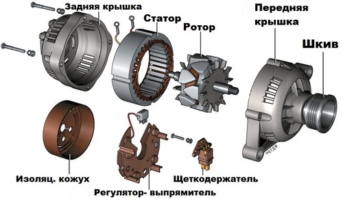
The generator is arranged quite simply. Voltage is applied to the rotor through graphite brushes and slip rings to excite it. It is driven by a pulley through a belt drive. The rotor rotates in bearings. Electric voltage is generated in the stator windings and converted into a constant voltage using six power semiconductor diodes, three of which are connected to the positive terminal of the generator, and the other three to the negative terminal and "vehicle ground".
- If on the dashboard of the car does not go out after starting control lamp, this indicates that the generator does not work and does not give current. But sometimes the cause of the alarm can be poor contact of the connector, wires, or a malfunction of the relay.
- Battery discharge. But keep in mind that sometimes the battery is discharged and does not have time to be charged by a working generator when moving over short distances and with the light and electrical devices of the car turned on as much as possible.
- Generator at engine speed 2000-2500 gives out voltage below the permissible limit of 13.2 Volts.
- If the generator generates a voltage above the permissible limit of 14-14.8 Volts (depending on the model), this indicates a faulty voltage regulator, which leads to a disastrous overcharge for the battery.
Before removing the generator for repair, check:
- Tensioning the drive belt and rotating the pulley, tightening its nut.
- Connection to the car body of the battery and generator.
- The integrity of the fuses.
- Bearing play. It is checked in the same way as for electric motors according to this instruction.
- Before removing and disassembling power unit, if there is generator noise during operation, try disconnecting the wires. If the noise has disappeared, then this indicates a short circuit or interturn short circuit of the stator windings or a short circuit to ground. Repair is not advisable, replacing the generator with a new one will be cheaper. If the noise persists, this indicates bearing wear. They need to be replaced.
- Most often worn brushes are the cause of the malfunction... Check and replace them.
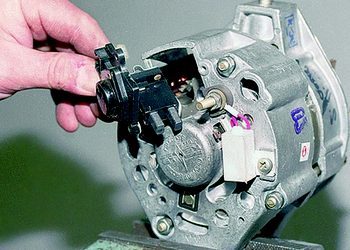
- Poor contact between brushes and slip rings. Check if the spring is not pressing well. It can be stretched or replaced if necessary. Inspect slip rings for scorching or dirt. Use the finest sandpaper for cleaning and a rag for dirt. If the slip ring is severely worn, the rotor must be replaced.
- Damage to the rotor winding can be checked with a multimeter. The windings should ring among themselves for a short circuit or show a small resistance. If the windings are intact, then it is necessary to ring for the lack of electrical connection between them and the case. A defective rotor cannot be repaired and must be replaced.
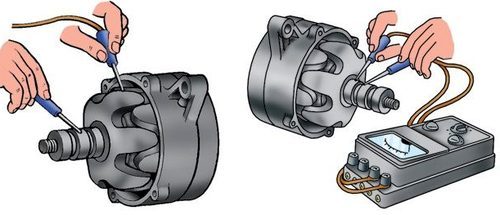
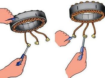
- Damage to the stator winding are checked in the same way. The multimeter should show a short circuit or very small resistance between the terminals. And there should be no electrical contact between the winding and the generator case. The defective stator must be replaced.
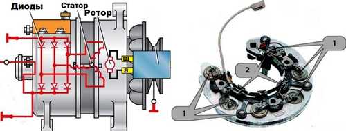
- Check all diodes in the rectifier. They must conduct electric current only in one direction, in the opposite direction (we swap the positive and negative probes) - the resistance is large enough. In the example in the picture, it is necessary to check each diode between points numbered 1 and number 2.
| Video (click to play). |
Recommend additionally will get acquainted with the instructions for repairing synchronous electric motors with their own hands, because they carry out troubleshooting in almost the same way as for generators.

 MTZ
MTZ MMZ
MMZ MAZ
MAZ


