In detail: do-it-yourself transmitter repair from a real master for the site my.housecope.com.
FM modulator or transmitter is cool stuff. Convenient very thing, loaded lard of songs tired of rewriting. You can still listen to music from one modulator together. We have one in the garage span, it is constantly on, so everyone tuned in to it. It looks different, I have such a modulator.
They all have the same functions. Different design of the appearance of the modulator and its memory, some do not have it, and you have to insert an external flash drive.
Okay, more to the point. I was not happy for a long time that the modulator worked flawlessly. When it broke down, there was an opinion like Chinese bullshit. I threw it away on the shelf and somehow managed without it.
Recently I got to the modulator. Disassembled: the breakdown was nonsense. There is a fuse in the modulator plug, which is inserted into the cigarette lighter socket. Burnt!
The same was not at hand.
We take a stranded copper wire. We select two veins from it. I have them with a diameter of about 0.2 mm. Someone will say that this is too much, but the fuse still burned out? And it was 250V 0.25A, which is also quite a lot.
Twist two veins into one cord.
We tie first one contact of the fuse, then the other.
We fix our jumper with electrical tape or paper adhesive tape. It is necessary that the contacts remain bare.
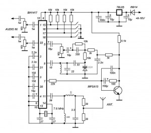
Modulator repair basically boils down to repairing the power supply, which is made in most car FM modulators, according to a simple scheme: a stabilizer on a microcircuit and capacitors. Even the diode shown in the diagram (see below) and capable of protecting against polarity reversal is not present in all modulators.
| Video (click to play). |
Several reasons can lead to the failure and repair of the FM modulator, one I have already indicated is a polarity reversal, then a voltage surge in the car's network (charging relay malfunction, battery disconnection while the car is running) and wire breakage from the power supply to the circuit. I already wrote about these malfunctions in the article "Malfunctions of the FM modulator". When repairing a modulator, these faults are most common. Often there is a failure in the firmware (not in all models and I do not repair such a malfunction, for the simple reason that the repair will be commensurate with the purchase of a new car FM modulator and not all customers go for it).
Let's focus on repairing the fm modulator power supply.
As already mentioned, the power supply is quite simple - it is a stabilizer installed on the board on an IC of the SP7805V2-L / TR type (5 volt stabilizer) and capacitors. When repairing a modulator, start with a visual inspection. We check: whether the capacitors are swollen, for a wire break and whether there is any damage to the stabilizer.

These stabilizers, unlike conventional ones, for example LM7805, have a smaller SMD D-PAK package, and a better ° C / W ratio.
Datasheet 78 M05
It is better to change the stabilizer to a similar one, but if there are difficulties in the radio components, then you can put the usual one by placing it in the FM modulator case and soldering it with wires, preferably providing it with a small radiator.
A week ago I bought a CarMp3Player radio modulator, but just yesterday it started to lag, or rather to hiss, and the song is almost inaudible (no matter what wavelength), the radio is working fine. I understand that China and so on and so forth, but can it turn out somehow to revive it for at least a month? I listen to music on a USB flash drive, songs on a flash drive somewhere around 300MB.
- Take a look at the list of helpful topics in the first post.
- Terms and the most popular patterns in posts are highlighted with quick tips and links to related articles on MagWikipedia and the Catalog.
- It is not necessary to register to study the Forum - almost all profile content, including files, pictures and videos, is open to guests.


... guarantee.
. /. /.
... no. Yes.
. /. /. /.
... throw it out, take a new one. pick it out, don't do it. change and do not take a steam bath
... and take a new one.
took on the market what a guarantee pffff
I hope that something has gone there and this problem can still be solved.


No, I still need sensible advice
Drive to the market, find a seller, change the modulator, take the money.


Throw it away and take a new one (repairs will cost twice as much).,
xs, how these modulators are still alive, now a Chinese 1din radio tape recorder with yusb costs 500r. And on the topic, then of course throw it out and buy a new one, it will be cheaper.
Look at the fuse, it's 99% his fault.
I bought just such probably 10 pieces already in a year, to my friends and myself. Nobody complains, everyone sounds without interference.
I bought just such probably 10 pieces already in a year, to my friends and myself. Nobody complains, everyone sounds without interference.
Ordering is simple - click Add to Cart and pay through PayPal, in which you pre-register and register your visa, with which you can pay online. It is completely safe.
Free shipping. The parcel takes two weeks if the local mail does not mess up. It happened that after three weeks a repeated notification came when I did not see the first one in my eyes =))
In general, the modeler can be powered based on the power supply conditions of the stabilizer - at least from 24 volts, but the stabilizer without a radiator heats up decently.
I decided to make a transmitter out of it for transmitting radio from a satellite receiver to a receiver. By the way, the reception is quite distant - by 20-25 meters, even taking into account the walls.
First of all, I found an old 5-volt power supply unit, from it I used only a board with a rectifier and a case. We change the dried out Soviet electrolytic capacitor to 470 mkf 10 volts, to 25 volt 2200 microfarads, for better filtration. We solder the Chinese transformer, cut off the tap, because we do not need it, as a result, the output turns out to be 13.8 volts under load.
Just in case, I put a 35 ohm resistor so that the stabilizer does not warm up - it is better to let the resistor warm up, since it is in the power supply unit and there is ventilation in it, and the FM stereo modulator case is closed.
In total, at the output of the unit under a load of about 10.8 volts, this is what you need. The stabilizer, in turn, produces all the same 4.9 volts. So everything is in order and the food suits him!
Instead of plugs (we disconnect them at the connector), we solder a piece of wire in rigid insulation about a meter long, now the transmitting properties of the FM modulator reach about 35 meters to an ordinary Chinese receiver! The transmission is naturally in stereo, there is a minimum of noise and the quality, I would say, is excellent.
Finally, some characteristics of the Videovox AXFM modulator:
- Master RF generator with digital frequency synthesizer;
- Selection of the carrier frequency 87.5 - 98.5 MHz from 110 possible values;
- Large LED display to indicate the tuning frequency;
- Memory of the tuning frequency when the power is turned off (very convenient, I set 97.7 and I still have it);
- Stereo coding with pilot tone;
In practice, the stereo works well, the receiver does not hiss even at a considerable distance.
We assemble the case, hang it under the table on double-sided tape next to the receiver and enjoy the radio in any FM receiver). Sometimes my neighbors listen across the road and even motorists in the nearest garages, as it takes 40-50 meters for a good receiver! Comrade was with you. vanesex.
Recently I bought an MP-3 FM modulator: LCD display, 1 gig of memory + a slot for additional memory expansion - a traveling thing! BUT. did not work for a long time, the memory flew off and is not detected through the computer !! Does not keep the frequency settings, volume level and song number. When the ignition is turned off, it starts playing from the first song. Maybe someone has encountered this or a similar problem? These modulators are generally repaired.
My brother-in-law has already changed several of these. They don't work for more than six months. China, however.
Re: Re: Repair MP-3 FM modulator?
doing repairs. such a question how to repair MP-3
I bought it too. It is impossible to listen to music when you go along the trolleybus wires. Therefore, I decided to buy an inexpensive Elenberg tape recorder with a memory card slot and a flash drive for only 3000 rubles.
FM modulator brought to mind! there 3.5jack was this audio input! but due to its (transmitter) simplicity, by the method of scientific poking! - where there is an entrance, there may be an exit!)))) Now I listen to mp3 through the wire, bypassing the radio channel!
rubin4ik Please describe in more detail how to connect the ch.w. modulator. wire conduit
pysy: yes! I also did the modulator for my father! working
pypysy: yes! who has music with mini-disks, make an audio input like 2 fingers obos valt


with a modulator it is clear how to make an audio input I have a radio tape recorder with a TV, CD and mini disks?
according to activity data for the last 5 minutes.
Passed: 41 Age: 41
Passed: 35 Age: 35
Passed: 50 Age: 50
There are 17 birthday people in total.
Most active in the list.
If you need to transmit audio sound over a relatively short distance, then you can assemble the transmitter circuit presented on this page. The circuit is based on two NPN transistors BC547... The range at best will be 70 meters. You can adjust the volume of sound transmission using a variable resistor of 100 kiloohms, as well as on the receiver itself. It is not necessary to install an LED with a 330 Ohm resistor, it serves as an indicator.
I used this device for broadcasting sound so that I could listen to the music I needed while at a short distance from home, for example, in a garage, and receive a signal on an ordinary FM radio. Layout printed circuit board is available - download.
Analogue of imported silicon bipolar n-p-n transistor bc547 is domestic kt3102... The higher the gain of the transistors, the more powerful the audio transmitter will be. If you want to make the device miniature, use transistors in the sot-23 package: BC847... The picture below shows the location of the base, collector and emitter.
The best, in my opinion, the power supply for the circuit will be two batteries AA 1.5 V connected in series. Together they will give a voltage of three volts. The operating time depends on the current consumption, as well as on the capacity of the batteries. Usually, the higher the cost, the better they are. For example, if you use fairly expensive batteries GP Ultra Alkaline, with the manufacturer's declared capacity of 3.1 A at a current in the circuit of 8 mA, this device will be able to work without interruption, roughly speaking 387 hours. The problem is that it is very difficult to “drain” the entire battery charge. Therefore, in reality, the circuit will work without shutdown and with a stable signal transmission for about 150 hours, or almost 7 days.
The coil has six turns of insulated copper wire with a cross section of 0.3-0.5 mm. We wind this coil on the paste from the handle.
When testing the device, the current in the circuit was almost 10 mA.
It is very easy to catch the frequency of the transmitter by twisting the trimmer capacitor and "playing" with the coil, shifting and expanding its turns. I caught my transceiver at 89.90 MHz.
I assembled this circuit on smd parts, only I took the transistors in the TO92 package. An antenna is a piece of copper wire, the more the better. If you just touch the antenna wire, then the frequency does not go away, and if you pick it up, noise starts in the receiver's headphones.
I tried to transmit sound both from the computer and from the phone. Too loud a signal is transmitted with numerous noises and wheezing, the optimum sound strength is adjusted by a trimmer resistor. In general, the audio-sound quality is pretty good. Received on a black and white Nokia phone, and listened to the sound through headphones. There were no big reception problems.
A video of the operation of the sound transmitter is below. Song: bwb - my boys.
On this I say goodbye. I was with you EGOR.
solar batteries novosibirsk do it yourself, solar controller reviews, solar battery review, testing, electric transport, LEDs, motor wheel, do it yourself, solar panels
Redesigning the transmitter for connecting to the CD / MP3 / DVD input of the car radio directly bypassing the FM modulator (Supplemented)
Why do you need to connect directly, you ask, but who has thought about this for a long time?
This is necessary so that there are no intermediaries in the transmission of signals, in this case, in order to bypass it, you need to intercept the signal before it enters the transmitter, and we get a clear sound without interference!
Plus, you get another 3.5 ”cord-in jack for connecting external devices!
To do this, if you have KT0803, and it is installed on all Chinese, cheap equipment. We solder it as drawn according to the wire diagram. And the resulting connector, we connect it to the car radio to the AUX in.
The microcircuit must be dismantled so as not to create unnecessary interference!
And voila, we get high-quality sound, and if we also supply 12 volts from the on-board network connector, we get an independent flash, Sd card, etc. reader!
5- Leg ground
6- Left analog signal input
7 - Input of the right analog signal
The output from the transmitter microcircuit of the kt series is connected to the AUX input of the tape recorder.
Why is this done - we remove the interference of the FM tuner, the sound becomes clearer without radio interference!
chip marking, pin, leg assignment, etc.
Microcircuit connection diagram. Or factory inclusion.
According to the circuit for switching on the microcircuit, you can determine which legs the linear signal is applied to. Next, we solder the microcircuit, and to those two inputs, we solder capacitors with a nominal value of 4.7 / 63 mF / v. And after the capacitors, we output the wires to the nests.
Wed 7 Jan 2014


Many users from different sites, as well as YouTube subscribers, after the video, asked for instructions on how to assemble a bug from the FM modulator. The FM modulator has become quite a popular device recently. It is intended for decoding audio tracks and transmitting over a radio channel. Operating range up to 10 meters.
In order to assemble a bug from a modulator of special skills and knowledge in radio electronics, basic knowledge of a novice radio amateur is enough. We disassemble the FM modulator and discard the case. The filling is powered from 5 Volts, the voltage from the vehicle's on-board network goes to the linear voltage stabilizer, at the output of which we get the indicated 5 Volts, it is this voltage that powers the digital part of the modulator.

Any modulator consists of a small processor (in our case it is not needed, but it cannot be separated from the main board) and a transmitter. The main advantage of such a bug is that the circuit has quartz stabilization, so the transmitted signal is very high-quality and there is no frequency slope observed here.

The circuit can even be powered by a single mobile phone battery with a voltage of 3.7 volts. On the main board, we can see the transmitter IC.

We turn on the radio transmitter and tune the modulator to any frequency; tune the receiver itself to this frequency. Then we take a thin and sharp metal object (necessarily bare), for example a needle, and alternately touch all the pins of the microcircuit with the tip of the needle. When we touch some of the conclusions, we observe distortions in the radio receiver.

We select the output that reacts to touches more than the others, that is, the distortion in the receiver is louder than in the case of the others. Directly to this output we connect (solder) a non-polar capacitor (ceramic or film does not matter) a capacitor with a capacity of 0.1 μF.

We send a sound signal to the free output, when an electret microphone is connected, we will receive a radio transmitter.
I wanted to make the radio headphones with my own hands. Buy, their price is from 700 rubles. I didn’t have this money, and even if I did, I still didn’t buy it. Then there was a bunch of broken fm-transmitters. In this heap was found 1 worker. These modulators have one big problem. They overheat the 5V crank, and therefore they quickly go out of line.
And this modulator is no exception. In the car's cigarette lighter, the onboard power supply voltage is up to 14V. Until this rolls the voltage as at the side net
14B. A after equal 5V. Therefore, it was decided to power our device from the USB connector.
The body was made from an ordinary telephone socket.
We just take nibbles and bite out all that is superfluous from the inside. We try to do everything equally so that the bottom is equal.
We take out the modulator board by unscrewing the small screw from the back side, where it is turned.
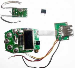
Here's a card. This card is from a broken modulator, on it does not have a USB connector.
We attach to the new body. If it pokes a plaque out of the body, you need to add it. To my regret, I didn’t fit, so I had to neatly grind on files, or nadfiles. It is advisable to grind on a circle, since the plaque is very fragile, especially it is necessary to be careful with the display.
Comparison of the working modulator card, already old (left) and broken not enough (right).
On the back side, I had to break off the slot for the SD flash card. I still don’t use them, so I immediately removed that I didn’t get in the way when grinding.
The entire modulator is quietly placed in the body. Now we need to solder the power supply from the USB connector. We take the usual USB connector (from a mouse, keyboard or from an extension cord) and cut off the PAPA connector (like a flash drive). Solder very neatly, and that does not drip off. Solder the ground (black wire) onto the iron piece on the hook. The photo is shown. Positive contact on the foot of the roll. Mandatory for the one indicated on the photo.
The main part is ready. If someone needs to re-solder the connector, so that it would normally fit into the body, and not burst out of it like this:
Usually in cables from headphones GROUND is either black or gold. A Left channel or Right channel no difference. We solder it directly on the connector itself.
Well, in principle and ready. If you wish to rewire the USB connector more firmly, be careful. Do not confuse anything.
Now we put everything neatly into the body, everything that talks, then we grind. We take the heat and fill in the wire so that they do not fall off during use.
The modulator is controlled via the REMOTE CONTROL. Although the remote control is intended only for the purpose of assuring or switching off the song (when playing from a flash drive). The hole on the case on the other side is specially made for the purpose of attaching the most sensitive receiver. So that you can manage it without difficulty.
Line-in is intended for so that it was possible to connect the transmitter to a computer, laptop, telephone, or player. For example, I use it for a laptop so that you could watch movies, or listen to music on the couch.
ATTENTION. DO NOT USE FLASH DRIVE AND LINE INPUT ONCE. POSSIBLE DAMAGE OF EQUIPMENT.
Well, that's and ready device. You can buy a regular Chinese radio for 30 rubles and listen to it. But I myself use the radio on my phone. But after a while, I will tell you how to embed a Chinese radio into your headphones.
Frequency on the modulator is the very first 87.5. Therefore, the display for this device is not needed at all. This purity is automatically generated when the modulator is turned on.
A few photos afterwards: (in the dark it is beautifully lit).
Made a body. It looks even more efficient. I removed the USB cable (a socket for a flash drive, it turned out to be unnecessary). Made an external antenna to work better.
I found here at my leisure in a box with bins an incomprehensible detail with a jack and a plug for a TV cable or antenna. A sudden question arises: what the hell? Understanding ...
This thing was pulled out of the Funai VIP5000 video recorder before sending it to the trash heap (it was a worker, but already HD 1080 video ... we watch all films online in this quality, but here is a dull VHS).
It turned out that this is an RF (Radio Frequency) modulator that converts the V (Video) and A (Audio) signals output by the VCR (and normally fed through the "tulip" to the TV's video input) into AM-video and FM-audio signals and then mixes them into the TV antenna cable. As a result, in the TV, the antenna cable of which is passed through the VCR, another channel appears (at a certain frequency of the UHF band), which is broadcast by the VCR.
This is what it looks like on the back of the VCR (antenna input and output on the right):
This is necessary in case your TV does not have a video input. Or to broadcast the signal to many TVs in different rooms.
Few people knew that this was possible ... In the late 80s and early 90s, many people did not even think about buying a VCR, due to the fact that Soviet TVs did not have a video input, and they did not know what could be watched through a TV cable.
More specifically, it works like this: plug the TV-antenna cable into the TV-IN of the video recorder, another wire from the TV-OUT into the TV. Turn on the VCR (if it is turned off, the TV set will not show anything at all, because there is an active antenna amplifier between the TV-IN and TV-OUT of the VCR), insert a cassette with the movie "Greek fig tree" and start searching for a channel on the TV in the channel search mode ( somewhere in the UHF band), which is broadcasting this film. If it so happens that the video from the video is mixed with the channel from the air, you need to turn the "RF-channel" wheel on the video recorder (near TV-IN and TV-OUT), this will change the broadcast frequency.Having found the channel from the VCR, memorize it to the "0" button, and now this channel will have "Video" from the VCR. Only the VCR can no longer be turned off for good, otherwise the TV antenna signal will be interrupted.
Now let's start digging how this RF modulator works and how it can be used separately.
Here's what's inside (removed the screen caps on both sides):

The device is divided into two independent (power supply) halves. On the right is a +8 dB antenna amplifier on a 2sc2570 transistor (green arrow), this gain compensates for the losses on the ferrite core, through which the signal is mixed from the left side to the TV-OUT (jack on top). This part is powered by +12 volts (ground - to the case).
On the left side, on the back, there is a 2259 JRC chip, which is powered by + 5V, converts the V-IN and A-IN signals to "air" format and sends it to the mix on the right side. White arrow - change the frequency of the mixed channel, pink arrow - switch the TV system: PAL B / G or PAL D / K.

Here the left part is an antenna active amplifier with a 12 volt power supply, the right part is a converter (RF-modulator on a 2259 JRC chip). N / A is not used.
How can all this happiness be used selfishly for indecent purposes?
Here, a person feeds a video signal from a video door peephole to the input of this device and looks at a picture on a TV on one of the channels (no need to buy a separate monitor in the corridor).
Here people are doing wireless broadcasting from a VCR to remote TVs via UHF antennas.
And here's how you can easily use a separately active antenna amplifier:

We supply only 12 volts to the first contact on the left (ground to the case). You also need to close the contacts indicated by the orange and cyan arrows (to turn off the ferrite adder [circled in green] so that it does not attenuate the signal). Truncated, the signal is wildly (8 dB) amplified ...
Purely to heighten knowledge:
- The pink arrow points to the signal mix point to the right, from 2259 JRC.
- The green oval encloses a ferrite adder-transformer (it has significant signal level losses, probably about 8 dB, for which an amplifier was added).
- Directly from the cyan arrow upwards - TV-OUT.
- A red oval is a 2sc2570 transistor (npn, high-frequency up to 5 GHz, low-noise 1.5-3.0 dB, gain 8 dB), its base is at the very bottom (TV-IN is fed to this base through a capacitor from below), an emitter is in the center, a collector is at the top ( to which 12 volts are supplied through a resistor, so that at the collector-emitter junction there are 10 volts, as needed by the datasheet for this transistor), then the signal goes up from the collector through the adder to TV-OUT.
Here is a circuit of an antenna amplifier based on 2sc2570 (but usually they do not use this transistor, since there are transistors that are much better for such amplifiers, for example, T67, V3, 415, BFG67, BFR91A):
Hello everyone, they brought me a VCR for spare parts. The power supply unit died. Looking through the VCR board I saw an interesting module with a connector plugged into it (from the amplifier it seems):
After 5 minutes of searching on the Internet, I found out that this is an RF modulator for transmitting high-frequency signals to old TVs.
Since the BW is idle, the Vityaz tube TV and the samsung dvd player, it was decided to use a modulator in order to watch movies in the kitchen from a USB flash drive using a dvd. Used materials at hand.
all negative wires to the modulator body. power supply - 4.5v 1A:
Modulator body - from shoe sponge. Antenna plug - the one that was plugged into the modulator. Ready modulator:
It will be about how to make the simplest and cheapest radio transmitter that anyone who does not even understand anything about electronics can assemble.
The reception of such a radio transmitter occurs on a regular radio receiver (on a landline or in a mobile phone), at a frequency of 90-100 MHz. In our case, it will work as a radio headphone extension cable from the TV. The radio transmitter is connected to the TV via the headphone jack via an audio plug.
It can be used for different purposes, for example:
1) wireless headphone extension cable
2) Radio nanny
3) A bug for eavesdropping and so on.
To make it we need:
1) Soldering iron
2) Wires
3) 3.5mm audio plug
4) Batteries
5) Copper varnished wire
6) Glue (Moment or epoxy) but it may not be needed
7) Old boards from radio or TV (if any)
8) A piece of plain textolite or thick cardboard
Here is its circuit, it is powered by 3-9 volts
The coil should be wound according to these parameters (7-8 turns with a wire with a diameter of 0.6-1 mm, on a 5mm mandrel, I wound on a 5mm drill)
Be sure to clean the ends of the coil from varnish.
Hello dear friends!
I want to tell you about a compact FM transmitter for connecting to audio devices via a 3.5 mm audio jack. The transmitter allows you to broadcast an audio signal over radio frequencies in the range from 87.5 to 108.0 Mhz. I ordered it for a friend, taking into account the price and attractive design (he asked for an inexpensive one to listen to audiobooks in the car). Before giving it to him, I disassembled it a little and tested it. The review contains detailed photos and impressions of the operation.
Delivery within 19 days, packed in a bubble wrap, contents intact.
V set the device itself and a micro USB cable for charging the battery, cable length 30 cm. The design of the transmitter is simple and concise, stylized as Apple products.


During charging, the state of charge is displayed (4 levels):

The transmitter can be connected to any 3.5mm headphone output: phone, laptop, mp3 player, computer, etc.

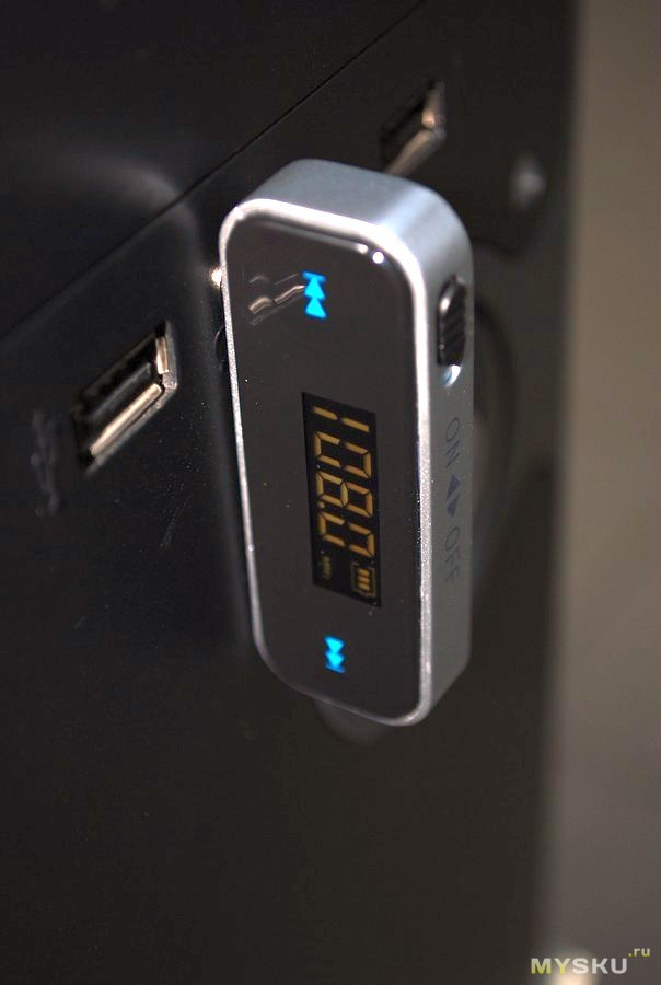

Connection and configuration are elementary:
1) Turn on the device with the onoff slider
2) Set the desired transmission frequency, for example 87.5 Mhz
3) Apply audio signal from source
4) Tune in the receiver (another phone, radio in the car, etc.) to the frequency 87.5 Mhz
5) Experimentally adjust the sound level at the receiver and source (to minimize radio interference)
Snap-on case, easily disassembled with a plastic card:
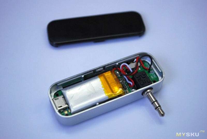
Microcircuit without designations, just in the form of a drop. The battery is also unnamed.

The backlight is bright enough, the numbers are easily distinguishable. After a few seconds, it goes out by itself.

The battery lasts for 5-6 hours of continuous operation. Estimated battery capacity 180 mAh.
The audio signal transmission quality is average for this class of devices. In a quiet room at a distance of 10 m from the source, weak radio interference can be discerned in the headphones. For testing, it transmitted an audio signal from the phone to the phone (the antenna in this case was the phone's headset).
In principle, this interference is barely perceptible, I removed them by adjusting the volume of the audio signal on the transmitter and receiver. In a car, this interference is not noticeable.
Purchase:
After buying and receiving the device, I found out that there are transmitters with a similar design, but with more solid characteristics.
For example, here is such a more expensive and better performance model BFM26
As far as I can tell, at the moment, this is the best option that can be ordered on the Internet, based on a specific design.
Conclusion: The universal FM transmitter has been tested and found to be serviceable, all functions are normal. During testing, I did not find any anomalous behavior.
Pros:
1. Nice laconic design
2. Versatility and ease of use
3. Autonomy (5-6 h)
4. Compact size
5. Decent quality of audio signal transmission
6. Display backlight
7. Transmitter can work while charging
Minuses:
1. There is no instruction
2. Microcircuit on the board without designations
3. No data on battery capacity
Thank you for your attention, all successful online shopping!
P.S.
About stereo:
The number of wires that go into the plastic seal of the audio plug and the designation on the board indirectly hints to us that there is stereo.Since the main microcircuit is not signed and it is impossible to look at the specification for it, it is difficult to say something definite about it.
It would be interesting if the owners of such devices, of which there are many judging by the comments, posted a photo of the disassembly and could be compared more objectively

I will add a useful comment from a Muskovo resident with the nickname lockeron:
“A good transmitter, I took one myself. You can take a look at my video reviewer on it:
Date: 09/08/2015 // 0 Comments
It is useful for novice radio amateurs to know how to assemble FM DIY transmitter. There are many different schemes walking on the Internet, but some of them are too complicated and require certain installation and adjustment skills, while others turn out to be completely inoperative and useless.
The diagram is very simple and can actually be assembled from scrap materials, the ratings of the components used are indicated in the diagram. Assembly and selection of parts took no more than half an hour. The ratings of small capacitors C4, C5, C6 were taken from the old SKM24 unit, everything else can be found from old boards of any radio equipment.
For clarity and test the operation of the device, the circuit was carried out by surface mounting on one of the old boards of a Soviet TV. Conditions were not set for the quality of the installation, the main goal was to check the circuit itself.
There was no receiver at hand and used a regular radio from a Nokia. A properly assembled circuit starts working immediately, and the test sample wound up at 102.9 MHz. The transmission range in the room does not exceed 25-30m (three to four brick walls). The input was a signal from the audio output of the computer, power was supplied from the USB port (because of this, a small noise in the form of a weak hum is partially heard, there is no such effect from the battery). The antenna was not connected to the output at all.
It took some time to catch the transmitter wave, because the transmitter signal was superimposed on one of the local radio stations. If you stretch or squeeze the turns of the L1 coil slightly, the transmitter frequency will change slightly, after tuning to the required frequency, it is better to fill the coil with paraffin or wax.
All that remains is to assemble the device into a case. Applications for such an FM transmitter can be found in the most unusual, ranging from an ordinary car transmitter to a simple homemade baby monitor.
1. Take the FM transmitter and remove the front panel from it. Usually such devices are assembled on disposable latches, but in my case there was also a screw. So don't overdo it. It would be ideal to pick it up with a knife and a small slotted screwdriver and snap off one mount and then use the same screwdriver to push back all the others (whoever disassembled the phone or laptop at least once will not experience difficulties).
2. Next, remove the board (I have it tightly sewn to the player board with a loop - in this case, just bend it back) and look for the designation "DC5V" - this is just a 5-volt power supply. If it is not there, then we do this: we cling to the cigarette lighter socket the usual 12 volts and see where they turn into 5. We remember the place and, after turning off the 12-volt power supply, we cling to the previously memorized + 5V place (minus you can use the standard one). For those who haven’t worked with cigarette lighters, I’ll tell you: + 12V is a small contact in the center, and 2 mustaches on the sides are a minus (hereinafter, due to my habit and illiteracy, I will call minus “mass”).
3. After we have found a place where you can power the device with five volts, we will make a power cable. A regular USB cable of 1.0 standard (compatible with 2.0 - there are most of these) contains (in addition to the braid) 4 cables. Green and white can be cut off at once - this is purely for data. We need black and red. Red is a plus, black is mass. Cut off the excess and strip the remaining cables. It is better to tin them right away (for those who solder for the first time, it will be useful to read the reference books first).
4. Now we will cut a hole for this cable in the transmitter housing. I did this: First, I heated the needle with a soldering iron and pierced the case.Then, using a screwdriver and various drills, gradually (so that the body does not crack), he increased the diameter to the desired one. Attention! Make sure that the hole does not cover anything (latch or microcircuit)
5. Now push the cable through the hole and fix it with super glue and fix it from the inside. Take 2 wires from the third point (you released them with a margin, right?) And solder them with a thin sting (do not hook the microcontroller!) To the contacts from point 2.
6. Without closing the case, we run to the nearest computer for the test. If the modulator turned on, and black smoke did not come from the computer, then you did everything perfectly and you can close the case. In my case, the latches turned out to be very flimsy and I had to save myself with the same superglue.
7. And I was already happy and listened to my favorite music on my favorite receiver, but after walking a couple of meters away I saw that the sound had disappeared altogether. Not enough range. As a temporary solution, you can attach a piece of wire as an antenna, but it is better to walk to the radio store (and if you read the section "we need", then you have already walked) and buy a not very large antenna. A small antenna is needed immediately for 2 reasons: firstly, the modulator is not particularly heavy and a long antenna directed upward will outweigh it, and secondly, a long antenna is a long range, and we absolutely do not need the whole city to hear the station (you hopefully remember that you need a license to broadcast on the VHF band). 30-45 cm will be the best option.
8. "Where to insert it?" Is the question you are likely to be asking. There are several options, but I got by with the simplest. I inserted the antenna where the center connector for the cigarette lighter used to be. If this suits you, we do the following: unscrew the connector cover and shake out the "pimp" from there (can anyone come up with a more adequate name?) And the fuse. We wrap the antenna with electrical tape in the place where it will be inserted into the vacant "niche" (or we bore the niche itself to the required parameters) so that it slightly presses on the spring (there was no need to pull out the spring! Put it back!) And tighten the lid.
9. As a result, we get approximately such a device, with a range of about 300 meters. This is quite enough for "hanging the radio around the house or around the house of neighbors." He eats such a "baby", taking into account the modifications, about 120 mAh and discharges my laptop battery in 6 incomplete hours (along with the writing of this article). The only inconvenience was the need to pull 2 wires (the wire from the headphone jack to the modulator jack and power from USB).
10. A few tips for using:
Why do you need what you have done / are about to do:
The author disclaims responsibility for your crooked hands and, in general, any harm caused during the manufacture / use / storage of this device.
| Video (click to play). |
The author also thanks Segras for an invaluable contribution to the process of preparing an idea and its implementation! Thanks!

