In detail: do-it-yourself repair of the cadena digital set-top box from a real master for the site my.housecope.com.
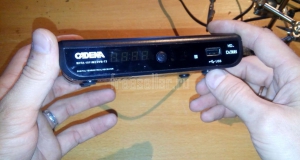
I have two TVs in my house and both of them work through Cadena dvb-t2 consoles and it turned out that at about the same time both of them stopped working. Repair of such a set-top box costs about 600 to 800 rubles, a new one costs from 1200, it turns out it is too expensive. It was decided to try to fix it on our own, for this “googling” the vastness of the Internet, a solution was found, which I want to show you. As it turned out, this is one of the main breakdowns.
The main symptoms of a breakdown of the console:
- when the set-top box is connected to the network, the red indicator lights up and the set-top box does not react to anything else.

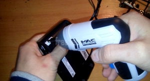
First of all, we disassemble the attachment and carefully examine its insides, special attention should be paid to capacitors. As shown in the photo (circled in red), the capacitor is swollen, unlike the capacitor (circled in blue), therefore it is no longer working and must be replaced.

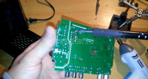
Then we solder the capacitor, look at the parameters and look for a suitable one. In this case, you need 10 volts and 1000 microfarads, as well as 105 degrees Celsius. But in my case, only 10v1000mph and 95Hz were available, and it is slightly smaller in size, but as practice has shown, it works great.

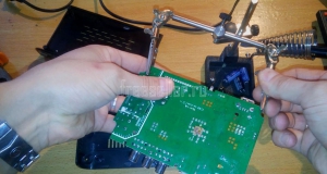
Now we solder the new condo in place of the old one and, as you can see in the photo, everything is fine. (marked in blue).

We check the prefix for operability and put the case back.

I also recommend watching a video clip in which there are moments that were not included in the photo report.
Information
To leave your comment - register or enter the site under your name.
| Video (click to play). |
The most common malfunction of digital television set-top boxes is the failure of the power supply. In such an unpleasant case, it is very good if the model of the set-top box was with an external adapter, bought a new one and look further! And if not! And the power supply was built into the box itself? Then you have to repair or purchase a new one. But maybe there is an easy way out!
Hello dear readers! In this article, I want to share one simple repair method that anyone who knows how to hold a screwdriver and a soldering iron can do! Moreover, it is not necessary to master these tools masterfully.
I'm also not going to tell you anything overly complicated in the field of electronics repair, this is the lot of professionals. On the contrary, I will try to describe everything in such a way that even a non-specialist could cope and eliminate this malfunction.
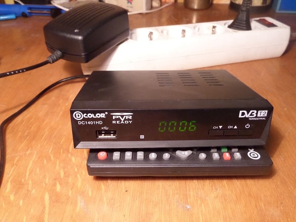
I'll make a reservation right away that this method is not suitable for all models of consoles, but for many, since they are often made according to a scheme very similar for this case. Everything will be based on a specific example of a set-top box from the D-Color company, namely the DC1401HD model. So by understanding this "high technology" you can repair your digital TV box yourself.
Fast navigation through the article
What is a sign that it is the power supply unit that has failed in the console, and not something else? If the set-top box connected to the outlet does not show any signs of life, neither the digital indicator nor the LED on the front panel is lit, then with a probability of 99% the reason is in it, in the power supply.
If, at the same time, the warranty period has already expired, then you can safely do the disassembly. As the experienced masters say, "An autopsy will show" I think you will deal with this part of the work without a detailed description, just be careful, usually two screws on the back wall, sometimes also on the sides allow you to release and open the top cover. Plastic latches on the sides and bottom hold the front panel, and the board itself is also fixed with screws to the bottom of the case and in the area of the connectors on the back of the case.
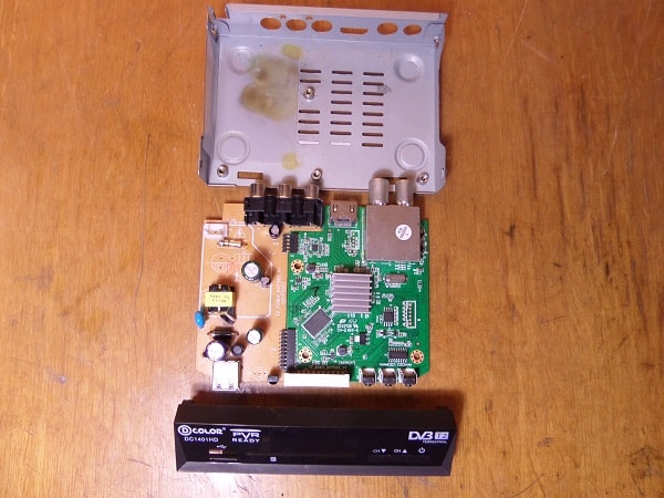
So, the set-top box is disassembled, the power cord is also removed from the connector, it is no longer needed. On the bottom of the case you can see traces of a "fire" that left behind a burnt-out power supply unit.
P.S. The power supply unit here is not a separate unit, as you might think from the name, but the section of the board on which the radio elements are located, providing the required power supply voltage for the set-top box.
I will outline the general picture, and for those who already know a little about radio engineering, this will already be enough to grasp the basis of the idea and repeat. So, the power supply circuits of this set-top box give out only one voltage - 5 Volts. Since this circuit has burned out and repair may be impractical (in terms of the aggregate cost of radio components and repairs), that is, a simple solution. Replace the internal power supply with an external one. It's not very difficult!
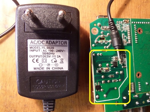
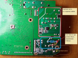
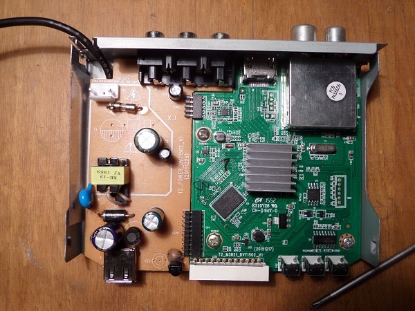
In the photo above, with a yellow frame, a section of the power supply unit that has failed is highlighted. The board has already been washed, so no traces of burning are visible. By the way - Among the repairmen, the expression "Burnt out" does not always mean literal burning with charring and other similar manifestations, it only means that the radio components are out of order.
For our repair, you will need to purchase an external power supply with an output voltage of 5 Volts and capable of delivering a current of 1.5 or better 2 Amperes. Now there are a lot of similar ones and can be purchased not expensively, or maybe you have a similar one, for example, an unused charger from a tablet or smartphone.
When a suitable adapter is available, it remains to find the desired point on the board of the set-top box and, observing the polarity, apply voltage to it from the external power supply. Everything! It remains to lay and secure the wire, or you can organize a detachable connection, as you like. I think the basics are clear, let's get down to the details.
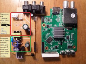
Just a little bit of basics for those who are not in the subject, so that you can figure it out. Pay attention to the photo. Click to enlarge.
In short, the power supply consists of:
- The primary "Hot" part - Hot, it is called because it is dangerous, connected to the mains voltage of 220 volts. Please note that even after unplugging from the outlet, for some time, there is a charge that can bring brr .. unpleasant sensations if you climb there. But in our case there is no need to climb there and we will not connect it to the outlet either.
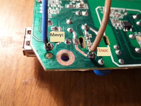
- Secondary part - Safe there, there is a galvanic isolation from the mains. In the given example, at the points indicated in the photo, a voltage of only 5 Volts comes out from the rectifier diode.
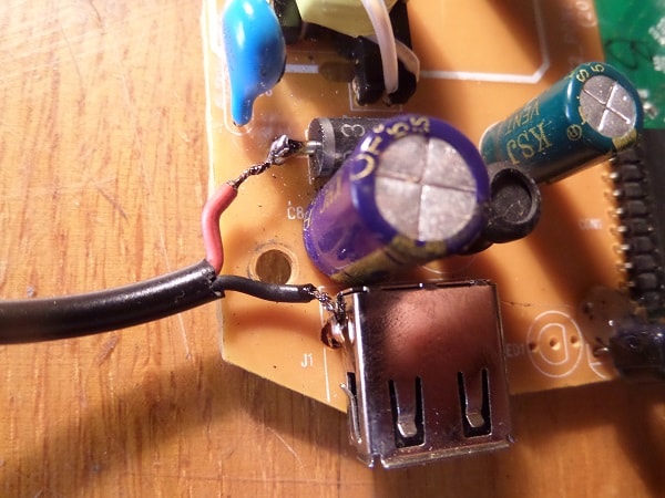
In the purchased, external power supply (at least 1.5 amperes, 5 Volts.) We bite off the plug, clean the ends of the wires and, having determined the polarity, we solder them: Positive to the diode terminal, on the side where the strip is drawn on it, and the negative to the common bus - the body of the USB port will be a convenient place for this. If you do not know how to determine the polarity, even without a device, see additional materials at the end of the article.
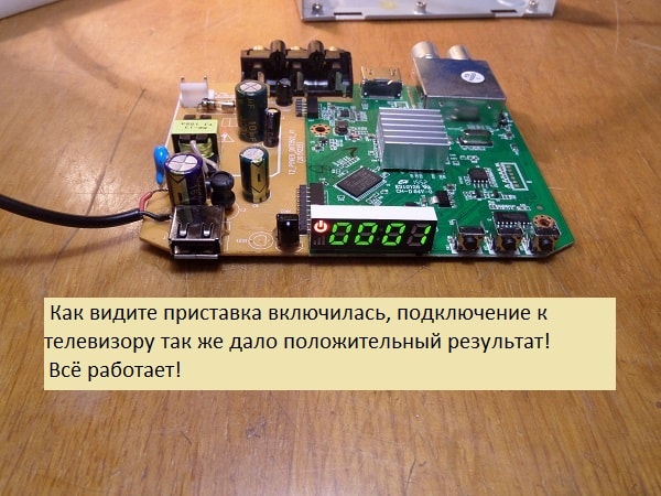
We connect the new power supply to the network, take it out of standby mode, check what happened.
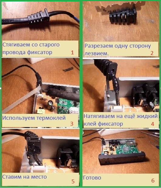
All OK! It remains to lay and secure the wire so as not to accidentally pull it out, collect everything in a heap and use it. In the end, it will look like this.
If you need ideas on how to attach the wire to the box? How to determine polarity without a device? Or how to solder the wire from the bottom of the board? - Then these additional materials are further in the text.
For those who have a multimeter, it will not be difficult to determine the polarity of the power supply, but what about those who do not have this device?
There are several simple ways:
- You can determine the polarity by the color of the wires. There is a rule - the Red wire is a plus, respectively, the other wire is a minus. This is almost always the case! Nearly! Sometimes there are exceptions, either the wires do not understand what color, or the rule has been violated.
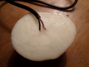
- There is another way, it will be needed - just don't laugh ... potatoes.Yes, yes, raw potatoes! The method is as follows. Cut the potato in half and stick the bare copper wires from the external power supply into it, at a distance of about 5 mm from each other. We plug the PSU into an outlet and wait. With the adapter voltage of 5 volts, it took about three minutes for a visible result. Click on the photo to enlarge.
The potato around the positive wire begins to turn green, so you can accurately determine the polarity without instruments.
In the first, simplest version, the wires were soldered from above, directly to the terminals of the radio components, but you can do it a little differently, run them from the bottom.
In this case, the wire to the case will pass under the board, from the bottom.
On this occasion, hastily prepared a small photo report with a short, step-by-step description of the actions. Hopefully this will be enough.
By the way! Such alteration can be arranged in order to adapt the digital set-top box for use in a car. You just need to use a 5 volt 2 ampere car adapter.
That's all! Success to everyone! I would be glad if this information helps you with something!
And now, so to speak, the repair manual
Capacitors:
1 - Problems with the image on the AV output (no image, noise in the picture), sound claps.
8 - Does not start - hangs on the boot; the splash screen appears, and then the blue screen again. In this case, the capacitance, when measured, can correspond to the nominal (low ESR of the capacitor).
9 - Does not turn on - there is no image at all
13 - seems to slow down too
14 - the picture slows down, the image is strewn.
15 is the same as 14, but 14 is more important.
"Does not catch channels" - quartz between C13 - C15
Capacitors in the power supply:
These two capacities affect the performance of the power supply. The power supply unit either does not work at all (output voltage is 0V) or gives a low voltage of 1.7V.
Container 2 swells - you can see it or the insides come out from below.
2. Output AMS1117 - 1.8 V, if there is no such value - go to point 3
3. It should be 3.3v, if there is no such, then the problem is in the capacitor nearby or in the AS11D itself
4. There should be 1.34 V, but even if there is so much, then the problem is still, most likely, in the capacitor - it is better to change it. In this case, nodes 2 and 3 show normal stress values. This is the case when the receiver starts to load and cannot completely do it - the problem is in the capacitor of node 4. AS11D in this node is also not excluded, but the probability of its malfunction is very small, compared to the probability of poor capacity.
THE LARGEST NUMBER OF FAILURES RELATED TO CAPACITIES 8 AND 9 (SEE 1 PHOTO) IF EVEN THE PROBLEM IS NOT IN THEM, WE CHANGE THEM AS A PREVENTION.
Warnings: 1
Posts: 395
Warnings: 1
Posts: 395
Warnings: 1
Posts: 395
Warnings: 1
Posts: 395
Warnings: 1
Posts: 395
On the 1st pin of the IC 2.9v., 2-0v. (Case), 3-1.27v., 4-5v. (In.), 6- 0.6v., These are voltages for 3.3v. IC. On the second IC just lower the voltage on the 6th leg - 0.13v. Raised the choke, the voltage increased to 4.7v. at the exit. IC. Is it a stub in defense?
Resistor divider resistors 56kOhm
its load is only 180mA
I tried to close the divider resistors with tweezers, it reacts to the resistor from the output, by pedaling the voltage to 0.6v. at the output, which does not react to the short circuit on the case.
They brought the receiver for repair. We switched on the 12V power supply instead of 5V.
Failed DC / Dc converters SY8088 (Output short). These CHIPs were not at hand, I installed external adjustable conversion modules, everything worked.
While repairing, I sketched where and at what voltages the stabilizers and where on the board they are located. T.K. I did not find the chassis diagram, maybe someone will come in handy for repairs.
P.S. 1.2V power supply to the core, 20 ohms ringing for ringing. This is normal, the core consumption is 230mA
Cadena SHTA 1511 S2, over-the-air overview.
More recently, we showed you our review of this receiver, in which we watched how it works. Today we will analyze the Cadena SHTA 1511 S2 digital terrestrial receiver, we need it in order to understand what components are used in this receiver.
Looking closely at the plastic housing of the receiver, we see that it is secured with four screws. The screws are simple, without any secrets, we unscrew them without unnecessary efforts and problems.
Cadena SHTA 1511 S2 receiver housing.
Cadena SHTA 1511 S2, receiver decorative cover
The cover was removed from our terrestrial receiver, now we can look at what this receiver has inside.
Cadena SHTA 1511 S2 receiver main board, general view.
Let's start our inspection by looking at what the receiver has as a decoding device and we can see a quite decent and high-quality item that the manufacturer has chosen.
Cadena SHTA 1511S2 receiver decoding module.
Now let's see what our main board consists of, as we can see everything is combined on it, the power supply and the main motherboard are made in the same case.
Cadena SHTA 1511S2, digital receiver power supply.
Now let's turn our attention to the marking, how we can see the information. Here is a detailed marking from the manufacturer, applied with paint, as we see, the Russian presence is not noticed here.
Cadena SHTA 1511S2, main board information.
Another feature is the fact that in this receiver the front panel is integrated with the common board.
Cadena SHTA 1511S2, receiver front panel.
This moment undoubtedly reduces the cost of the final product and reduces the number of components used. This increases the endurance of the device to external influences.
Cadena SHTA 1511S2, digital receiver memory.
Now let's look at the memory of the device, there is a classic octopus, which after a certain time of operation can be reset to zero.
Cadena SHTA 1511S2, power supply module.
Now let's take a look at the power supply, we will not talk in detail, the photo clearly shows what is used in this receiver.
Cadena SHTA 1511S2, front panel control IC.
Cadena SHTA 1511S2, digital terrestrial receiver memory.
We smoothly reached the central processor, in order to look at it, we need to remove the radiator.
Cadena SHTA 1511S2, digital terrestrial receiver central processing unit.
The heatsink was removed and the numbers of the central processor are revealed in front of us, as we see a rather unusual solution, not many manufacturers use it as the main stone.
Cadena SHTA 1511S2, CPU heatsink.
And here is what a radiator looks like, which is designed to remove heat from the central processor, of course, something more could be glued.
Cadena SHTA 1511S2, receiver video output control module.
Cadena SHTA 1511S2, receiver main board, general view without heatsink.
Cadena SHTA 1511S2, digital receiver tuner.
Now let's take a closer look at the main display of the digital terrestrial receiver, there is nothing to add, everything is clearly visible.
Cadena SHTA 1511S2, front panel, receiver display.
Cadena SHTA 1511S2, control button, LED.
At the same time, you can look at the connector for connecting external memory to this device, in principle, it will be quite difficult to break it.
Cadena SHTA 1511S2, external drive connector.
Cadena SHTA 1511S2, screw securing main board to plastic tray
It is also worth taking a close look at how the connectors to which the antenna is connected are dropped. Everything is visually normal, but you should not abuse the strength, it can be easily broken if used with excessive force.
Cadena SHTA 1511 S2, antenna connectors.
And finally, I wanted to take another look at how the power cord is connected to this receiver.
Cadena SHTA 1511S2, mains cable connector.
Cadena SHTA 1511S2, digital receiver power supply transformer.
Cadena SHTA 1511 S2, capacities on the main board.
Cadena SHTA 1511 S2, external power supply protection module.
Well, you can end there. As you can see, the prefix is quite tolerable and made with high quality. Components are used by leading manufacturers, we see that there is a stock. It all depends on what software will be on it.
Why can't a person find the videos they want on Youtube? The thing is that a person cannot come up with something new and look for it. He was out of fantasy. He has already watched a lot of various channels, and he no longer wants to watch anything (from what he watched earlier), but what to do in this situation?
In order to find a Youtube video that suits your needs, it is imperative to keep searching. The harder your search is, the better your search result will be.
Remember that you only need to find a few channels (interesting), and you can watch them for a whole week or even a month. Therefore, in the absence of imagination and unwillingness to search, you can ask your friends and acquaintances what they are looking at on Youtube. Perhaps they will suggest original vloggers that they like. You, too, may like them, and you will become their subscriber!
Online mp3 cutting is convenient
and a simple service to help you
create a musical ringtone yourself.
YouTube video converter Our online video
the converter allows you to download videos from
YouTube website in webm, mp4, 3gpp, flv, mp3 formats.
These are radio stations to choose from by country, style
and quality. Radio stations all over the world
over 1000 popular radio stations.
Live broadcast from webcams is made
absolutely free in real
time - broadcast online.
Our Online Television is more than 300 popular
TV channels to choose from, by country
and genres. Broadcasting of TV channels is free.
A great opportunity to start a new relationship
with a continuation in real life. Random video
chat (chat roulette), the audience is people from all over the world.
What to do if the DVB-T2 receiver does not turn on, or, as it is called in another way, a digital TV set-top box? From personal experience, I can say that if some device does not turn on at all, the repair will be much easier than when the device works intermittently. We look.
Second channel -
VK group -
BroadBatdTV Affiliate Network -
Instagram - Malfunctions and possible repair of DVB - T2 set-top boxes. TV repair after lightning. LG RZ 15LA70. The T2 oriel 304 prefix does not turn on. Unable to buy a tool - I will do it myself (soft hammer). Repair of TV set-top boxes OpenMax HD DT210 DVB T2. REPAIR DIGITAL TV BOX DVB T2 DOES NOT INCLUDE. repair of digital TV set-top boxes. How to install, connect and configure a digital terrestrial receiver TV DVB T2. We are repairing the T2 World Vision receiver, it does not turn on. DVB-T2. Separate power supply. Repair and reasons. Digital TV set-top box. Renovation, revitalization. How to connect a DVB-T / T2 set-top box to a TV. Watching digital TV! quick repair of the set-top box the signal hd 200 does not turn on (the LED is blinking). The digital TV box does not turn on. And what's inside 🙂 DVB-T2 We open the case and see what we see there.
1. My console is out of order. Stopped working. Where to go for repairs?
For warranty service, we recommend that you contact the trade organization (seller) where you purchased the set-top box. Confirmation of your right to warranty service is a document (sales receipt) confirming the purchase of your set-top box.
If for some reason you are unable to apply for warranty service for the set-top box to the seller, we ask you to inform us about this by sending a request from our website with a detailed description of the problem you have identified in the box. Link to fill out the request form: Ask a Question
2. Can you please tell me where to get the firmware for the Cadena console?
You can find up-to-date information about the firmware, as well as the file for downloading, in the "Useful software" section, following the link: Useful software.Please note that the installation of software versions not recommended by the manufacturer and not presented on the website can lead to the failure of your receiver, as well as be the basis for refusal of warranty service.
3. I purchased a Cadena ST-203AF DVB-T2 digital receiver, for some reason the sound is not always reproduced when watching movies from USB. What needs to be done in order for the video to play with sound?
Most likely, the video file was recorded with audio encoding in AC-3 format, i.e. with support for technology of multichannel digital sound Dolby Digital Sound. In most models of entry-level Cadena digital receivers, the manufacturer does not provide support for this technology. At the moment, the receiver, which has implemented support for Dolby Digital Sound technology, is:
- CADENA CDT-1632SBD, you can find out more about the model by clicking on the link: CADENA CDT-1632SBD
4. My Cadena receiver stopped showing some channels! Can you please tell me what needs to be done?
The broadcasting of television channels in the DVB-T2 standard on the territory of Russia is carried out by the Federal State Unitary Enterprise Russian Television and Radio Broadcasting Network. This organization periodically carries out preventive work to change the broadcasting parameters of channels on the territory of the Russian Federation in order to improve the quality of broadcasting, which can lead to short-term disconnections of some or all channels. Thus, if you find out on your Cadena set-top box that some of the channels have disappeared, we recommend that you contact the regional representative office of the Federal State Unitary Enterprise “Russian Television and Radio Broadcasting Network” to receive information about the preventive maintenance and changes in the broadcasting parameters of channels in your region.
If maintenance work is not carried out, and the set-top box still does not show all channels, you need to contact the sales organization where the set-top box was purchased to obtain warranty service. The proof of eligibility for warranty service is a document confirming the purchase of a TV set-top box.
5. The set-top box has an RF output: IEC male 75ОМ. What is it for? Is it possible to connect a set-top box through it to a TV that does not have any inputs other than an antenna?
Some models of CADENA receivers have an Ant.output (RF-out) connector that allows you to transmit the Ant. input (RF in) a signal from a television antenna without any processing to other devices - loop output (LOOP). This high-frequency TV signal (signal from the antenna) can be transmitted with a cable to the antenna input of another set-top box or to the antenna input of the TV to search and tune TV channels received by the antenna.
6. Is it possible to connect the set-top box to a TV that does not have any inputs (or are faulty) except for the antenna and watch digital TV channels?
Can. To do this, you need a DVB-T2 digital terrestrial receiver with a built-in HF modulator, which can be tuned to one of the frequency television channels in the UHF range (channel 21-69). You can connect a TV to such a receiver using an antenna cable, tune it to 21-69 channels and watch digital TV channels, while the control and switching of TV channels will be carried out from a digital terrestrial receiver. To date, this feature has been implemented in the following Cadena receivers:
CADENA HT-1658
MAIN: KLF7816_T2_02 A4
percent: ******
flush: 25Q32
shim BP: VIPER22
Read from the working device.
You do not have access to view the attachments:
1. Please log in or register.
2. You must have 15 (FIFTEEN) or more messages.
3. You can buy access to files from us.
_________________
It all depends in this house onom
From you from yourself:
If you want, you can become Budyonny,
If you want - horse it!
(V.S.Vysotsky)


Number of views on Youtube 43745
Link to video page:
HTML link to video page:
Latest comments on the site
10 STRANGE THINGS THAT HAPPEN TO US IN DREAMS - Watch / download
⇒ “I had in a dream all of the above, except sleepwalking, this, thank God, was not even in childhood!)“
Added - 10/17/2018 Neuromonakh Theophan - who he really is / vDud - Watch / download
⇒ “What is the name - "Neuromonakh" :)) Who has already watched it?“
Added - 10/17/2018 Italians are trying Russian preparations for the winter. - Watch / download
⇒ “A very positive video. I immediately wanted something spicy. The Italians were obviously laughing in front of the camera. They really liked it. They have a lot of spicy food. But this, you see, has not yet been tried. “
Added - 10/17/2018 Not a scoop - Watch / download
⇒ “Shariy is truly a professional journalist. Every day he makes high-quality video investigations of current events. I enjoy watching his channel.“
Added - 10/17/2018 Machine World 2 - FIRST RUSSIAN REVIEW! - Watch / download
⇒ “when will the game be released and how did you download it“
Added - 10/17/2018
How to replace the MT3410 buck converter (marking on the AS15D housing)? Stands at the power input in the CADENA HT-1110 digital TV receiver-receiver (5 volt power supply). Are there any analogues in Chip and Deep?


Buy a dozen on aliexpress
depending on what currents, otherwise it may 7805 or 1117
Sergey, where are the analogs !? The 7805 is a simple linear regulator with up to 1 amp output. The MT3410 is a high efficiency buck converter with up to 1.3 Ampere output current.
Michael, an analogue of as15d not? By characteristics !?
Sergey, the transformer is in this place because:
1. It works in pulse mode.
2. In this mode, the efficiency is higher.
3. Economical.
4. No unnecessary heating.
5. Output current up to 1.3 A.
7805 cannot be put here because:
1. Works in linear mode.
2. In this mode, excess consumption even in the off state of the main device.
3. Eats like a mammoth.
4. Heats up, and it is not sickly.
5. The output current is up to 1 A, which means that it will heat up even more than it should.
6. Result - it will burn almost immediately.
Michael, why should I tell all this? I do not mind, put at least a separate power supply, what have I got to do with it?
Sergey, to the fact that you told me that these are analogs
Mikhail, I did not say that THESE are analogs, I said there are analogs in general
Sergey, AS15DD is sort of like marking the MT3410 chip =) I ordered this one. Then I just saw that there is AS11D on the photo. Datashit could not find something. I'll check in practice whether it works or not)
Digital TV set-top box repair. Reflect Digital (Oriel, REXANT, CADENA).
hello everyone in this video we will repair the reflect bt-2 digital television set-top box what is vilnius faulty now i
I plug in there is no indication when you press the power button, 3 rotten strips barely noticeably appear
such can be seen like this, before you start you need to disassemble it, I unscrewed the cover beforehand and what we see inside is the light as
you can see the capacitor flowed out from below and flooded the diode bridge that goes along the power input will receive like this in this
case, I have now replaced the capacitor with the nickname diodes of the diode bridge, respectively, I will clean this entire area and after
we will continue the video after that, I will also talk about the typical non and reference data of consoles and how to solve them
pointing out the elements on the board, I will tell everything in some detail on closer inspection empty
as I had already removed the capacitor, it became clear that the capacitor was normal, nothing happened to it, but this
this glue with which this diode bridge was poured, it melted from the fact that the diodes were constantly overheating and turned into
such a state, everything is fine, I rang all the diodes ringing properly Well now I'm in for his brother for this
capacitor and we will probably move on to the main problem of it here with this microcircuit and I suspect that it has flown off from her
I asked for a point, so now I'll do it, put the programmer on, remove it further from the computer, now I'll show you how
write the firmware for this digital set-top box, but first you need to put the microcircuit itself fought in the programmer with me
minipro tl 866 cs programmer ordered links in china for a long time it can be done by other mina programmer
they will also be links by the way, by the way, or came from them about 300 rubles worth for a start, we consider the old bios from this microcircuit we lie a little bit
first, you have to make the chip from the auto choice so it is than the 25 series, then the programmer will allow you to select it without entering, as it were, manual
sop8 case we select we read the chip ID matched this means that all the legs of the microcircuit are bad and the program is like this
adapters and errors and there should not be if they did not match, this meant that some sign could be suitable or something that
we incorrectly identified the microcircuit or that the manufacturer of the microcircuits, and although the microcircuit may be called another, then
there is, in this case, in the third case, you do not need to include a check from the diet, the color is pretty chiral from an error such with
I just solder with such paints through another adapter, maybe I threw off another video about this after we consider the firmware
you need to save it it looks like it took it saved now it has already downloaded the firmware of course
is located, but I have to reflect leben ok in my desktop bios folder to reflect leben ok again I flashed the points and sew it up I repeat that is, again, first the programmer
erasing the microcircuit after which it turns on write protection on the software data protection you fucked okay then it will be
write down and compare what was recorded with the original file that was recorded if the process goes through like verification
if it goes well, then the microcircuits can be considered full-fledged correctly recorded after which it is needed
solder into our device and suddenly try to turn it on by the way, with regards to our device, I will also replace the diodes in
diode bridge to more powerful ones, since, but so that in the future it does not overheat and I think the repair of this firmware will be
finished on this, but as promised, I will describe in detail what and how what typical problems and in general what details are responsible for what what to change in
what cases are there when there is no image when there is no channel and so on like this so that the video is not easy
some kind of bios firmware, but pretty informative everything will now be a defecation case is doing already I think this business is needed weasel
spouse word it means that everything is perfectly programmed, we go over the dress is overlaid so
after flashing the bios, the prefix did not start, but when I changed these two capacitors, they had a big sr too young
the set-top box started, but the image on the TVs if connected through the bells here
look at this in black and white along the way, in general, it's clear all these icons should not be colored when connected via hdmi, everything is in order so that
fix this malfunction, you need to change this quartz to 24 megahertz now I will replace it and see if it's gone
our malfunction well, after replacing quartz, the changes are visible, so to speak, on the face, in fact, no more stripes again this
the quartz was changed, these two capacitors were also replaced and the bios was killed, most likely it was in vain
only as a diagnosis, since it is connected by a bell, well, but the actual repair can be considered complete
and now I will tell you how and what to fix in such set-top boxes it is not only reflect digital, it is also a halo and all sorts of other things are done
but these are motherboards and, in principle, we can assume that almost all consoles can be repaired using this technique as follows
let's proceed to the analysis of the malfunction already on the board itself, the term of the attachment why this capacitor and the axis will be denoted by games
to make it more convenient and so the capacitor number 1 is a problem with the image on the output there is no image there or noise in the picture
the sound clinks precisely on both outputs, that is, change it over the bells so 8 let's say the capacitor is if the prefix is just
as we had it does not start hanging on the splash screen, that is, it does not turn on, and so on 8 9 they are this dior responds and
that is, even if they are completely serviceable, this does not mean that they are, as it were, serviceable themselves, you need to eat enzymes young farmer in america
their indicators and if they normally change the indicator, that is, we look further 13 if it slows down, that is, the key from the channel is firstly either
antenna or 13 conductors if at least this park which is me if the image disappears, that is
it becomes black and white, and so on, this quartz, this quartz, and from them they catch a channel and if it catches only 10 channels
1 multiplex, that is, 10 instead of 20 not important effects to the multiplex, you just need to reflash if
let's say even replacing this franz helped me so he all later go to the power supply, here are these two capacitors why
we measure a lot of cases on this diode, the voltage is at least 5 volts, the sagging voltage is to blame for this 2
the office so by the way they can swell not only from the top from the bottom about those that are, we pay attention to this and we will return already 1 now with regard to measurements
voltage so well, for starters, the output of the power supply should be 5 volts if it is, we look at this output
there should be 18 volts on this 33 out of 33 no then we look for forging and the capacitor of the microcircuit with dms 1117 so now we look at this microcircuit
here on this leg there should be 13 volts, that is, 12 13 so even if there are, as they say, one, that is, but also
the prefix does not turn on all we remove these capacitors here we do not change the principle of these, that is, even I would advise
do so and in any case change these capacitors because the bottleneck imagine all sorts of glitches everything can also
arise because of the mid stand, even a sort of problem, let the corners of these capacitors, which are the power supply for prevention
take off the name of these two dima capacitors our smartphone 100 microfarats 2 per 10 volts is also 100
microfarat here on and check the condition of the new capacitors for yourself, well, in principle, a brief reviewer did if
| Video (click to play). |
what is not clear write in the comments well, in general, good luck to everyone.

