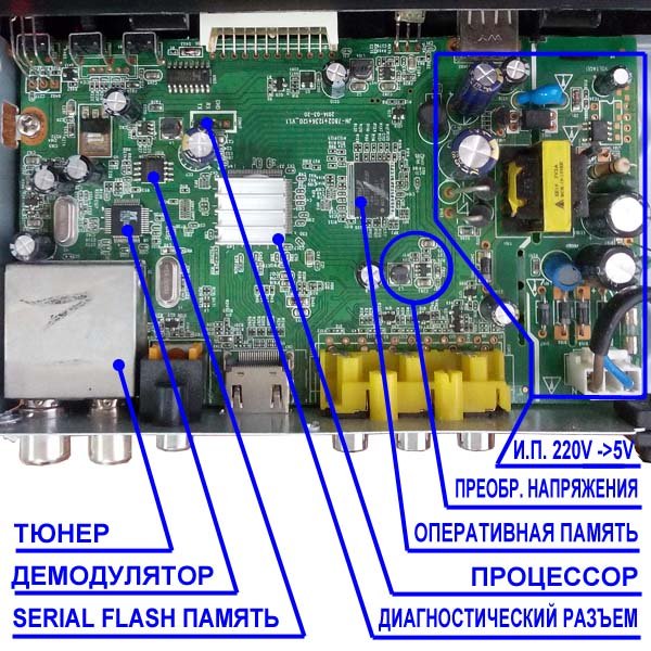
In detail: DIY repair of digital tuners from a real master for the site my.housecope.com.
Since the late 90s of the last century, audio - video technology has evolved greatly. From VCRs and DVD players, CD and MP3 recorders, to omnivorous media players that allowed you to read media files from a USB flash drive. Such devices cost 3-4 thousand in due time.
Now every DVB-T2 receiver can do it. The receivers are quite cheap - from 900 rubles, and in addition to reading media files from a flash drive, they allow you to watch television with digital quality for free, albeit only 20 channels. And everything would be fine if the Chinese, in pursuit of cheap devices, did not put low-quality parts there. I have had cases when in a receiver with a built-in power supply, after 2 years of operation, a small electrolytic capacitor had an overestimated ESR.
Shallow electrolytic capacitor
And accordingly, the receiver did not turn on, after measuring the equivalent series resistance ESR with a meter, and replacing the three-ruble capacitor, everything returned to normal and the receiver turned on. But this, as they say, was just lucky. More often, DC-DC converters burn out in receivers. Sometimes, fortunately for the user who decides to repair the set-top box on his own, stabilizers with 3 legs are installed instead, the replacement is not difficult, but sometimes the boards have unreliable five-legged converters, we will analyze this case. There are 3 of them - small microcircuits in the SOT-23-5 package.
Chip Converter - drawing
They give respectively 3.3 volts to power the RAM microcircuit, 1.8 volts and 1.2 volts to power the processor.
| Video (click to play). |
Dimensions of converter chip
It is easy to determine where the output of the microcircuit is, even without a datasheet for this microcircuit, the output of the converter is connected by a track with a choke necessary for the operation of the converter. You can familiarize yourself with one of the typical converter circuits by looking at the figure below:
Converter wiring diagram
What if your set-top box refused to turn on, you opened it and, having called, found two or more terminals in a short circuit or low resistance? Such converters, due to the fact that their binding is sometimes individual and incompatible with other types of converters, it is necessary to change them strictly to exactly the same, or in extreme cases to full analogs taken from datasheets.
Converter chip pinout
The wiring diagram, the ratings of the parts, the output current, and of course the output voltage must completely match. I got one of these attachments for repair with a 3.3 volt converter power input punched to the ground. A quick search in the radio stores of our city showed that we have no such microcircuit or complete analogs anywhere else.
Converter to Ali Express Party
And on Aliexpress, they were only in batches of at least 10 pieces, and with expensive paid delivery, which did not suit me. How to be in such a situation? The solution was found and I decided to share it with the readers of this site. Moreover, the output is very low-cost, in terms of the cost of parts in comparison with the purchase of a batch of converters.
Photo converter board
The fact is that for design on arduino and microcontrollers, special small-sized converters, stabilizers are produced in China, immediately with the necessary body kit soldered on the board for their operation. These are AMS1117 stabilizer microcircuits familiar to many electronics engineers.
Stabilizer ICs AMS1117
These microcircuits are produced as adjustable, which is unnecessary for us in this case, and with a fixed voltage at the output, but we are interested in voltages of 1.2, 1.8, 3.3 volts. For all these voltages, ready-made converter shawls are on sale on Aliexpress, based on these stabilizers. How can you distinguish between converter boards, if, for example, you bought them earlier and forgot what voltage they are?
On the case of microcircuits, in addition to the name of the model, stabilizers for a fixed voltage, it is sometimes written the voltage that will be at the output of the converter, that is, the same 1.2, 1.8, 3.3 V we need. How to place these converters in the receiver case? They will not take up much space, I would not think long, MGTF soldered to three of the contacts on the converter board, there are 4 of them: input plus power supply, output plus power supply, and two contacts common for input and output ground.
Why we use three contacts out of four I think it is clear. How can we check ourselves whether we found the correct pinout of the microcircuit if a Chinese datasheet found for example raises doubts? Call the output indicated by the datasheet Vin, often if the set-top box comes with an external power supply, it is directly connected to the power socket. Also, between the ground and the power input, an electrolytic capacitor is often installed on the board, at 220 μF x10 or 16 volts.
Condenser 220 x 25 volts
The plus of the capacitor is connected to the power input of the converter microcircuit. What if you do not know for what voltage this converter was at the output, that is, for what voltage do you need to buy the converter? You can try after dismantling the burned-out microcircuit and cleaning the contacts on the board from solder, supply power to the receiver and measure the supply voltage on the two remaining converters. And determine the voltage at the output of the remaining microcircuit by the elimination method. Solder this burnt-out converter using a hot air gun, or by applying a drop of solder, Rose or Wood's alloy to all contacts, and heating them quickly alternately with a 25-watt soldering iron.
If you are sure that the converter has burned out and are not afraid to burn it with the high temperature of the tip, during dismantling, you can apply a little POS-61 ordinary solder to all the contacts and alternately heat the 40-watt terminals with a soldering iron, trying to move the microcircuit. If, after soldering, it turned out that the short circuit was “underfoot” on the board, and not in the microcircuit, you need to finally make sure of this, clean the contacts of the old soldered converter from solder using a dismantling braid, applying an alcohol-rosin flux to the contacts with a brush (SCF).
SKF alcohol rosin flux
Then just put the braid on top of the contacts and heat the leads over the braid with a soldering iron. The solder will go to a clean braid. The tip of the braid can even be dipped in alcohol rosin flux for better absorption. As the solder is absorbed, the end of the braid should be cut and repeated from the beginning. The same should be done with the contacts on the board left after the soldered converter.
There, as usual, we will have "snot" from the solder applied during dismantling - they must be removed. Then you can solder the MGTF wire connected to the contacts of the converter, finding by the datasheet for this microcircuit where we have the power input, where is the output, and where is the ground. It will be possible to check, as I wrote above, the contact connected to the ground by the minus of the power supply, we can call by touching either the polygon on the board, or if you are a beginner and are not sure of the correctness of the dialing - the metal body of the USB connector.
After everything has been soldered, do not rush to turn on the attachment to the network, wash off the traces of the flux with alcohol, especially if you never know, used a weakly active flux, which in this case is a prerequisite for the long operation of the device.Then look under a strong magnifying glass or take a picture with a phone with a good camera and make sure not to put "snot" on the adjacent contacts, as they are there quite close to each other.
Multimeter in audible dial mode
To be completely sure that there is no short circuit, or if it was not possible to find a strong magnifying glass, ring all adjacent contacts relative to each other for a short circuit with a multimeter in the audible dial mode. All these procedures with replacing the converter make sense only in one case - if, after checking the datasheet, you did not find a short circuit of the power input pins to the power output, since in this case your processor or RAM microcircuit has already burned out due to the supply of an overestimated supply voltage.
DVB-T2 tuner board processor and memory
Which, of course, is sad, since then it will not be realistic to fix it either at home, or even in a good workshop, due to the laboriousness of the repair and its high cost - higher than the cost of a new attachment, it will not make sense.
Any more or less trained radio amateur can easily cope with this repair, and due to the low cost of the board for replacing the converter, it can be recommended as a means, albeit a "collective farm", but a very budget solution, in the absence of extra funds from an economical radio amateur for purchase of a new set-top box. Or there is simply a desire to prove to oneself that the repair of complex digital equipment is quite realistic sometimes to be carried out on our own. Successful repairs to everyone! AKV.
The most common malfunction of digital television set-top boxes is the failure of the power supply. In such an unpleasant case, it is very good if the model of the set-top box was with an external adapter, bought a new one and look further! And if not! And the power supply was built into the box itself? Then you have to repair or purchase a new one. But maybe there is an easy way out!
Hello dear readers! In this article, I want to share one simple repair method that anyone who knows how to hold a screwdriver and a soldering iron can do! Moreover, it is not necessary to master these tools masterfully.
I'm also not going to tell you anything overly complicated in the field of electronics repair, this is the lot of professionals. On the contrary, I will try to describe everything in such a way that even a non-specialist could cope and eliminate this malfunction.
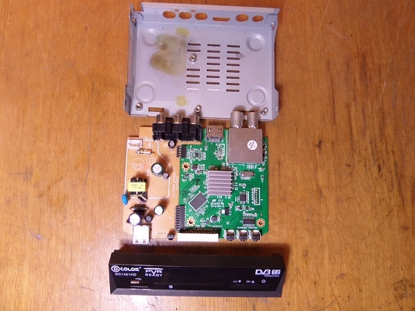
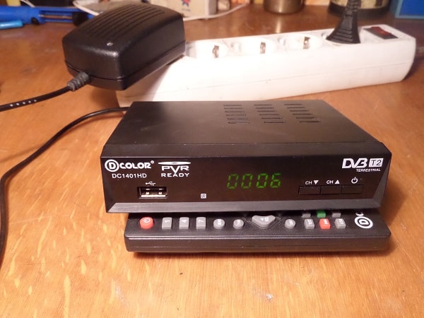
I'll make a reservation right away that this method is not suitable for all models of consoles, but for many, since they are often made according to a scheme very similar for this case. Everything will be based on a specific example of a set-top box from the D-Color company, namely the DC1401HD model. So by understanding this "high technology" you can repair your digital TV box yourself.
Fast navigation through the article
What is a sign that it is the power supply unit that has failed in the console, and not something else? If the set-top box connected to the outlet does not show any signs of life, neither the digital indicator nor the LED on the front panel is lit, then with a probability of 99% the reason is in it, in the power supply.
If, at the same time, the warranty period has already expired, then you can safely do the disassembly. As the experienced masters say, "An autopsy will show" I think you will deal with this part of the work without a detailed description, just be careful, usually two screws on the back wall, sometimes also on the sides allow you to release and open the top cover. Plastic latches on the sides and bottom hold the front panel, and the board itself is also fixed with screws to the bottom of the case and in the area of the connectors on the back of the case.
So, the set-top box is disassembled, the power cord is also removed from the connector, it is no longer needed. On the bottom of the case you can see traces of a "fire" that left behind a burnt-out power supply unit.
P.S. The power supply unit here is not a separate unit, as you might think from the name, but the section of the board on which the radio elements are located, providing the required power supply voltage for the set-top box.
I will outline the general picture, and for those who are already a little versed in radio engineering, this will already be enough to grasp the basis of the idea and repeat. So, the power supply circuits of this set-top box give out only one voltage - 5 Volts. Since this circuit has burned out and repair may be impractical (in terms of the total cost of radio components and repairs), that is, a simple solution. Replace the internal power supply with an external one. It's not very difficult!
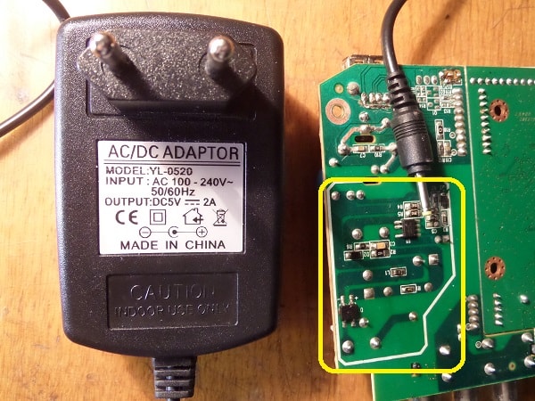
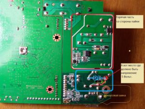
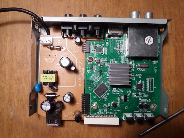
In the photo above, with a yellow frame, a section of the power supply unit that has failed is highlighted. The board has already been washed, so no traces of burning are visible. By the way - Among the repairmen, the expression "Burnt out" does not always mean literal burning with charring and other similar manifestations, it only means that the radio components are out of order.
For our repair, you will need to purchase an external power supply with an output voltage of 5 Volts and capable of delivering a current of 1.5 or better 2 Amperes. Now there are a lot of similar ones and can be purchased not expensively, or maybe you have a similar one, for example, an unused charger from a tablet or smartphone.
When a suitable adapter is available, it remains to find the desired point on the set-top box board and, observing the polarity, apply voltage to it from the external power supply. Everything! It remains to lay and secure the wire, or you can organize a detachable connection, as you like. I think the basics are clear, let's get down to the details.
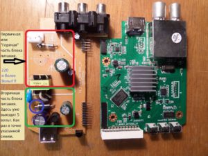
Just a little bit of basics for those who are not in the subject, so that you can figure it out. Pay attention to the photo. Click to enlarge.
In short, the power supply consists of:
- The primary "Hot" part - Hot, it is called because it is dangerous, connected to the mains voltage of 220 volts. Please note that even after unplugging from the outlet, for some time, there is a charge that can bring brr .. 😯 unpleasant sensations if you climb there. But in our case there is no need to climb there and we will not connect it to the outlet either.
- Secondary part - Safe there, there is a galvanic isolation from the mains. In the given example, at the points indicated in the photo, a voltage of only 5 Volts comes out from the rectifier diode.
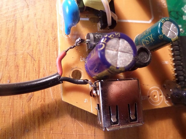
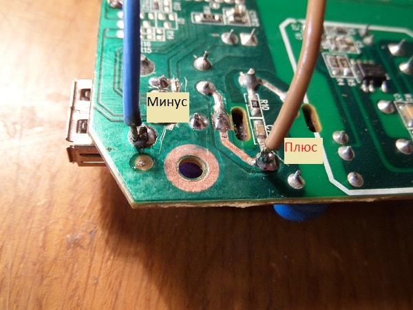
In the purchased, external power supply (at least 1.5 amperes, 5 Volts.) We bite off the plug, clean the ends of the wires and, having determined the polarity, we solder them: Positive to the diode terminal, on the side where the strip is drawn on it, and the negative to the common bus - the body of the USB port will be a convenient place for this. If you do not know how to determine the polarity, even without a device, see additional materials at the end of the article.
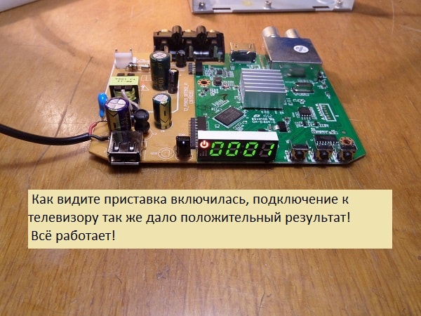
We connect the new power supply to the network, take it out of standby mode, check what happened.
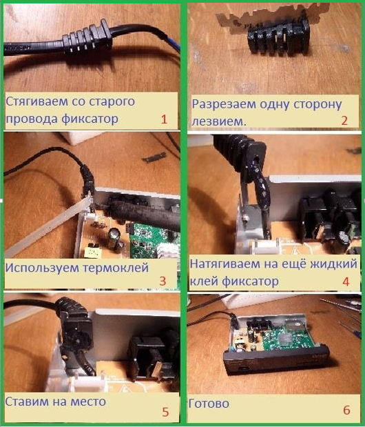
All OK! It remains to lay and secure the wire so as not to accidentally pull it out, collect everything in a heap and use it. In the end, it will look like this.
If you need ideas on how to attach the wire to the box? How to determine polarity without a device? Or how to solder the wire from the bottom of the board? - Then these additional materials are further in the text.
For those who have a multimeter, it will not be difficult to determine the polarity of the power supply, but what about those who do not have this device?
There are several simple ways:
- You can determine the polarity by the color of the wires. There is a rule - the Red wire is a plus, respectively, the other wire is a minus. This is almost always the case! Nearly! Sometimes there are exceptions, either the wires do not understand what color, or the rule has been violated. 😆
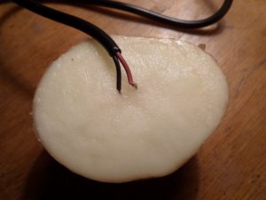
- There is another way, it will be needed - just don't laugh ... potatoes. Yes, yes, raw potatoes! The method is as follows. Cut the potato in half and stick the bare copper wires from the external power supply into it, at a distance of about 5 mm from each other. We plug the PSU into an outlet and wait. With the adapter voltage of 5 volts, it took about three minutes for a visible result. Click on the photo to enlarge.
The potato around the positive wire begins to turn green, so you can accurately determine the polarity without instruments.
In the first, simplest version, the wires were soldered from above, directly to the terminals of the radio components, but you can do it a little differently, run them from the bottom.
In this case, the wire to the case will pass under the board, from the bottom.
On this occasion, hastily prepared a small photo report with a short, step-by-step description of the actions. Hopefully this will be enough.
By the way! Such alteration can be arranged in order to adapt the digital set-top box for use in a car. You just need to use a 5 volt 2 ampere car adapter.
That's all! Success to everyone! I would be glad if this information helps you with something!
Satellite TV is not the last in the entertainment industry. And this is facilitated by the inexpensive price of equipment and an extensive list of channels. But all the joy can descend to "no" if the satellite TV receiver does not turn on.
This article will provide simple and practical ways to identify a faulty part in a tuner power supply. Although the methods are simple, their use in most cases allows you to repair the power supply of a satellite TV receiver with your own hands.
So, if your satellite TV receiver of the model: Gione, Cosmo Sat and the like has stopped working, then do not rush to worry, perhaps everything is not so bad. Try to find the cause yourself without the help of specialists.
What might you need? Multimeter, dial tone, soldering iron and a little patience.
We remove the cover of the device, and we see a free-standing module. This is a switching power supply. To start troubleshooting, remove it by unscrewing the screws and disconnecting the connector on the system board. Now the board is in front of us.

The first thing to do with the board is to visually determine if there are damaged (swollen) capacitors and other circuit elements. Often it is for this reason that the satellite TV receiver does not turn on.
If no damage is visible, then it is necessary to check the integrity of the cord and fuse. We put a dial on the ends of the fuse, and by the reaction of the device we determine its integrity.
Now, if in the circuit, when turned on, there is a short circuit, then the lamp will simply light up at full heat, without causing any harm to the circuit. If the lamp does not light up when turned on, we take a multimeter and measure the voltage across a large capacitor of 47 μF * 400 volts.
The diodes have been replaced, now we turn it on again and measure the constant voltage across the same capacitor. It should be, as mentioned above, about 300 volts. If this is the case, then the next step in the diagnosis is to measure the alternating voltage on one of the primary windings of the transformer. How to do this can be seen in the photo below.
When the device shows the presence of a pulsating AC voltage on the primary winding, it is necessary to immediately measure the DC voltage at the output of the unit.


 To do this, put the multimeter in the "DC voltage measurement" mode and connect the negative (black) probe to the second slot on the connector. This is a common (negative) contact. With the other end of the device, we alternately measure the voltage at the slots of the connector.
If you turn the plug with the slots towards you, and measure from left to right, then the voltages should be as follows:
If there is no voltage, then we do the same operation with the diodes of the secondary circuit, as described above. Having identified the faulty one, we replace it. Note the larger diode. It is labeled SR-360 and the like. He most often fails. Replacing it, you can solve the problem when the satellite TV receiver does not turn on. Again we measure the voltages at the terminals.
If this method did not give anything, then most likely the microcircuit in the primary circuit, which plays the role of a high-frequency alternating voltage generator, "flew out". But, as practice shows, this rarely happens.
That's all that I wanted to tell you about the repair of the power supply unit of the satellite TV receiver. Successful renovation.
49,235 total views, 30 views today
In this article, we will fix the most common breakdown in a satellite receiver, namely, we will repair the power supply of this device. Why a power supply? Yes, because in 95% of cases of failure of the receiver, the power supply is the culprit. The receiver may not turn on at all, it may turn on "halfway" (for example: the red indicator is on, and the green one, despite our efforts when pressing a certain button, does not turn on and there are many more signs), or some function may not work. And the reason for all these misunderstandings, in most cases, can be the power supply. We will repair the SVEC receiver, but functionally, on most of these devices, the power supplies differ only in the shape and location of the radio elements. The principle of repairing receivers is almost always the same.
So, let's begin. To begin with, of course, you need to disassemble our "unit". We unscrew the screws or bolts on the sides of the cover and remove it. We are presented with the following picture:
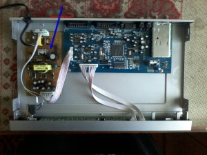
Now we will visually inspect the unit and the board for the visible reasons for the breakdown (this can be "swelling" of capacitors, burnout of the board or individual elements, etc.). If no apparent reason is found, then we look at the fuse. Even if it is not visually visible that the fuse has "blown", it is better, nevertheless, to check its integrity with a device. If the fuse is not working, do not rush to change it and try to turn on the receiver.Usually they just do not "burn out", on the contrary, for the most part, with overvoltage in the network, they remain unharmed, and something else must fail. This is how modern technology works. In general, we need to remove the power supply (in the figure it is marked with a blue arrow) from the receiver in order to check other items.
First of all, you need to check the power capacitor: there may be a residual charge in it. If there is a charge in the capacitor, it is imperative to discharge it, otherwise, when checking other radioelements, we can not only "burn" the device, but also get a good electric shock, albeit not fatal, but still unpleasant.
After that, we proceed to check the main transistor, which stands on the radiator. If we discard all professional terms, then we simply "ring" him for a "short circuit". These transistors are constantly failing, they are designated like this: D13009K. The literal values can be different, but the numerical values must be the same. This transistor is found in many receivers, but not all. In others, there are similar ones or there may be microcircuits. This is not the point, it is important that in most cases, it is the power transistors or microcircuits that fail.
On our power supply, after checking this transistor, a short circuit was found between its contacts. It follows from this that the transistor is "burnt out".
Now we need to unsolder it and check the rest of the radioelements. I will explain the check in a simple way: you need to check all the transistors and diodes (zener diodes) for a "short circuit".
All parts marked with arrows in the picture must be checked for "short circuit". After such a check, I found a "burnt out" diode, which is powered by 5V. We also need to solder it, so that, like the transistor, we can replace it with a usable one.
Next, we solder the new transistor and diode into place. Then you can check our power supply. We do it like this: insert it into the receiver and connect only the power cord and the power button to it. We DO NOT connect the loop with wires that goes to the board with processors. We will check by the output voltages, the value of which is indicated on the power supply, near the "socket" where the loop is inserted.
We measure the voltages at the output of the power supply and, if they coincide with the values on the board, you can connect a loop.
Everything. Now we fasten all the bolts that attach the power supply to the receiver and close our device with a lid. Ready.
Of course, the most common and not difficult type of breakdown is described here. There may be more serious reasons for the failure of this device. Then, without the intervention of a specialist, it is impossible to do, but without doing anything, it is impossible to learn something.
Thank you. Very interesting article. Everything is clear and simple.
Thank you for your feedback and participation in the life of the site!
Hello, I have such a problem, the receiver turns on, but when the cable is connected from the WORKING antenna, there is no signal or quality. I opened the receiver. Not one condenser is swollen, what could be the problem?
I only repair power supplies in receivers, but I don’t climb into the main board, so I can’t help. But I can assume that this is a tuner or firmware.
Hello Victor, I have such a problem. I got the same svec A8 receiver as a gift. The power supply unit was not in working order. The D13009k transistor failed, I replaced it with J13009k and the power supply unit came to life, but it turned out that the U5 transistor was missing on the main board. Could you please write and photograph its marking. I would be very grateful for your help.
Hey! U5 is an LM317 regulator, the same as U24.
Hey! Thank you so much for your reply. And then I climbed the whole Internet and did not find a scheme from him. I will solder and try to run.
Hello. Globo 4100c the red indicator flashes when the button is pressed up lights up 8. Visually, everything is in order in the power supply unit. What should be changed first in it?
Hey! Check the output voltages from the power supply, the stabilizers on the main board.
Hello. There is an Orton 4050c tuner. After disconnecting from the network, it did not start.The display shows a flashing red light and flashing numbers. Having disassembled, I did not find any swollen canders. But I found out bad soldering (something was wobbling, something just fell off when I touched it) Soldered. I measured the output voltages on the removed BC. There is. 3.3v. 5v. 12v. 22v. True, my DT-832 tester shows slightly overestimated readings (3.5v 5.5v 14.3v 24.2v). But when connected to the board, 3.3v and 5v disappear. The display turned off. The same. I can't figure out where to dig. Can anyone help. Thanks in advance.
Hey! Look at the stabilizers on the main board.
Zdrastvujte.pomagite pocinit resiver VU SOLO 2SE posle grozi nevkliucajetse.bp pocinil.kogda nazimaju na knopku vkliucenija na resivere lampa nemnogo jarce svetitse otpuska mozu opju shezet jarce svetitse otpuska mozu opju shezet jarce svetitse otpuska mozu opju shezet jarce svetitse otpuska mozu opju shezet jarce u.
After a thunderstorm, the processor usually crashes or the firmware flies.
na usb portah net 5 volt.prosit nepolucajetse.
You must be logged in to post a comment.
This site uses Akismet to combat spam. Find out how your comment data is processed.
Satellite equipment is also technology. And any technique, as you know, breaks down.
A satellite receiver is a receiver that is quite complex in its addition and a circuit may be needed to repair it. Rather, in most cases you cannot do without it. Here I will lay out the diagrams for satellite tuners.
Sometimes I have to look for circuits for receivers, so I decided to post it here, maybe someone else will need it.
I think over time to save up a large collection. You can join before the process.
Download schematics for receivers GLOBO 4100s, 5000, 7010a download
Download schematics for receivers OPENBOX F-100, F-300, X-600, X-610, X-620, X-800, X-820CI
Download schematics for receivers CosmoSat 7400, 7405, 7410, power supply unit СosmoSat-7100 download
Download schematics for receivers DRE-4000, 5000, 5000 rev 3.1 download
Download schematics for receivers SAMSUNG 9400, DSB-B150F, DSB-S300V, DSR-9500FTA / CI / EM VIA / VIA CI download
Download circuits for receivers HUMAX F1-VA, F1, F1-CI, F1-VA, F1-VACI download

