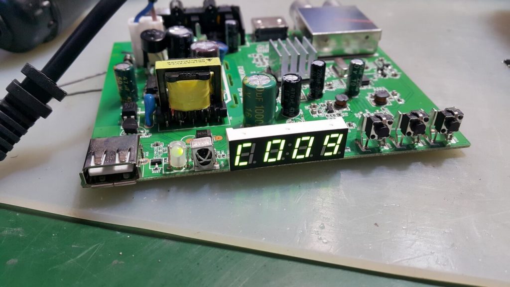
In detail: DIY repair of the t2 tuner after a thunderstorm from a real master for the site my.housecope.com.
Since the late 90s of the last century, audio - video technology has evolved greatly. From VCRs and DVD players, CD and MP3 recorders, to omnivorous media players that allowed you to read media files from a USB flash drive. Such devices cost 3-4 thousand in due time.
Now every DVB-T2 receiver can do it. The receivers are quite cheap - from 900 rubles, and in addition to reading media files from a flash drive, they allow you to watch television with digital quality for free, albeit only 20 channels. And everything would be fine if the Chinese, in pursuit of cheap devices, did not put low-quality parts there. I have had cases when in a receiver with a built-in power supply, after 2 years of operation, a small electrolytic capacitor had an overestimated ESR.
Shallow electrolytic capacitor
And accordingly, the receiver did not turn on, after measuring the equivalent series resistance ESR with a meter, and replacing the three-ruble capacitor, everything returned to normal and the receiver turned on. But this, as they say, was just lucky. More often, DC-DC converters burn out in receivers. Sometimes, fortunately for the user who decides to repair the set-top box on his own, stabilizers with 3 legs are installed instead, the replacement is not difficult, but sometimes the boards have unreliable five-legged converters, we will analyze this case. There are 3 of them - small microcircuits in the SOT-23-5 package.
Chip Converter - drawing
They give respectively 3.3 volts to power the RAM microcircuit, 1.8 volts and 1.2 volts to power the processor.
| Video (click to play). |
Dimensions of converter chip
It is easy to determine where the output of the microcircuit is, even without a datasheet for this microcircuit, the output of the converter is connected by a track with a choke necessary for the operation of the converter. You can familiarize yourself with one of the typical converter circuits by looking at the figure below:
Converter wiring diagram
What if your set-top box refused to turn on, you opened it and, having called, found two or more terminals in a short circuit or low resistance? Such converters, due to the fact that their binding is sometimes individual and incompatible with other types of converters, it is necessary to change them strictly to exactly the same, or in extreme cases to full analogs taken from datasheets.
Converter chip pinout
The wiring diagram, the ratings of the parts, the output current, and of course the output voltage must completely match. I got one of these attachments for repair with a 3.3 volt converter power input punched to the ground. A quick search in the radio stores of our city showed that we have no such microcircuit or complete analogs anywhere else.
Converter to Ali Express Party
And on Aliexpress, they were only in batches of at least 10 pieces, and with expensive paid delivery, which did not suit me. How to be in such a situation? The solution was found and I decided to share it with the readers of this site. Moreover, the output is very low-cost, in terms of the cost of parts in comparison with the purchase of a batch of converters.
Photo converter board
The fact is that for design on arduino and microcontrollers, special small-sized converters, stabilizers are produced in China, immediately with the necessary body kit soldered on the board for their operation. These are AMS1117 stabilizer microcircuits familiar to many electronics engineers.
Stabilizer ICs AMS1117
These microcircuits are produced as adjustable, which is unnecessary for us in this case, and with a fixed voltage at the output, but we are interested in voltages of 1.2, 1.8, 3.3 volts. For all these voltages, ready-made converter shawls are on sale on Aliexpress, based on these stabilizers. How can you distinguish between converter boards, if, for example, you bought them earlier and forgot what voltage they are?
On the case of microcircuits, in addition to the name of the model, stabilizers for a fixed voltage, it is sometimes written the voltage that will be at the output of the converter, that is, the same 1.2, 1.8, 3.3 V we need. How to place these converters in the receiver case? They will not take up much space, I would not think long, MGTF soldered to three of the contacts on the converter board, there are 4 of them: input plus power supply, output plus power supply, and two contacts common for input and output ground.
Why we use three contacts out of four I think it is clear. How can we check ourselves whether we found the correct pinout of the microcircuit if a Chinese datasheet found for example raises doubts? Call the output indicated by the datasheet Vin, often if the set-top box comes with an external power supply, it is directly connected to the power socket. Also, between the ground and the power input, an electrolytic capacitor is often installed on the board, at 220 μF x10 or 16 volts.
Condenser 220 x 25 volts
The plus of the capacitor is connected to the power input of the converter microcircuit. What if you do not know for what voltage this converter was at the output, that is, for what voltage do you need to buy the converter? You can try after dismantling the burned-out microcircuit and cleaning the contacts on the board from solder, supply power to the receiver and measure the supply voltage on the two remaining converters. And determine the voltage at the output of the remaining microcircuit by the elimination method. Solder this burnt-out converter using a hot air gun, or by applying a drop of solder, Rose or Wood's alloy to all contacts, and heating them quickly alternately with a 25-watt soldering iron.
If you are sure that the converter has burned out and are not afraid to burn it with the high temperature of the tip, during dismantling, you can apply a little POS-61 ordinary solder to all the contacts and alternately heat the 40-watt terminals with a soldering iron, trying to move the microcircuit. If, after soldering, it turned out that the short circuit was “underfoot” on the board, and not in the microcircuit, you need to finally make sure of this, clean the contacts of the old soldered converter from solder using a dismantling braid, applying an alcohol-rosin flux to the contacts with a brush (SCF).
SKF alcohol rosin flux
Then just put the braid on top of the contacts and heat the leads over the braid with a soldering iron. The solder will go to a clean braid. The tip of the braid can even be dipped in alcohol rosin flux for better absorption. As the solder is absorbed, the end of the braid should be cut and repeated from the beginning. The same should be done with the contacts on the board left after the soldered converter.
There, as usual, we will have "snot" from the solder applied during dismantling - they must be removed. Then you can solder the MGTF wire connected to the contacts of the converter, finding by the datasheet for this microcircuit where we have the power input, where is the output, and where is the ground. It will be possible to check, as I wrote above, the contact connected to the ground by the minus of the power supply, we can call by touching either the polygon on the board, or if you are a beginner and are not sure of the correctness of the dialing - the metal body of the USB connector.
After everything has been soldered, do not rush to turn on the attachment to the network, wash off the traces of the flux with alcohol, especially if you never know, used a weakly active flux, which in this case is a prerequisite for the long operation of the device.Then look under a strong magnifying glass or take a picture with a phone with a good camera and make sure not to put "snot" on the adjacent contacts, as they are there quite close to each other.
Multimeter in audible dial mode
To be completely sure that there is no short circuit, or if it was not possible to find a strong magnifying glass, ring all adjacent contacts relative to each other for a short circuit with a multimeter in the audible dial mode. All these procedures with replacing the converter make sense only in one case - if, after checking the datasheet, you did not find a short circuit of the power input pins to the power output, since in this case your processor or RAM microcircuit has already burned out due to the supply of an overestimated supply voltage.
DVB-T2 tuner board processor and memory
Which, of course, is sad, since then it will not be realistic to fix it either at home, or even in a good workshop, due to the laboriousness of the repair and its high cost - higher than the cost of a new attachment, it will not make sense.
Any more or less trained radio amateur can easily cope with this repair, and due to the low cost of the board for replacing the converter, it can be recommended as a means, albeit a "collective farm", but a very budget solution, in the absence of extra funds from an economical radio amateur for purchase of a new set-top box. Or there is simply a desire to prove to oneself that the repair of complex digital equipment is quite realistic sometimes to be carried out on our own. Happy repairs to everyone! AKV.
If your DVB-T2 digital set-top box for receiving terrestrial digital TV has stopped working, then in some cases you can solve the problem yourself. In this article, we will describe the most common problems that arise when using digital set-top boxes. You will also be able to determine if the viewing problems are a defect in the set-top box itself or the problem is in the antenna or TV.
This is one of the most common breakdowns of digital terrestrial set-top boxes. It manifests itself, as a rule, in two versions: the receiver does not show signs of life at all, or the red indicator of the standby mode is on, but the set-top box does not go into working mode. Most receivers start working immediately after plugging into the outlet and do not need to be turned on from the remote control. If this does not happen, then it is most likely that you have a faulty power supply.
The power supply is a weak point in any technique and digital set-top boxes are no exception. The power supply unit may fail completely - in this case, not a single indicator on the set-top box lights up at all and the device does not react in any way to the connection to the 220V network. But it often happens that the power supply unit produces an underestimated voltage or current. In this case, the tuner “tries to turn on” giving some signs of life, but does not go into operation mode.
Solution: If the power supply is external (as in the picture), then it is easy to solve this problem on your own. Power supplies for set-top boxes are usually standard and interchangeable, even of different models and manufacturers. You just need to make sure that the new power supply unit outputs a voltage of 5V and has the same plug at the end of the wire as the old one. You can buy it in specialized stores that sell antenna equipment. In most cases, you can ask your dealer to plug the power supply into your receiver and make sure the problem is resolved.
It is more difficult if the power supply is built into the console. The characteristic feature of the internal power supply unit is a regular plug at the end of the wire. In this case, the power wire is not disconnected from the set-top box itself, as is the case in the external version. In this case, it is best to contact a service center for repair.
This defect is quite rare, but if it is detected, repairing the receiver is most often impractical. A clear sign of such a malfunction: the appearance of image distortion and "freezing" of the picture, which appears 5-20 minutes after turning on the digital tunerafter which the problem persists.Similar symptoms occur with a weak signal from the antenna, but in the latter case, image distortions do not have a clear connection with the duration of the DVB-T2 receiver.
The problem may be the same power supply or processor overheating. If the power supply is external, you can try to connect another power supply unit. If not, then the matter is in the processor itself and the repair of the product in this case is inappropriate.
A thunderstorm has passed and the signal from the terrestrial antenna has disappeared. What happened? Why is there no signal in non-analog range not in digital t2? - you ask. The answer is obvious. Thunderstorm! Lightning discharges carry a static voltage that knocks out active antenna amplifiers, power supplies, digital set-top boxes t2, and sometimes the televisions themselves. Therefore, during a thunderstorm, it is recommended to turn off all devices from the 220V electrical network, and disconnect the antenna cable from the TV or T2 receiver. Ideally, of course, a lightning protection, a lightning rod with a good ground loop should be installed, but even these precautionary methods do not give a 100% guarantee against lightning striking the antenna.
Lightning protection, of course, is a good thing, but what to do if lightning still got your home.
First you need to understand what went wrong. We start by turning on the TV. If the TV turns on, it's already good, but it happens that the input receiving unit flies out. Suppose you have a t2 receiver installed that receives a digital signal from a decimeter antenna and transmits it to the TV - we also plug it into the 220v network and see if it turns on. The t2 tuner turned on, let's go further (turning on the TV and the t2 set-top box does not guarantee that one of them has not failed the receiving unit). Next, we check the performance of the antenna power supply by the same analogy as the previous two devices. The power supply has turned on, it's already good (if it did not turn on, replace the power supply). And at the end we check the amplifier board. Further, the speech will go for those who are friends with a soldering iron, if you are not like that, then just buy and replace the antenna amplifier with the same type as you had (swa 777, 999, 9999, 3501, 2000, 7777, etc. or for any similar in its characteristics)
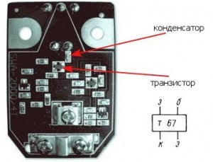
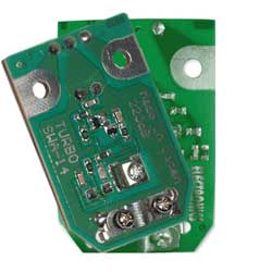
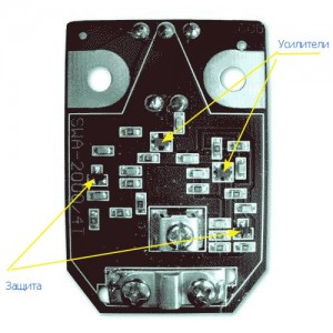
Consider the repair of terrestrial antennas from the repair of antenna amplifiers from the so-called "Polish antennas", using the example of an amplifier Eurosky SWA-2000 fig. 1
All amplifiers are a two-stage aperiodic amplifier based on microwave bipolar transistors, connected according to a circuit with an OE. For those who are friends with a soldering iron, I think it is not necessary to tell that the amplifier has two stages with decoupling along the power circuit, etc. Let's go straight to practice - during lightning discharges, the transistor of the amplifier of the first stage and the isolation capacitor, which are shown in the figure below, most often fail.
Successful repairs. And let Zeus take his lightning away from you! )
Is your TV, radio, mobile phone or kettle broken? And you want to create a new topic about this in this forum?
First of all, think about this: imagine that your father / son / brother has an appendicitis pain and you know from the symptoms that it is just appendicitis, but there is no experience of cutting it out, as well as the tool. And you turn on your computer, access the Internet on a medical site with the question: "Help to cut out appendicitis." Do you understand the absurdity of the whole situation? Even if they answer you, it is worth considering factors such as the patient's diabetes, allergies to anesthesia and other medical nuances. I think no one does this in real life and will risk trusting the life of their loved ones with advice from the Internet.
The same is in the repair of radio equipment, although of course these are all the material benefits of modern civilization and in case of unsuccessful repairs, you can always buy a new LCD TV, cell phone, iPAD or computer.And for the repair of such equipment, at least it is necessary to have the appropriate measuring (oscilloscope, multimeter, generator, etc.) and soldering equipment (hairdryer, SMD-hot tweezers, etc.), a schematic diagram, not to mention the necessary knowledge and repair experience.
Let's consider the situation if you are a beginner / advanced radio amateur who solders all sorts of electronic gizmos and has some of the necessary tools. You create an appropriate thread on the repair forum with a short description of “patient symptoms”, ie. for example “Samsung LE40R81B TV does not turn on”. So what? Yes, there can be a lot of reasons for not switching on - from malfunctions in the power system, problems with the processor or flashing firmware in the EEPROM memory.
More advanced users can find the blackened element on the board and attach a photo to the post. However, keep in mind that you replace this radio element with the same one - it is not a fact that your equipment will work. As a rule, something caused the combustion of this element and it could “pull” a couple of other elements along with it, not to mention the fact that it is quite difficult for a non-professional to find a burned-out m / s. Plus, in modern equipment, SMD radio elements are almost universally used, soldering which with an ESPN-40 soldering iron or a Chinese 60-Watt soldering iron you risk overheating the board, peeling tracks, etc. The subsequent restoration of which will be very, very problematic.
The purpose of this post is not any PR of repair shops, but I want to convey to you that sometimes self-repair can be more expensive than taking it to a professional workshop. Although, of course, this is your money and what is better or more risky is up to you.
If you nevertheless decide that you are able to independently repair the radio equipment, then when creating a post, be sure to indicate the full name of the device, modification, year of manufacture, country of origin and other detailed information. If there is a diagram, then attach it to the post or give a link to the source. Write down how long the symptoms have been manifesting, whether there were surges in the supply voltage network, whether there was a repair before that, what was done, what was checked, voltage measurements, oscillograms, etc. From a photo of a motherboard, as a rule, there is little sense, from a photo of a motherboard taken on a mobile phone there is no sense at all. Telepaths live in other forums.
Before creating a post, be sure to use the search on the forum and on the Internet. Read the relevant topics in the subsections, perhaps your problem is typical and has already been discussed. Be sure to read the article Repair strategy
The format of your post should be as follows:
Topics with the title “Help fix the Sony TV” with the content “broken” and a couple of blurred photos of the unscrewed back cover, taken with the 7th iPhone, at night, with a resolution of 8000x6000 pixels are immediately deleted. The more information about the breakdown you put in a post, the more chances you will get a competent answer. Understand that the forum is a system of gratuitous mutual assistance in solving problems and if you are dismissive of writing your post and do not follow the above tips, then the answers to it will be appropriate, if anyone wants to answer at all. Also note that no one should answer instantly or within a day, say, no need to write after 2 hours “That no one can help”, etc. In this case, the topic will be deleted immediately.
You should make every effort to find a breakdown on your own before you get stuck and decide to go to the forum. If you outline the whole process of finding a breakdown in your topic, then the chance of getting help from a highly qualified specialist will be very great.
If you decide to take your broken equipment to the nearest workshop, but do not know where, then perhaps our online cartographic service will help you: workshops on the map (on the left, press all buttons except “Workshops”). You can leave and view user reviews for workshops.
For repairmen and workshops: you can add your services to the map. Find your object on the map from the satellite and click on it with the left mouse button. In the field “Object type:” do not forget to change to “Equipment repair”. Adding is absolutely free! All objects are checked and moderated. A discussion of the service is here.
Message keyOption »23 Nov 2012, 23:24
Message Oleg Bondarenko »23 Nov 2012, 23:54
Unauthorized ad placement - ban and remove all ads and account.
Need help setting up your T2? Write a question on the forum.
Registration takes 2 minutes, the answer to the question is in brackets.
Message Polishchuk »26 Nov 2012, 14:10
Message layman »26 Nov 2012, 14:47
Message Orlean77 »26 Nov 2012, 18:16
Message kvv1103 »30 Nov 2012, 20:39
Message kvv1103 »30 Nov 2012, 20:42
Message Oleg Bondarenko »30 Nov 2012, 20:55
Unauthorized ad placement - ban and remove all ads and account.
Need help setting up your T2? Write a question on the forum.
Registration takes 2 minutes, the answer to the question is in brackets.
Message PONT-SEV »03 Sep 2013, 11:46
Message Oleg Bondarenko »03 Sep 2013, 13:36
Unauthorized ad placement - ban and remove all ads and account.
Need help setting up your T2? Write a question on the forum.
Registration takes 2 minutes, the answer to the question is in brackets.
Message PONT-SEV »03 Sep 2013, 13:49
Message Oleg Bondarenko »03 Sep 2013, 14:44
Unauthorized ad placement - ban and remove all ads and account.
Need help setting up your T2? Write a question on the forum.
Registration takes 2 minutes, the answer to the question is in brackets.
Message PONT-SEV »03 Sep 2013, 14:59
Message Oleg Bondarenko »03 Sep 2013, 18:10
Unauthorized ad placement - ban and remove all ads and account.
Need help setting up your T2? Write a question on the forum.
Registration takes 2 minutes, the answer to the question is in brackets.
Message PONT-SEV »03 Sep 2013, 18:48
It was being repaired in the wrong hands. Two input capacitors and TNY175 PN were exchanged for TNY276PN. Everything else is in place. It just might have jumped off the firmware during the update from the air. A person can turn off during the update. Warranty through Kiev, because it was received as Participant B, O, There is no question of any money for repairs. I just wanted to help, as usual. I looked at the external manifestations through a magnifying glass.
In satellite receivers, this is a common occurrence and is a power supply. I had to raise it through Jitah, that's why the thought arose about the firmware rally.
Read (and through JITAH) this is about the Russian language, otherwise they will not understand correctly again. Question. So where is this MOSFET In this receiver or this function is performed by TNY 175 PN.
Satellite TV is not the last in the entertainment industry. And this is facilitated by the inexpensive price of equipment and an extensive list of channels. But all the joy can descend to "no" if the satellite TV receiver does not turn on.
This article will provide simple and practical ways to identify a faulty part in a tuner power supply. Although the methods are simple, their use in most cases allows you to repair the power supply unit of a satellite TV receiver with your own hands.
So, if your satellite TV receiver of the model: Gione, Cosmo Sat and the like has stopped working, then do not rush to worry, perhaps everything is not so bad. Try to find the cause yourself without the help of specialists.
What might you need? Multimeter, dial tone, soldering iron and a little patience.
We remove the cover of the device, and we see a free-standing module. This is a switching power supply. To start troubleshooting, remove it by unscrewing the screws and disconnecting the connector on the system board. Now the board is in front of us.

The first thing to do with the board is to visually determine if there are damaged (swollen) capacitors and other circuit elements. Often it is for this reason that the satellite TV receiver does not turn on.
If no damage is visible, then it is necessary to check the integrity of the cord and fuse. We put a dial on the ends of the fuse, and by the reaction of the device we determine its integrity.
Now, if in the circuit, when turned on, there is a short circuit, then the lamp will simply light up at full heat, without causing any harm to the circuit. If the lamp does not light up when turned on, we take a multimeter and measure the voltage across a large capacitor of 47 μF * 400 volts.
The diodes have been replaced, now we turn it on again and measure the constant voltage across the same capacitor. It should be, as mentioned above, about 300 volts. If this is the case, then the next step in the diagnosis is to measure the alternating voltage on one of the primary windings of the transformer. How to do this can be seen in the photo below.
When the device shows the presence of a pulsating AC voltage on the primary winding, it is necessary to immediately measure the DC voltage at the output of the unit.


 To do this, put the multimeter in the "DC voltage measurement" mode and connect the negative (black) probe to the second slot on the connector. This is a common (negative) contact. With the other end of the device, we alternately measure the voltage at the slots of the connector.
If you turn the plug with the slots towards you, and measure from left to right, then the voltages should be as follows:
If there is no voltage, then we do the same operation with the diodes of the secondary circuit, as described above. Having identified the faulty one, we replace it. Note the larger diode. It is labeled SR-360 and the like. He most often fails. Replacing it, you can solve the problem when the satellite TV receiver does not turn on. Again we measure the voltages at the terminals.
If this method did not give anything, then most likely the microcircuit in the primary circuit, which plays the role of a high-frequency alternating voltage generator, "flew out". But, as practice shows, this rarely happens.
That's all that I wanted to tell you about the repair of the power supply unit of the satellite TV receiver. Successful renovation.
49,197 total views, 50 views today
Repair of antenna amplifiers
The repair of antenna amplifiers is usually caused by static electricity (lightning discharges) and a breakdown of the power supply (overvoltage, which rarely happens).
Antenna amplifier is damaged due to a thunderstorm.
Look at the figure with the SWA-2000 amplifier, it shows the transistors involved in amplification and protection (of little help and installed in amplifiers of the 2000 series and above). In case of lightning discharges, the transistor of the amplifier of the first stage and the isolation capacitor most often fail, see Fig.

When repairing antenna amplifiers in the first stage, it is advisable to install high-frequency transistors with an F boundary of 1.5 -2 -3 GHz and a low level of intrinsic noise - Ksh, for example, transistors KT391A-2, KT3101A-2, KT3115A-2, KT3115B-2, KT3115V- 2, the noise characteristics of most amplifier models does not deteriorate, and the use of transistors 2T3124A-2, 2T3124B-2, 2T3124V-2, KT3132A-2 reduces Ksh to 1.5 dB, which improves the parameters of the amplifier. This circumstance allows us to recommend replacing the first transistor of the amplifier with those indicated by the latter, even in serviceable, but "noisy" amplifiers in order to improve the quality of their work. In the second stage, you can use cheaper and more powerful transistors KT391A-2, KT3101A-2 and even the series KT371, KT372, KT382, KT399, KT316 and others with a cutoff frequency of about 2 GHz.
If there are difficulties in repairing, in acquiring such transistors, then you can put the widespread KT399, KT316 in the first and second cascades, while there will be no noticeable deterioration of the picture.
It is better to install new transistors on the opposite side of the board, pre-drilling holes for the terminals with a drill with a diameter of 0.5 ... 0.8 mm. It is better to drill so that the hole touches the edge of the platform.
In SWA amplifiers, both transistors operate with a collector current of 10 ... 12 mA. Such a current is acceptable for the second transistor, but constantly exceeds the allowable one for the first, if transistors of the KT3115, KT3124 and KT3132A-2 series are installed. Therefore, after mounting a specific instance, it is necessary to set the operating point of the transistor VT1. To do this, the microresistor R1 is evaporated and instead of it, a trimmer resistor with a resistance of 68 ... 100 kOhm is temporarily connected. Before turning on the power, the resistor slider must be in the position of maximum resistance so as not to damage the transistor. The amplifier is supplied with a voltage of 12 V from the power supply and the voltage drop across the resistor R2 is measured. By dividing the measured voltage by the resistance of the resistor R2, the collector current is recognized. By adjusting the resistance of the trimmer downward, a collector current of about 5 mA is achieved, which corresponds to a minimum of noise in the characteristics of transistors. Further, instead of a trimming resistor, a constant of the same resistance is soldered.
After that, the printed circuit board and transistors are coated with a layer of radio-technical varnish or a compound to protect it from moisture.
How to avoid such breakdowns, read the article "Why did the antenna amplifier burn out?"
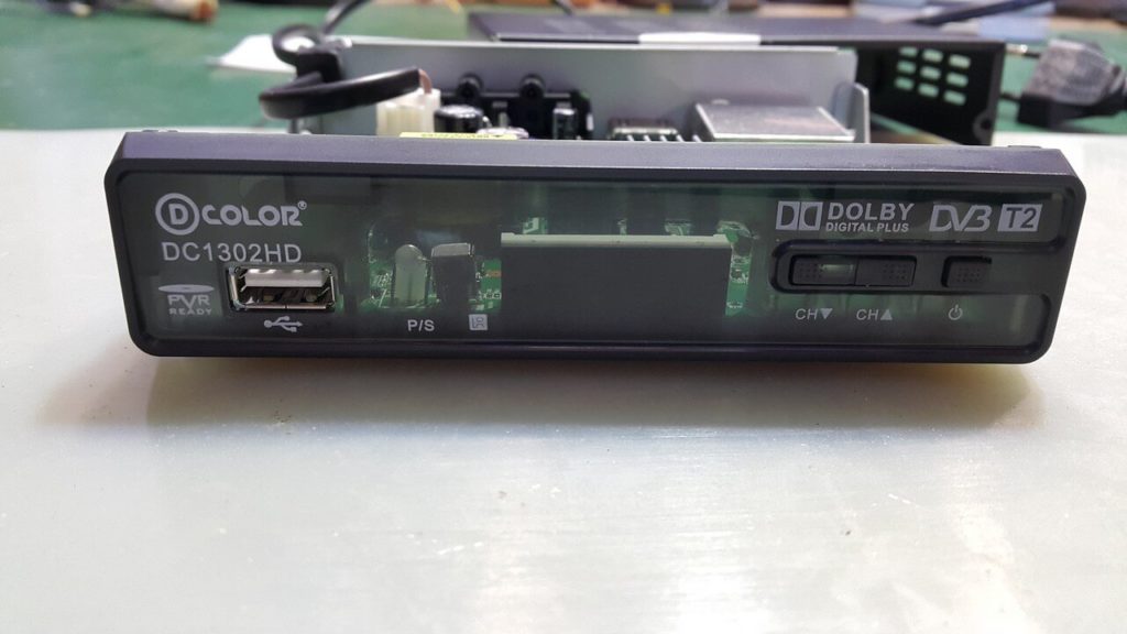
Hello everyone. Today they brought the receiver after a thunderstorm DVB-T2 Color DC1302HD with a malfunction does not turn on, as the client said that there was a thunderstorm and knocked out plugs in the electricity meter and after turning on the light the receiver no longer worked.
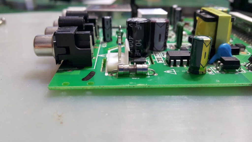
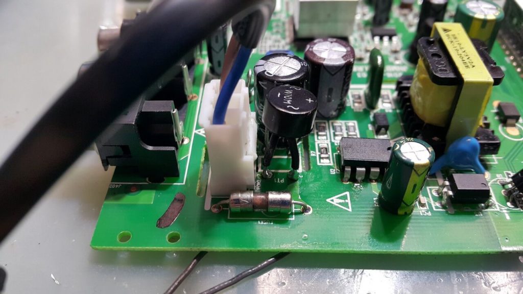
We take the board out of the case and visually inspect it. After examining the receiver, a blown fuse was found, this can happen for two reasons, it is a faulty diode bridge or a PWM controller.
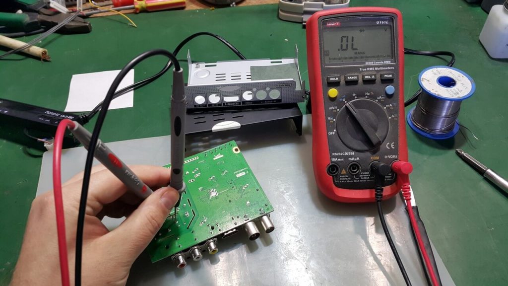
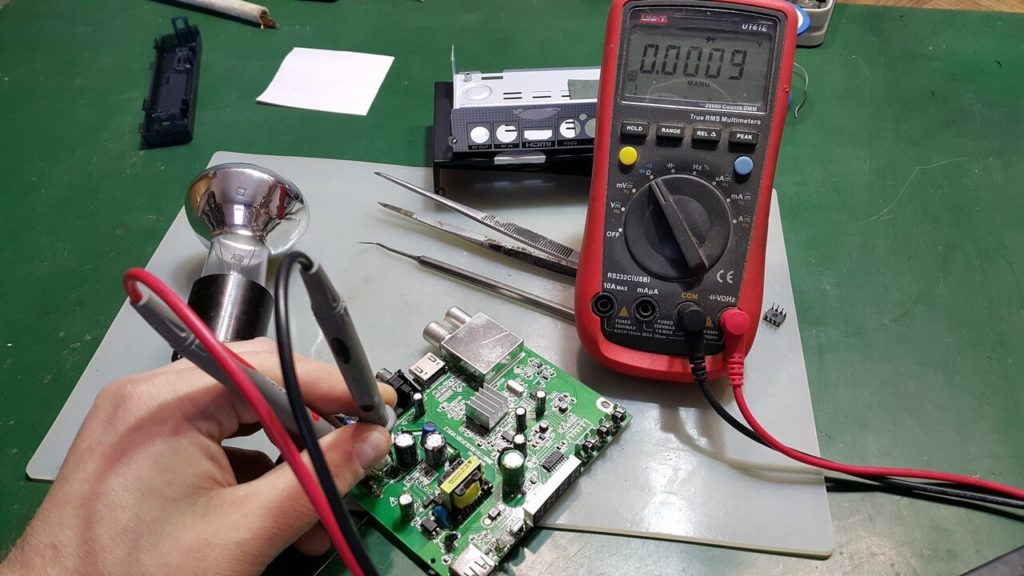
For further troubleshooting, you need to check the primary power circuits. We install the tester probes on the network capacitor and check for a short circuit. As you can see in the photo, we do not have a short circuit.
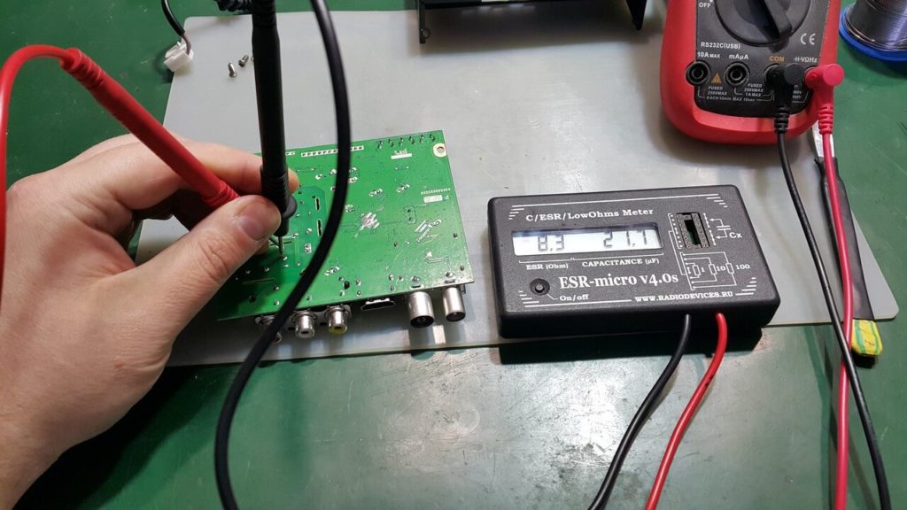
Next, we check the integrity of the network capacitor, it may fail due to overvoltage, the capacitor is alive.
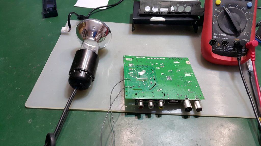
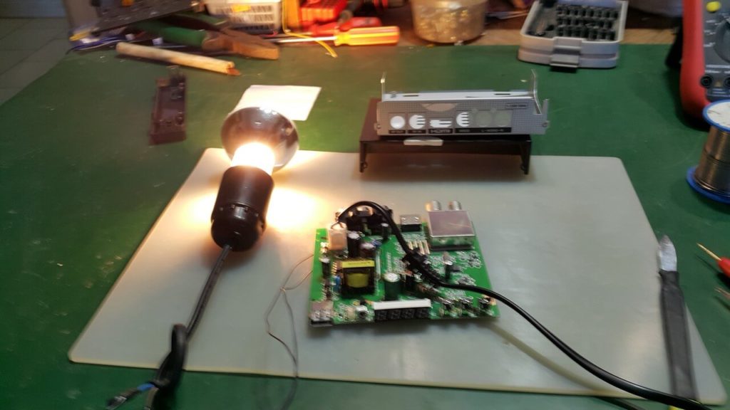
In order to plug the receiver into an outlet and check how it behaves, I installed a 40-watt incandescent lamp in the fuse place so that we would not have fireworks.
After plugging into the outlet, our light is constantly on - this means that there is an overload in the primary circuit.
Next, we check the diode bridge, I did not immediately think to check it and immediately dropped the PWM controller, here the LY2117 is installed, another Chinese hack, I could not even find a PDF on it, but let's not be distracted. As it turned out, we have a diode bridge in a short circuit, most likely in it is the problem of a blown fuse.
I installed a diode bridge W10M here is a datasheet, I could not find a suitable one to install here anymore.
Next, change the 2 amp 250 volt fuse and turn on the receiver.
All repairs are over, we assemble the receiver and install it for testing.
And not this happens with technology, here's a little sarcasm or humor ...
A young lady, about 18 years old ... on a laptop she can't connect to WiFi. Of course, I see the WiFi icon in the right corner, but I'm kidding.
Do you know where the proxy settings are here? I asked hopefully.
I received no answer. You might as well have asked her ... Can you tell me how I can reticulate splines using a hexagonal decoding system so that I can create a GUI in VisualBasic and trace the IP address?
It's just ... a lot of cases are just like clicking the WiFi icon.
And so we continue with a smile (but seriously):
When plugged into an outlet, the receiver does not turn on:
> Check if the switch on the rear panel is in the off position
> If the switch is in the on position and the satellite receiver does not turn on, the receiver's power supply unit will need to be repaired.
If the receiver hangs when loading, boots but does not respond to the remote control, there is no ftp access.
> It may not be trite, but the reason may be in one of the installed plugins.
When you turn on the satellite receiver, the “boot” message appears on the receiver screen and nothing happens:
> Your receiving equipment has a software failure, the receiver will need to be re-flashed
> The motherboard on your satellite receiver is out of order.
When the satellite receiver is operating on the TV screen picture and sound disappear.
> The satellite receiver is most likely good, the problem lies in the antenna cable or satellite converter (LNB)
> Disconnect the antenna cable from the converter and check the cable for a short circuit
> If the cable is ok, the problem is with the converter and needs to be replaced.
When the satellite receiver is operating on the TV screen, the image is scattered, the sound is cut off.
> The signal to your satellite receiver is weak, the reasons are very varied:
> The antenna cable leading from the antenna to the receiver is damaged. (Rare)
> The tuner box on your satellite receiver is out of order.
> The satellite converter is out of order.
External natural causes:
> The antenna is obstructed by a tree branch or other obstruction
> Weather conditions in your area are unfavorable at the moment, heavy rainfall, strong and low clouds, all this is interference with signal reception.
> The antenna mounts were unscrewed and the position of the dish on the satellite disappeared.
When the satellite receiver is working, the channels are not decoded.
> Specifically ... something is wrong with the ball, the signal of the Internet or the ball is lost, the server is overloaded.
> They just forgot to pay.
However ... laughter and sin!
The very first thing to check is the power supply! And the cord itself is from 220 volts. Read here and here and here oh yes, about the cable here. Of course, we do not hammer in what is needed, while the receiver is working, save everything:
PLUGIN Backup
Well, if that's all…. "Kick-Ass" does not show! What to do, open the lid and look at the capacitors on the receiver board (visually, for swelling).
Recovering from an unsuccessful update ... program Tuxbox 960 EROM UPGRADE
Instructions for working with this program
1. Turn off the power to the receiver.
2. Prepare the null modem cable (pinout 2-3, 3-2, 5-5).
3. Connect your computer to the receiver using a null modem cable.
4. Run the program "Tuxbox 960 EROM UPGRADE"
5. In the window that appears, check the box "Include Bootloader". In the window "Parity" select "Space". In the window "Operate Mode" select "Upgrade"
6. Then click the Browse button and select the .abs file.
7. After that press the "NEXT" button
8. The process of preparing and copying files will begin.
After that, you will need to confirm the operation by pressing the power button. After copying the files, the program will ask: download this file? Press "Next".
The download will start. After downloading, click "Finished"
9. Thus, the process of restoring the bootloader and the receiver software will be carried out.
10. After successful recovery, insert the USB stick with the latest software and update as usual
How likely it was for the Tuxbox receiver.
We take away: Tuxbox 960 EROM UPGRADE ... Tuxbox 960 EROM UPGRADE
Problem may occur:
Tuxbox 960 loads up to 100 units and goes into reboot and so on all the time
Solution
1. When it comes to 100, quickly press the Menu button on the case, not on the remote control. Most likely you will have to fill in a new TP_PROG.dbs
2.Disconnect the antenna, if it does not start, reflash with the factory firmware via the COM port
And what about the Dreambox in case of failure ... completely or kick-off final
It's not always about the firmware. Symptoms may be different: hangs, freezes, no signal.
A common problem of all Chinese blocs power supply is a short term of operation or deliberately unsatisfactory characteristics of the output voltage.
A bit of theory. Why did the devices work for 10 or more years before?.
Almost all receivers are equipped with Chinese-made power supplies and there are Chinese capacitors.
When replacing, it is necessary to install capacitors from European companies and certainly high-temperature by 105 C, with low ESR, there is a letter in the marking L ..
The power supply unit, for example, for a computer has a stabilized output voltage, usually 3.3V.
If a capacitor dies in this arm, then the PWM controller sees that the output voltage drops and begins to add it.
Therefore, on the windings of the pulse transformer, all voltages increase proportionally, and naturally, these voltages can exceed the permissible characteristics of the capacitors installed in the remaining arms.
Therefore, usually several electrolytes in the BP swell.
Overheating due to AC frequency component. After all, the power supply unit operates at an extremely high frequency, of the order of 32 kHz.
In television PSUs, a ceramic capacitor is placed in parallel to each rectifier diode, of the order 470 pF , it is she who suppresses this high-frequency component.
So the Chinese are saving, they do not put this capacitor!
Connection schemes may be different. It can be soldered to the diode, or specifically to the main electrolyte in parallel. Then the reliability of the power supply increases a couple of times!
The diodes themselves can also be of poor quality. If the container is swollen, then it is better to replace the diode too. Checking a diode with an ordinary tester is not a 100% test. There are special verification techniques.
When electrolytes are placed near heated parts, they simply dry out and may swell.
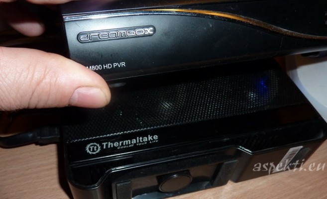
So cooling is relevant on the receiver. And here is a very interesting way of cooling with an external disc.
| Video (click to play). |
And under the Dreambox, two fans are spinning that cool the HDD and at the same time perfectly cools the receiver.

