In detail: do-it-yourself repair of an extension cord with a switch from a real master for the site my.housecope.com.
First you need to determine what the malfunction is, in the plug, in the cable or in the socket with sockets.
Most often, in extension cords, the core in the cord breaks. In order to find the fracture site and repair the extension cord, we need any consumer that can be seen when it is turned on, when not. It can be a table lamp, a radio, or the same charger for a mobile, if it has a power indicator (most often a red LED).
We include the consumer in the carrier, and begin to bend the wire in different directions every five centimeters, starting from the plug. If the problem is in the wire, then in some place where you bend the wire, the consumer will turn on, for example, a lamp in a table lamp will light up. This means that it is in this place that the wire is broken.
In order to solve this problem, you need to turn off the extension cord from the outlet, take a knife or scissors and cut a piece of wire at the fracture site, for reliability, retreat 10 cm in each direction. Now we connect the wires back. If you have a soldering iron, great, we solder the wires, if not, then you need to twist them tightly. Now we take electrical tape, and insulate each core separately, then we twist them all together.
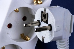
If the wire is broken in the plug of the extension cord itself, you need to unscrew the plug, cut off 10 cm of the wire, and screw it back on. If the plug is not collapsible, then you need to purchase a new one and screw it in place of the old one.
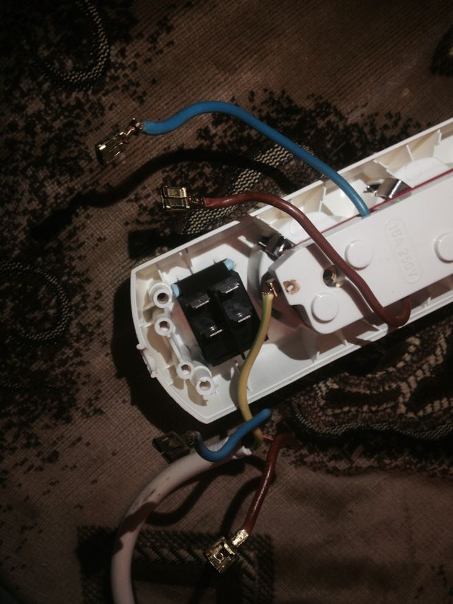
But if the wire is intact, then we check the extension block. To do this, we disassemble it, and we look at the presence of contact between the wire and the copper plates, if the wire is well and securely screwed, then there is no contact between the plug (consumer) and the plates themselves.
| Video (click to play). |
To clean all the contacts, you need to take a file and remove the plaque from the metal. If the plaque is green, it means that moisture has got into the carrier, if it is black or gray, then there was poor contact of the plug (consumer) with the plates. For good contact, we clean everything to a copper shine, and bend the copper plates to each other, the plug should fit tightly into the block.
If the copper plates have through holes in the places where the plug contacts the plates, it is also better to replace such a block.
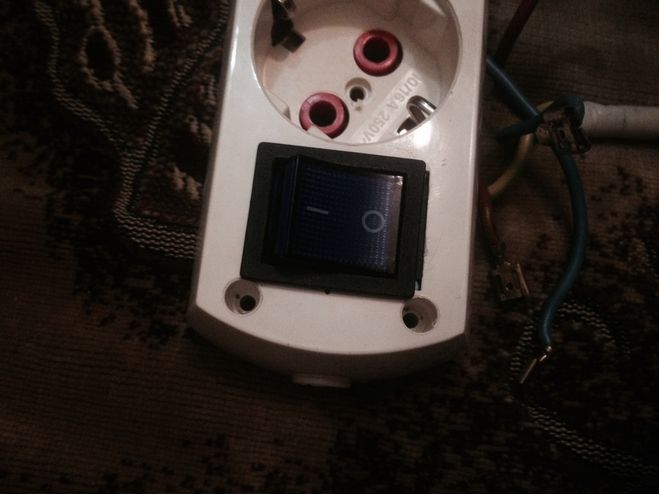
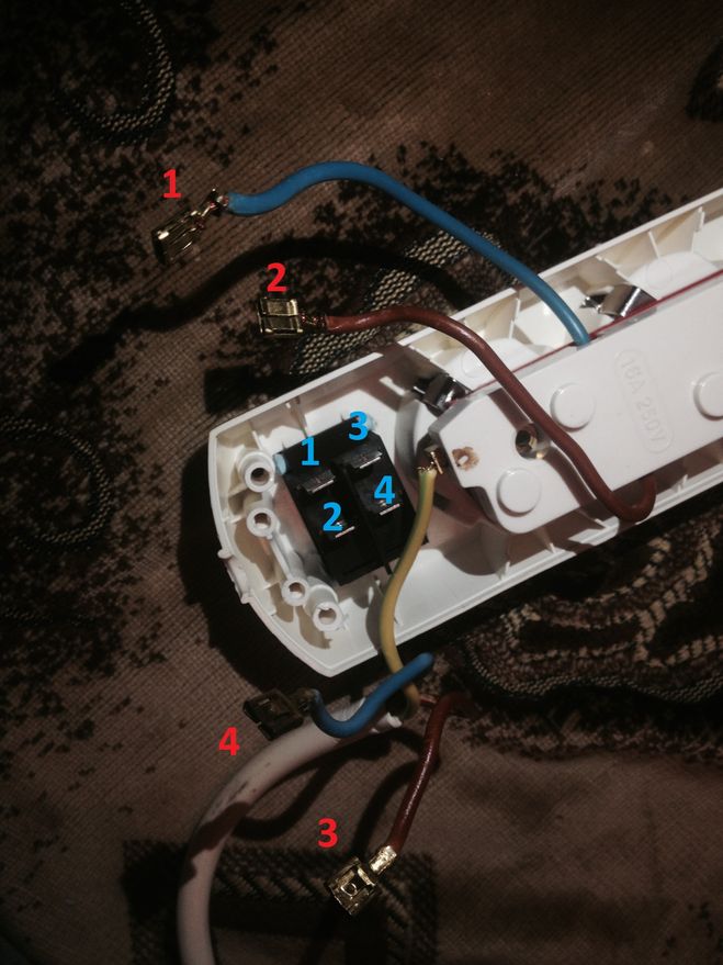
Connect the terminals (on the wires) 3 and 4 to the contacts (on the button) 1 and 3 or 2 and 4 (no difference to which, the on and off position will simply change). Connect terminals 1 and 2 to the two remaining free terminals. The button closes and disconnects the upper contacts with the lower ones. That is, in the on position, contact 1 closes with contact 2 and, accordingly, contact 3 with contact 4.
The easiest way is to buy an inexpensive tester and ring the contacts. Then it will become quite clear which outputs of the switch are closed when the button is pressed. Indeed, in the event of an error, a short circuit will occur and knock out the counter, so it is better not to risk it.
Instead of a tester, you can use a battery and some foil with a little wit. Indeed, with a short circuit, the foil will begin to heat up (I know this from experiments from childhood). Or, if you have a battery, wire, a small speaker or a light bulb, then in general you can build a good homemade continuity tester.
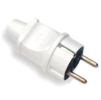
- Dismountable electrical plug.You can cut it off from a failed electrical appliance, or you can buy a new one. The requirement for the plug is that it must be grounded.
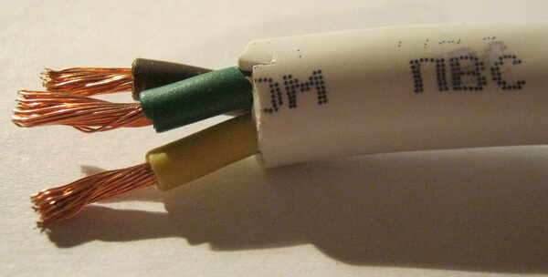
- Three-core cable of the required length. Here you need to pay attention to the purpose of the future homemade product. If powerful electrical appliances are to be connected (for example, a welding machine), the diameter of the cores must be suitable. It is better to calculate in advance the cable cross-section for current and power, so that in the future you will not face such problems as melting of the outlet and short circuit. Most often, when assembling an extension cord at home, a PVA 3 * 1.5 wire and a PVA 3 * 2.5 wire are used.
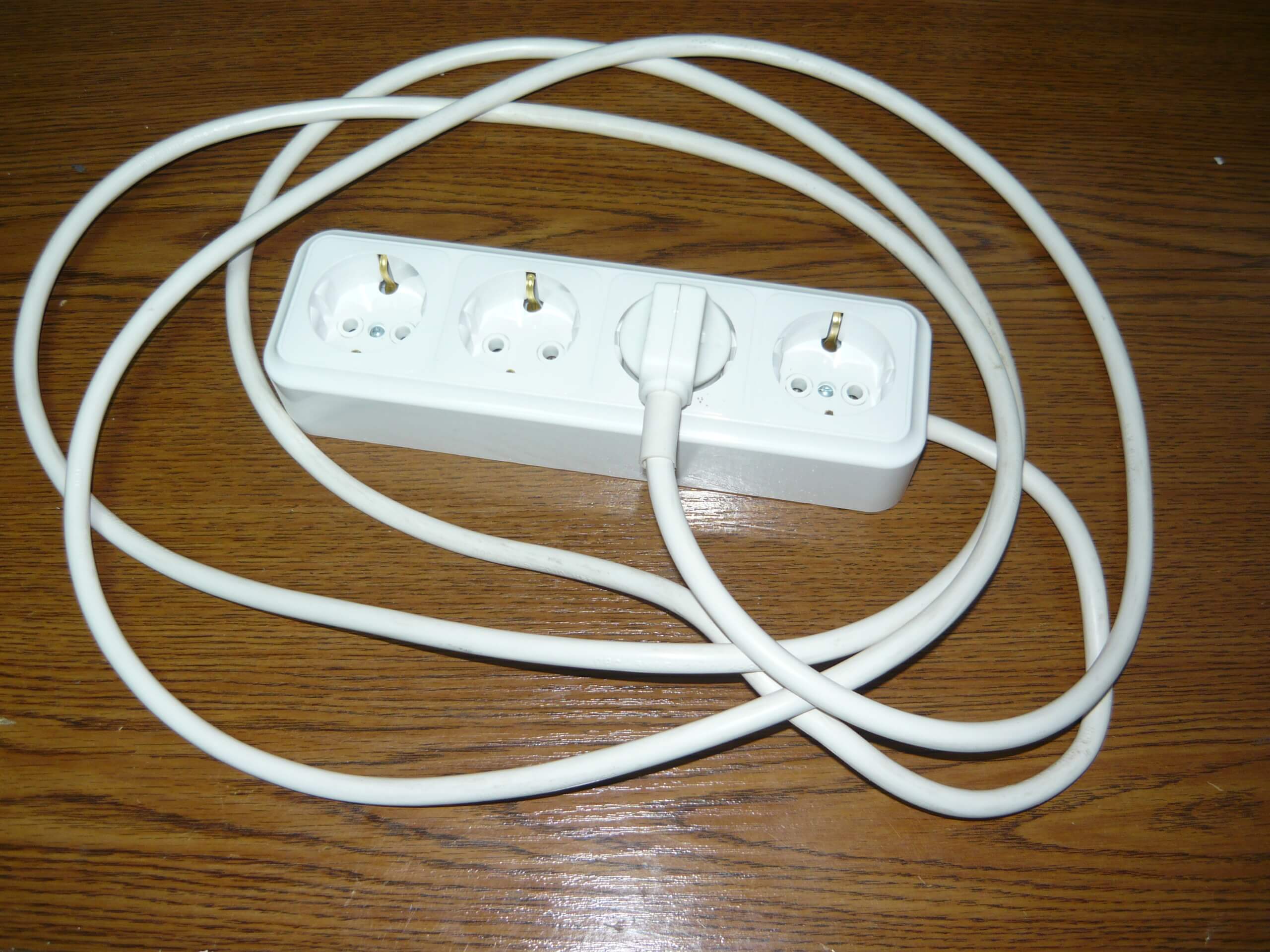
- Socket strip (or one single). There are also several main requirements: the back wall of the outlet must be closed, the product must have grounding contacts, the structure must be made dust and moisture resistant. If all these requirements are met, the issue of the safety of using such an electric carrier will not worry you in the future.
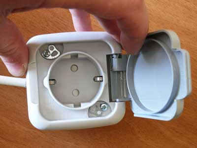
In terms of tools, you may need the following:
- a multimeter (will allow you to check the extension cord after assembly);
- curly and straight screwdriver;
- pliers or a special tool for stripping insulation from wires;
- sharp knife;
- insulating tape.
For example, consider how to make an electrical extension cord yourself from a three-core cable with 4-socket sockets. So, the assembly instructions are as follows:
- We unscrew the plug and the block of outlets to prepare the places for fixing the wires.
- We remove the upper cable sheath on both sides by 4-6 cm.
- We strip each wire 10 mm, as shown in the photo below.
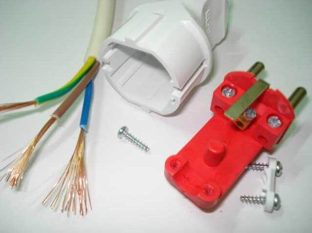
- We insert the wires into the corresponding terminals and tighten the screws well with a screwdriver.
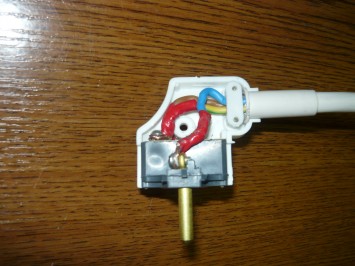

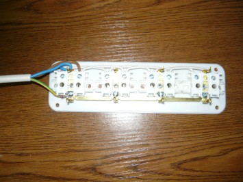


That's all the instructions for creating. We hope that now you know how to make an electrical extension cord with your own hands at home. If suddenly you have any questions, ask our specialists in the category "Question for an electrician"!
I would also like to note that it is possible to make a more reliable version of the power extension with a switch in the form of a button. In this case, you can turn off or turn on the power to the jacks. If you decide to assemble a long carrier (for example, 50 meters), then it is better to wind it on a special coil so that the wires do not get entangled constantly. In addition, the coil is more convenient to store than a bundle of wires.
We also recommend watching a visual video lesson:
A surge protector is a useful device that protects sensitive electrical appliances from power surges and impulse noise. Externally, the household filter resembles a regular extension cord, but it is additionally equipped with a built-in unit that absorbs all frequency vibrations.
To protect against large surges, the device is equipped with a fuse, which, in the event of critical overloads, instantly disconnects electrical appliances from the network.
Like any other device, surge protectors can break during intensive use.
One of the most common reasons for the failure of the mains filter is the breakdown of the on-off button, or rather the burning of the contacts inside this button.
At first, when turned on, it begins to spark, warm up and make extraneous sounds, and over time it stops working altogether. With frequent use of the filter, the button may wear out physically or get mechanical damage.
Attention! If the button of the mains filter begins to spark, heat up and / or crackle, further operation of the device is unsafe! Disconnect the filter from the mains immediately to avoid fire! For safe operation of the filter, you need to check the condition of the switch contacts and, if necessary, clean them from carbon deposits.
Let's consider the scheme of the button of a typical surge protector:
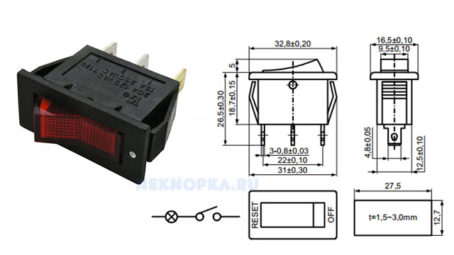
As you can see from this diagram, there is nothing complicated about the device. power filter activation buttons no, so you can repair it or replace it with a new one with your own hands.
If, when the power filter button is turned on, extraneous sounds begin to be heard, which are accompanied by the smell of melting plastic, the device should be immediately disconnected from the power. Next, you need to disassemble the power filter and check the condition of the contacts on the switch.
To do this, you need the following tools:
- soldering iron,
- crosshead screwdriver,
- tester,
- sandpaper-zero.
If the contacts are burnt out, the tester readings will confirm this (in this case, there will be no voltage at the output from the button in the "On" position). To clean the contacts, the switch needs:
- Disassemble the mains filter housing by unscrewing the mounting screws;
- Desolder the button and remove it from the filter housing. The button is held in the body by plastic clips, which should be gently squeezed out.
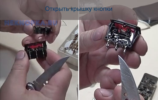
- Disassemble. To do this, you need to disconnect the key by picking it up with a flat screwdriver.
- Take out contacts and clean from black carbon deposits.
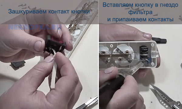
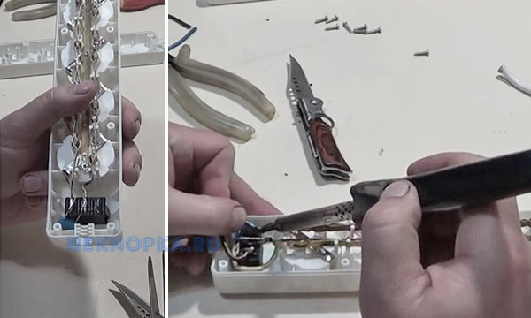
- Collect button. After that, we assemble the button in the reverse order, put it in place and solder it.
If the contacts are burned out very badly and the plastic of the switch body has melted, it should be completely replaced.
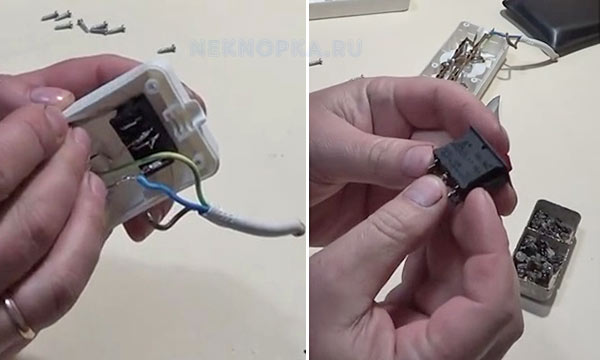
- Disassemble the filter;
- Unsolder the button;
- Remove the switch from the case;
- Install a new one in its place (sold in radio parts stores, it costs about 30 rubles);
- Solder the button, assemble the filter housing.
Often the button on the surge protector does not work due to mechanical damage. The most common case is the breakage of the latches that hold the switch key in the housing. In this case, it is not necessary to buy a new button - the clips can be restored.
To do this, you will need the following materials and tools:
- screwdriver (or drill) and drill with a diameter of 3.5 mm;
- toothpick;
- cotton swab;
- side cutters.
- A through hole is drilled in the key, into which a cotton swab is inserted (it will act as a latch).
- A toothpick is inserted inside the cotton swab for greater rigidity. On both sides, the improvised retainer is trimmed with side cutters so that it protrudes approximately 3-4 mm on each side.
- Now it remains to insert the key into the body - for this it is enough to slightly bend the sides of the seat with a screwdriver.
VIDEO INSTRUCTION
If the old button is completely out of order, and the new one is not at hand, you can connect the surge protector directly, turning it into a regular extension cord.
To do this, you need to do the following:
- Open the mains voltage filter housing by unscrewing the mounting screws with a screwdriver;
- Unsolder the wires from the button and solder them in color, bypassing the button;
- Insulate the junction with insulating tape or using heat shrinkage;
- Assemble the extension cord, test its performance.
To avoid the problems with the surge protector described in this article, when choosing a device, consider the maximum allowable power of the connected load and the maximum load current.
VIDEO REVIEW
If the total power of the equipment exceeds the maximum allowable filter power, then you should opt for a more powerful model.
There are no differences in the appearance of a conventional switch without illumination and a switch with illumination, except for the window for the illumination. The backlight works only when the lighting is off, and does not consume much electricity. The backlit switch circuit is assembled with a neon resistor and an LED resistor.

When the switch is off, the voltage is supplied to the indication through the filament of the lamp, which has a low resistance. The indicator lights up because almost 220 V is applied to it. If the switch is turned on, the indicator lamp is short-circuited by the contacts, the current goes directly to the incandescent lamp, the backlight does not light up.
A question may arise.Why is the backlight on and the lamp not on? The current through the backlight, be it a neon lamp or an LED, is limited by a large resistance, so it is not enough to light an incandescent lamp. An incandescent lamp needs a lot of current.
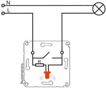
Connecting the backlight to the switch contacts
The backlit switch connection diagram can be assembled on a neon lamp or an LED with a resistor. Backlit switches assembled on an LED may not always work well with fluorescent and LED lamps. the glow of the indicator can be so small that it can be overlooked.
This is due to the fact that the resistance of the power supply of energy-saving and LED lamps is greater than the filaments of incandescent lamps. The current is limited by this resistance, and the voltage on the indicator is not enough to illuminate the switch.
Below is a simple circuit of a backlit switch, assembled on a single LED and can be easily repeated.
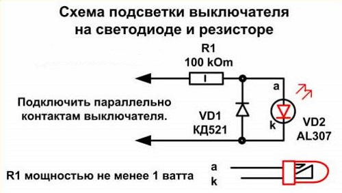
The first connection diagram of the LED backlight to the switch
The purpose of the VD1 diode according to the scheme is to protect against breakdown of the LED by reverse voltage. The reverse voltage of the LED is 20 V, and the reverse voltage in the network for it is equal to the value of the negative part of the sinusoid, which is significantly higher than the Urev of the LED. This LED backlit switch circuit consumes up to 1 kW of electricity per month, which is quite a lot.
If you want to assemble this or another lighting scheme, the connections must be twisted and soldered. Bare wires, resistors, must be well insulated with electrical tape or heat shrink tubing. Another backlight circuit on a resistor and capacitor.
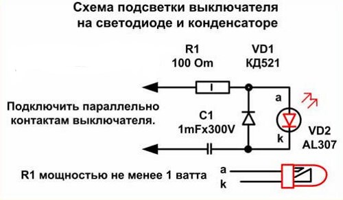
The second diagram of connecting LED backlight to the switch
The capacitor acts as a voltage divider here. The resistor in this circuit is set to 100 - 500 ohms, it is designed to limit the capacitance charge current. Electricity consumption in this backlighting scheme is less than 50W per month. The disadvantages of LED circuits include their size, however, there is enough space in the switch case.
The backlight on a neon lamp is small in size and consumes little electricity. It requires very little current to light a neon light bulb, so it is suitable for energy saving lamps and for illuminating LED light switches.
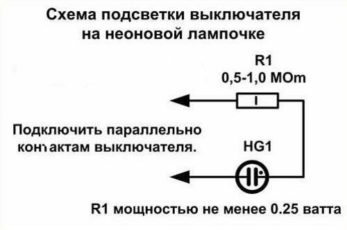
Neon lighting circuit suitable for energy saving and LED lamps
The resistor is selected with a power over 0.25 W. A neon light bulb is not difficult to find in your home. They are installed as voltage indicators in extension cords, electric kettles, irons and other household electrical appliances. Such indicators are already completely ready for installation in switches.
How to choose sockets and switches
Connecting an rj 45 socket. How to connect an internet socket
Socket in the bathroom. Requirements for sockets in the bathroom
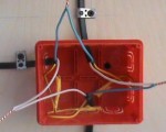
Connecting a one-button switch
11/11/2014 4 comments 21,396 views
Most often, the desire to make an electrical extension cord with your own hands arises when there is an urgent need (for example, during repairs) or when you are disappointed in finished products from manufacturers. And in truth, it is not uncommon for the outlet to melt and turn yellow when connected to a washing machine or other electrical appliance. This is due to the fact that manufacturers save on cable cross-section and assembly quality, which entails the inability to withstand the load of the network. To prevent this from happening, you can make a powerful electrical extension yourself, spending literally half an hour and a little money. Further, the readers of "Sam Electrica" will be provided with simple instructions and useful advice from our specialists!

- Dismountable electrical plug. You can cut it off from a failed electrical appliance, or you can buy a new one.The requirement for the plug is that it must be grounded.

- Three-core cable of the required length. Here you need to pay attention to the purpose of the future homemade product. If powerful electrical appliances are to be connected (for example, a welding machine), the diameter of the cores must be suitable. It is better to calculate in advance the cable cross-section for current and power. so that in the future you do not face such problems as socket melting and short circuiting. Most often, when assembling an extension cord at home, a PVA 3 * 1.5 wire and a PVA 3 * 2.5 wire are used.

- Socket strip (or one single). There are also several main requirements: the back wall of the outlet must be closed, the product must have grounding contacts, the structure must be made dust and moisture resistant. If all these requirements are met, the issue of the safety of using such an electric carrier will not worry you in the future.

In terms of tools, you may need the following:
- a multimeter (will allow you to check the extension cord after assembly);
- curly and straight screwdriver;
- pliers or a special tool for stripping insulation from wires;
- sharp knife;
- insulating tape.
For example, consider how to make an electrical extension cord yourself from a three-core cable with 4-socket sockets. So, the assembly instructions are as follows:
- We unscrew the plug and the block of outlets to prepare the places for fixing the wires.
- We remove the upper cable sheath on both sides by 4-6 cm.
- We strip each wire 10 mm, as shown in the photo below.

- We insert the wires into the corresponding terminals and tighten the screws well with a screwdriver.


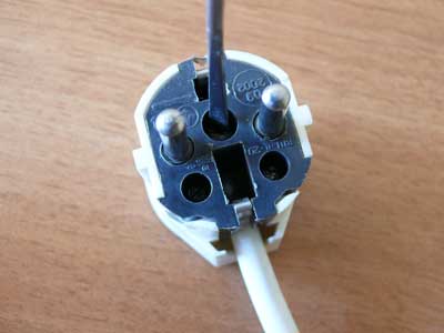

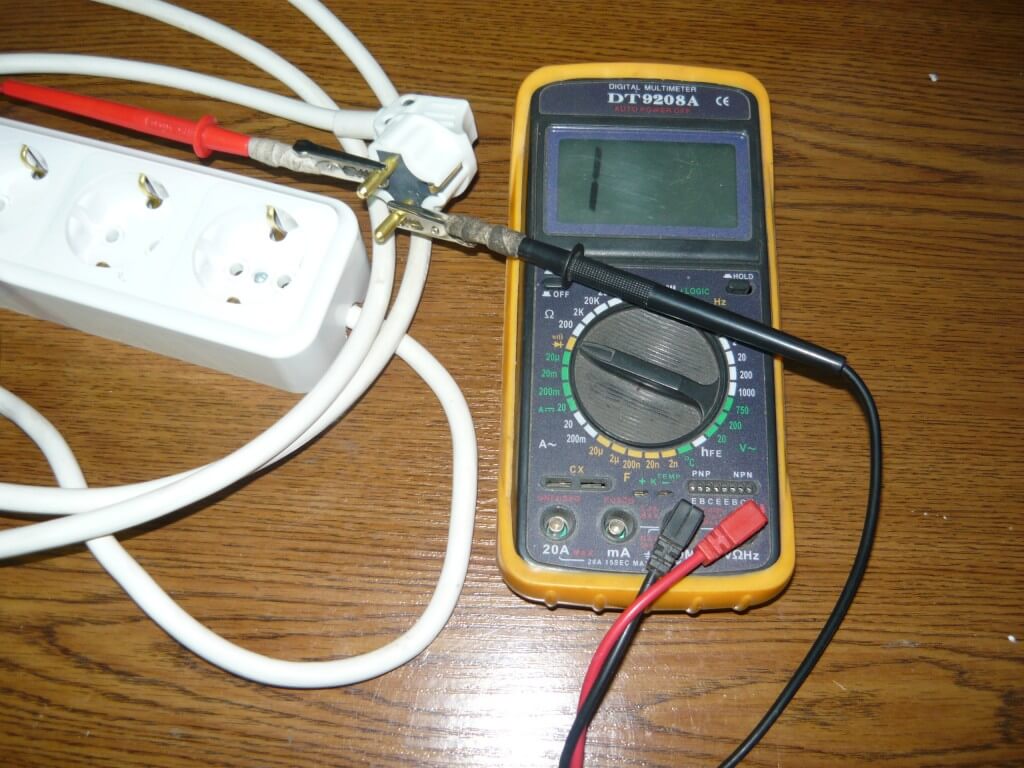

That's all the instructions for creating. We hope that now you know how to make an electrical extension cord with your own hands at home. If suddenly you have any questions, ask our specialists in the category "Question for an electrician"!
I would also like to note that it is possible to make a more reliable version of the power extension with a switch in the form of a button. In this case, you can turn off or turn on the power to the jacks. If you decide to assemble a long carrier (for example, 50 meters), then it is better to wind it on a special coil so that the wires do not get entangled constantly. In addition, the coil is more convenient to store than a bundle of wires.
We also recommend watching a visual video lesson:
Video instructions for assembling a homemade extension cord
Video instructions for assembling a homemade extension cord
If you suddenly have an ordinary household electrical extension cord out of order, you should not rush to throw it in the trash. It is easy to repair it yourself, without having a lot of knowledge in the field of electrical engineering.
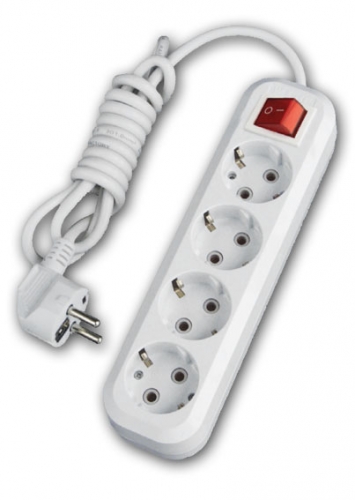
The first thing to do is to determine where the breakdown occurred, in the plug, in the cable, or maybe in the socket with sockets.
Very often, in electrical extension cords, the core in the cord (flexible wire) breaks (breaks). In order to find the place where the wire is broken and fix the breakdown, you will need to connect any household appliance to the outlet through this extension cord. The main thing is that you can see or hear well whether it works or not. Such a device can be a table lamp, a radio receiver, a charger for a mobile phone, etc. Next, we do this: we turn on the extension cord with the connected electrical appliance into the outlet and begin to bend the wire in different directions, approximately every 3-4 centimeters, starting from the plug or the extension cord itself. If the problem is a broken core, then you connect the breakage by bending the wire - your electrical appliance will turn on, for example, the red indicator light in the phone charger will turn on.This means that it was in this place that the vein was fractured.
In this option, if the wire breaks, you will need to pull out the extension cord from the outlet, take a knife or scissors and cut out a section of the wire at the fracture site, for reliability, retreat 5-10 cm to each side. After that, we strip the wires from insulation and connect them. It is advisable, of course, to connect the wires with a soldering iron, but a good twist will do. More details about connecting wires can be found in this article - "Connecting wires". You need to insulate the connection with an insulating tape, first insulating each core separately, and then the entire wire as a whole.
If the cause of the breakdown is in the electrical plug, then it must be unscrewed, if the contact is oxidized, then we clean it, and if the wire breaks, then we cut off 10 cm of the wire from the plug, clean it and screw it back on. If the plug is not collapsible, then you need to purchase a new one and screw it in place of the old one.
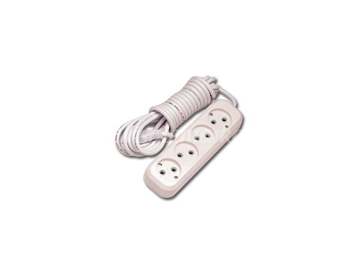
If the cause of the failure is not in the wire or in the plug, then we check the extension block. To do this, we disassemble it, and we look at the presence of contact between the wire and the copper plates, if the wire is well and securely screwed, then there is no contact between the plug (consumer) and the plates themselves. In order to clean all the contacts, you need to take a file and remove the plaque from the metal. If the plaque is green, it means that moisture has got into the carrier, if it is black or gray, then there was poor contact of the plug (consumer) with the plates. For good contact, we clean everything to a copper shine, and bend the copper plates to each other, the plug should fit tightly into the block. If the brass strips have through holes where the plug contacts the strips, it is best to replace the brace.
That's the whole repair of the electrical extension cord!
See several ways to repair an extension cord yourself.
Hello everyone! An article from the series - DIY electronics repair. In this article, you will learn five ways to repair an extension cord (carrier) with your own hands.
To repair an extension cord, we do not need any parts, only tools.
If you have a broken extension cord, and you do not know how to repair it, or how to find a breakdown to fix it, then this article is especially for you.
To repair an extension cord with your own hands, you will need the following tools:
Breakage of extension cord No. 1
Very often, the first line to the extension cords breaks the wire, that is, it refracts partially or in half. Sometimes there is an open fracture as shown in the photo.
In such cases, you need to act carefully and naturally. It is necessary to take one wire, for example, blue and connect it to the same blue, the same operation must be performed with another wire.
After that, first wrap one wire with insulating tape, and then the other. At the end, wrap the entire affected area very tightly. If you do everything right, the extension cord will serve for more than one year.
Breakage of extension cord No. 2
Most often, closed refraction of the wire is formed in the extension cord. In such cases, it seems that nothing can be done, but I assure you that there is always a way out.
In this case, you need to start by looking for a breakdown, namely to find which conductor broke off. A special device, a voltmeter, or a multimeter, will help us with this. It is necessary to set the indicator to resistance, and attach one contact to the plug, and the other to the wire.
If resistance is shown on the dial, this means that two contacts have shorted through the conductor and the carrying wire is working, and if it was not shown, then the wire is broken.
So, after finding a breakdown, it can also be repaired, as in the first case.
Breakage of extension cord No. 3
I think the breakage that is easiest to fix is the plug breakage. To repair an extension cord, you just need to cut off about five centimeters from the plug and replace it with a new one.
The cut wire must also be carefully stripped and attached to the pins of the plug. You will need to purchase not a disposable plug, as shown in the photo, but a plug that contains the bolts.
I must warn you that there is a very high voltage in the outlet, so the wire to the plug must fit very tightly, since in case of accidental contact or short circuit, a short circuit or electric shock may occur.
The least common breakdown occurs in the box with outlets, but it is easier to fix.
For example, a wire broke off from the main bulkhead. In this case, you need to heat the soldering iron and simply solder this wire. I also want to give advice to all this, you need to take a large piece of tin and rosin, moisten the partition and wire with rosin, and only then solder.
A large piece of tin is needed for good soldering, so that this conductor holds well and does not have to be repaired over and over again. That's roughly, as you see in the photo.
If suddenly not one conductor breaks off, but two at once, then you need to cut off 2 - 3 centimeters of the wire, strip somewhere 1 centimeter and turn the same operation.
And here is the last most difficult breakdown of all. This melting occurs only when closed. It is difficult to fix it, because the wire is completely melted.
The only thing you can do with your own hands is to replace it. You can take a similar wire from another conductor, where, for example, a box has broken, or any device with a long wire.
But be careful! 220 volts will pass through this wire, so the wire is needed no thinner than the one that was before.
Or in this one case, you can buy a new extension cord, as many people do.
How to replace the on / off button on the extension cord?
Everyone writes correctly. you need to connect the contact to the terminals. Usually someone who is familiar with an electrician never throws in anything. The savings are terrible. I cut off the burnt-out part and inserted a new one.
I envy me so much money is wasted, I throw it away, but you can fix it!
The easiest way is to buy an inexpensive tester and ring the contacts. Then it will become quite clear which outputs of the switch are closed when the button is pressed. Indeed, in the event of an error, a short circuit will occur and knock out the counter, so it's better not to risk it.
Instead of a tester, you can use a battery and some foil with a little wit. Indeed, with a short circuit, the foil will begin to heat up (I know this from experiments from childhood). Or, if you have a battery, wire, a small speaker or a light bulb, then in general you can build a good homemade continuity tester.
P.S. It is a pity that you did not write what the result of the inclusion was.
As the authors have already written, it is necessary to reconnect the terminals to the contacts, only it is more convenient to buy a new extension cord, their price is not higher than one hundred rubles, I saw quot; Magnetquot ;, they are of different lengths, you can choose the one you want.
You have already been told how to connect the wires. If you are in doubt about the correct connection of the wires, make yourself a simple probe.
Supply power to the extension cord, not 220 volts, but some kind of quot; harmlessquot; voltage, for example, 1.5 volts from quot; finger quot; batteries, take a light bulb designed for the same voltage and stick the wires soldered to it, alternately into the sockets for power consumers with both switch positions.
Connect the terminals (on the wires) 3 and 4 to the contacts (on the button) 1 and 3 or 2 and 4 (no difference to which, the on and off position will simply change). Connect terminals 1 and 2 to the two remaining free terminals. The button closes and disconnects the upper contacts with the lower ones. That is, in the on position, contact 1 closes with contact 2 and, accordingly, contact 3 with contact 4.
I would not change the button of the extension cord, because if it burns out, then the extension cord itself may be faulty. Our computer burned out from a faulty socket.After that, we bought special extenders with fuses, as the master advised.
On the body of the switch there is a contact diagram, according to which you need to connect your wires. Moreover, there is nothing to solder here, but it is connected by a simple connection of the terminals.
As an example, parsing a Sven extension cord. See an example and connect in the same way. Another picture to help and an article on this topic.
We have a similar extension cord, they also bought not at a cheap price. The thing is very useful in everyday life. Moreover, there are other different extension cords (not very long, we suck one long). One of them also has an on / on button, but it burned out, so my husband completely removed this function and still works fine. Maybe you will do that too, but it's up to you.
I will guide you according to your photo (the extension cord, of course, must be de-energized):
- connect the terminals with red numbers 3 and 4 (wires) to the contacts of the switch with blue numbers 1 and 3 or 2 and 4 (choose the required pair yourself)
- the remaining terminals with red numbers 1 and 2 connect to the remaining pair with blue numbers (1-3 or 2-4)
- connect the parts of the extension casing, insert the plug into the outlet and flip the switch button to verify the positive result.
It's good that there are photos. You can understand them and make connections correctly. Wires numbered three and four can be safely connected with switch contacts numbered one and three, respectively. Well, then the wires with numbers one and two need to be connected with pins two and four. Connect the extension casing, plug into the socket and flip the switch.
How to fix a faulty extension cord / surge protector with your own hands.
Published: 12 months back
The internal structure of the illuminated switch and how to connect it correctly. Watch the video and you will understand everything. How to connect an illuminated switch. How to connect a switch with illumination
Make your own homemade free energy generator - 100% work !! You will need only: lighter and extension lead. Check this out! My attempt at making an endless source of energy using a surge protector and a piezo from a lighter.
When choosing a connection cord, it is necessary to take into account the diameter (cross-section) of its wire. This value must be large enough to support the anticipated load.
Long cords and cables themselves have a natural resistance to electricity. For this reason, the voltage at the points of connection to the source and the device can differ significantly, and this, in turn, is quite noticeably reflected in the operation of the electrical device itself.
In other words, the longer the cable length and the current required for the operation of the tool, the larger the wire diameter is needed.
Recommended wire diameters depending on their length and current strength.
Extension cords often fail. Due to rough handling, there is a high likelihood of damage to this cord. For your own safety, try to regularly check such lamp and extension cords for any signs of damage.
Classic extension cord for European plug.
In order to provide sufficient flexibility for the cord, the wire in it is usually stranded. When connecting it, it is necessary to twist the wires of the wire so that they fit snugly together. Under no circumstances should you replace electrical wiring with extension cords, as they are for temporary use.
If you find any damage to the insulation of the cord, be it cracks or dry out, it must immediately be replaced with a new one. Even though the cord can be “patched up” with insulating tape, don't risk it and fork out for a new one.
Believe me, replacing an old damaged cord with a new one will save you more than eliminating the consequences of a possible fire.After all, cords from lamps and other low-power devices can cause a fire in the house or, even worse, electric shock. Fortunately, today the cost of such cords is low. Extension cords that are used for outdoor work and are exposed to moisture must be completely insulated.
White extension cord from a Chinese manufacturer.
An extension cord with grounding has three wires. It must be checked for an open circuit. The green wire is the grounding wire and must be connected to the round grounding prong from the plug. The other two pins are flat, so it is difficult to confuse them. Here is such a simple device for plugs of no alternative connection.
A non-alternative three-prong plug: phase, neutral, and earth. Essential elements:
- grounding pin;
- phase wire pin (black);
- neutral wire pin (white);
- screw clamp for the cord.
The two-wire cord is used with lamps and low-power extension cords. One of the two wires in a cord is usually insulated with a longitudinal groove. In such a simple way, the zero (white) wire is marked. It connects to the tinned (white) screw of the socket or plug contact. Accordingly, the second wire of such a cord is phase (black) and is connected to the brass screw of the plug or socket.
A low-power extension cord with a notch on the "neutral" wire.
Even if it seems to you that it is very easy to assemble an extension cord yourself, this video will very clearly demonstrate all the necessary stages of work.
If you notice damage to your plug, or if the pins in it are not properly secured, it must be replaced immediately. For for normal and safe operation of the device, there should be no signs of damage on it, and the bare wires are securely hidden in the plug itself. Cut off the cord before replacing the old plug. Since the section of the cord close to the plug is most often subjected to all kinds of bends, it should be cut off and discarded.
Repair of any plug begins with untwisting its body.
It is recommended to cut at a distance of 51 mm from the fork. Next, clamp the plug and remove it from the case. In this case, on the other hand, hold the body itself, and not the cord. Otherwise, you run the risk of spoiling the plug contacts, or simply tearing the wire.
There are a huge number of different models of surebets. There are plugs with contacts that pierce the insulation of the case, and there are also plugs with screw or screw contacts. In order to remove unnecessary mechanical stress on the wires, sometimes they are fixed in the housing with a clamp. In addition, there are plugs with a third grounding cord. Unlike a flat phase and zero, it has a round shape.
Insulation-piercing plugs are typically used with cords for low-power electrical appliances such as radios, lamps, watches, etc. There are many different models of this kind of forks.
Installation of a typical plug with insulation piercing pins. Installation steps:
- Squeeze the pins and slide them out of the housing.
- Cut the end of the wire and insert it into the plug body.
- Open the pins and insert the wire into the hole on the back of the pin block.
- Squeeze the pins and insert them into the body. In doing so, the needles located at the rear ends will pierce the insulation and provide contact with the wire group under the insulation.
There are also plug models that have screw terminals. These plugs are primarily used with two-wire cords for low to medium power appliances. But there are also plugs for three-wire grounded cords.
Some of them are equipped with a special clip in the case, which securely fixes the wires so that they do not break when you pull the plug from the socket by the wire.
When installing a plug with screw contacts, it is necessary to pass the cord through its body and separate its wires by about 2.5 cm.The ends of the wires must be stripped by 12.5 mm. Then tie the wires with a safety knot as shown in the diagram below.
A fall arrest knot is ideal for tying wires in a plug.
Such a knot makes it impossible to disconnect the wires from the contacts when the plug is pulled out of the socket. The bare wires of each wire must be twisted into a strand and wrapped clockwise around the screw. Tighten the screws and you're done!
A disc made of plastic or fiberglass is put on the pins and, thereby, covers the ends of the wires that are in the plug body. In this case, the wires inside are tied into a safety knot.
Plug with screw terminals for low and medium power devices. Elements:
- screw contact;
- pin;
- safety knot;
- the wire is wrapped around the screw only clockwise.
Remove the plastic or fiberglass insert that protects the fork body.
Pass the cord through the body and strip the ends 12.5 mm, after which the wires must be tied in a knot. This unit removes the mechanical stress from the contacts.
Thread the pre-stripped end of the wire clockwise around the screw. In this case, the neutral wire must be connected to a wide pin, if one exists. It remains to return the plastic insert to its place.
There are plugs with prongs of different widths, which can only be connected to an outlet with the appropriate receptacles. Due to the fact that this plug has only one option for connecting to the outlet, it will not allow you to connect it incorrectly, making the neutral wire of the device a phase. The phase (black) wire in such a plug is connected to a narrow pin, and the zero (white) wire to a wide one.
Also today there is a wide variety of socket couplings. They fit in exactly the same way as plugs and look like a socket fitted at the end of the extension cord.
Typical plug at the end of an extension cord. Essential elements:
- extension cord;
- clip for wire;
- upper part of the case;
- brass screw;
- screw contact;
- green screw;
- mounting screws;
- the lower part of the case;
- white screw;
- it is advisable to screw the bare end of the wire onto the screw exclusively clockwise.
As a rule, low-power switches have insulation piercing contacts. Such switches are usually used to control lighting lamps. For more powerful electrical consumers, there are switches with screw contacts. The installation process for both types of switch is practically the same. The main thing is to always follow the instructions that come with the device.
Before starting work on the installation of the switch, make sure that the power cord is de-energized. Cut a small piece of the phase conductor and tuck the conductor into the back of the breaker body. Close it with the front and secure with the fixing screws.
Do not forget to first check the instructions, whether all the wires are laid in their places. While tightening the screws, the wire insulation is pierced with special metal needles that come into direct contact with the wire under this insulation. It is this circumstance that makes it possible for the mechanism located behind the switch wheel to close and open the circuit.
The main stages of installing the switch on the wire.
First of all, cut a small piece of the smooth phase wire.
Open the switch and arrange the wires as instructed. To put the wheel in the on position. and off, it must be rotated counterclockwise. This wheel is directly connected to the mechanism, which ensures the closing and opening of the phase conductor contacts.
On the front of the case there are both a wheel and a mechanism for opening and closing contacts.When mounting on the back of the case and then tightening the fastening screws, the needles pierce the insulation, due to which the contact of the wheel with the phase wire works. The retaining screw must be tightened properly to secure the two halves of the case together.
There are many reasons for your lighting fixture to malfunction. If the lamp blinks or is completely inoperative, you should first check the lamp itself. Remove it and insert it into the holder of a known working lamp.
If it does not light up in the working device either, replace it with a new one. If the new light bulb does not show signs of life, try connecting the lamp to a different circuit, which probably has voltage. If this does not bring any result, the malfunction may lie in the plug, cord or lamp holder.
Unplug the device from the wall socket and open the socket. Check the cartridge, and at the same time the plug for defects in the contacts. They must be tightly clamped.
What the lamp holder consists of.
The main elements of the lamp holder:
- thread;
- outer casing;
- an insulating cover that fits over the chuck.
V Some lampholders use a rotary knob instead of a pushbutton switch. Elements:
- metal base;
- brass screw;
- zero and phase wires;
- safety knot;
- cap;
- threaded connection with lamp.
In addition, you should check the cord for an open circuit. If no break is found, check the cartridge. To do this, remove it from the lamp and check with a tester. Check the zero loop first. To do this, connect the alligator clip to the metal part of the socket, which has a thread, and touch the tinned (white) zero contact screw with the tester plug. The tester's light should come on.
Checking the zero circuit of the lamp holder for an open circuit. It should be checked from the zero side of the chuck.
In order to check the chuck switch, clamp the brass screw with a crocodile and touch the center of the chuck with the plug. The tester's light should be on when the switch is on.
Try flipping the switch to the on and off positions. If it does not respond, then the switch needs to be replaced. Do not even try to repair the cartridge itself. Better buy a new one.
Checking the switch with a tester. Elements:
- open circuit tester;
- contact for the base of the bulb in the center of the socket;
- brass screw.
Before removing the socket from the lamp, unplug the device from the outlet. There is a spot on the chuck housing marked “press to compress”. Clamp the shroud at this point and remove it from the chuck. Next, unscrew the contact screws and remove the cartridge itself.
Installing a new lamp holder. Elements:
To install a new socket, remove the socket cover from the lamp. It is usually secured with a threaded connection. Slide a wire through the tube of the lamp and leave an end long enough to tie the safety knots and connect a new socket.
Then connect the phase wire to the brass contact and the neutral wire to the white one. After you understand the connections, slide the insulating and outer shrouds onto the chuck. Slide on the outer casing by squeezing it with your fingers. If you hear a click, be aware that the serrated edges clicked, which means that the chuck cap is connected to the casing.
If it seems to you that a lamp holder is a trivial thing, do not jump to conclusions. Some of the models below will definitely surprise you.
E27 bulb holder with remote control.
E27 lamp base with integrated switch. Power 1200 W, maximum current 6A.
E27 lamp holder with tee. Three lamps instead of one in one socket is the ideal solution in a number of applications.
Adapter for 4 studio lamps E27 up to 250W.
| Video (click to play). |
As you can see, even something as simple as a lamp holder can be very interesting and unusual.

