In detail: do-it-yourself 4g usb modem repair from a real master for the site my.housecope.com.
For a person who does not sit still and cannot do without the Internet on his laptop, a CDMA modem is a necessary device in the user's arsenal. Usually, such modems have a USB interface, which is very convenient for use, but during operation, due to negligence, it is usually the USB plug that breaks down and it becomes necessary to repair the modem.
Repairing such a malfunction requires some "creative" approach to insert the plug back into the modem, see an example of such a repair in the pictures below. If the damage is not severe, then you can align and leave the original plug, but it is better to put a new one, which is certainly more reliable.
The article is out of date. We no longer repair 3G USB modems.
The second common problem is wear and tear on the moving parts of USB modems. Usually, the wires or ribbon that connects the plug to the device board are frayed. An example of such a malfunction and how to fix it can be seen in the pictures below.
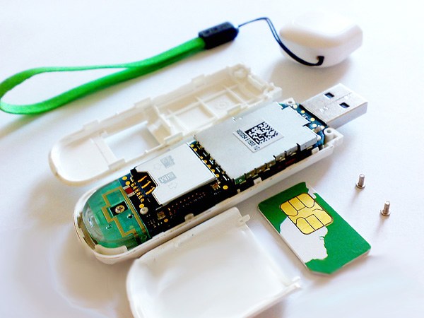
Another type of malfunction is damage to the SIM card receiver when contacts or the entire SIM slot are broken. In this case, it is necessary to replace the sim-receiver, choosing the appropriate size and contact group.
The modem loses connection or gives out a weak network signal if the input circuits and the modem antenna are faulty, in which case it may be necessary to replace the signal amplification chip or repair the device antenna.
Unlocking the modem from the operator is necessary if you want to use the purchased modem with a sim-card of another telecom operator, which for one reason or another is more convenient for you.
| Video (click to play). |
Never a Russian person, given the opportunity to save money, will not refuse this. If the Internet speed is low in the country or outside the city, in an apartment or a cottage, why buy additional devices? We will tell you how to make the simplest and cheapest external antenna for a 4g lte modem with your own hands.
Antennas are devices for signal amplification. They are of different types:
- narrowly focused;
- sector;
- omnidirectional.
The simplest are omnidirectional. They can receive and transmit a signal in all directions with the same intensity. An example is a conventional quarter-wave vibrator. To put it simply, this is an ordinary piece of wire that has a quarter-wavelength of the received signal.
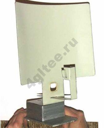
Sector is capable of limiting radiation in a specific sector. For example, if you put a sheet of iron behind the omnidirectional antenna, you get a sector antenna with a sector of 180 *. Such a sheet of iron is called a screen.
The most effective is a directional antenna, which is a special case of a sector antenna. Due to the selection (of course, an accurate calculation in fact) of the curvature of the screen, you can get a narrowly directed beam of radio wave radiation.
The two main characteristics of any transceiver are sensitivity and gain. The sensitivity affects the quality of the received signal, the gain factor - the transmitted one. These parameters are measured in dBi. Sensitivity is measured in negative numbers, gain is positive. The more modules of these numbers - the better, the better your device is. For example, sensitivity at -75dBi is worse than -83dBi. 11dBi gain is better than 6dBi. The higher these parameters, the greater the range of the established communication.
A typical collecting focusing external amplifier for a modem is sold in the store and costs money.
If you have a case from an old PC (and they are usually spared to be thrown away and taken to the dacha - suddenly come in handy), then you can make an external directional 4g antenna with your own hands.You will need the whole body, the scissors for the hardware, and you will have to buy a USB cable for your external amplifier.
We will not describe the steps, they can be seen from the drawing.
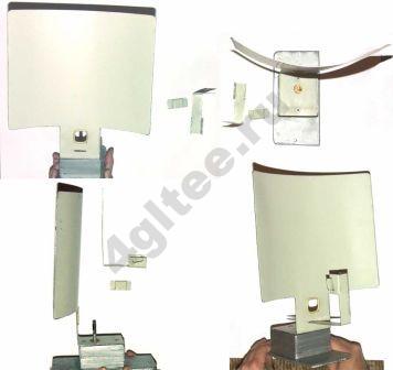
You can simplify the design.
If there is no piece of metal, take thick cardboard and cover it with foil.
If you are too lazy to paste over, look in the kitchen among the dishes. You can make just such an antenna for a 4g modem with your own hands.
Thanks to user Ukshuinik, who was not too lazy to upload all the drawings.
To make an external homemade antenna for a 4g lte modem with your own hands, you will need:
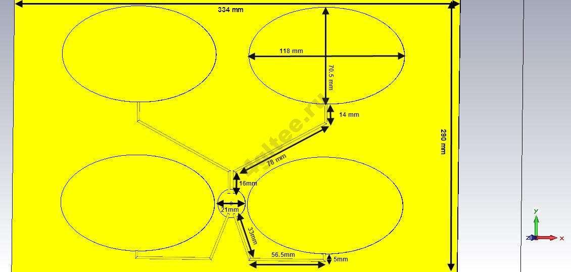
- Galvanized iron sheet for 334mm * 290mm panel and for four patches, each of which is 118mm * 70.5mm.
- A coil of copper wire with a diameter of 2 mm.
- A piece of copper foil for cutting a nickle 4a with a diameter of 21 mm.
- Styrofoam under patches.
- Adhesive for gluing patches to foam.
All dimensions of the external device are shown in the drawing.
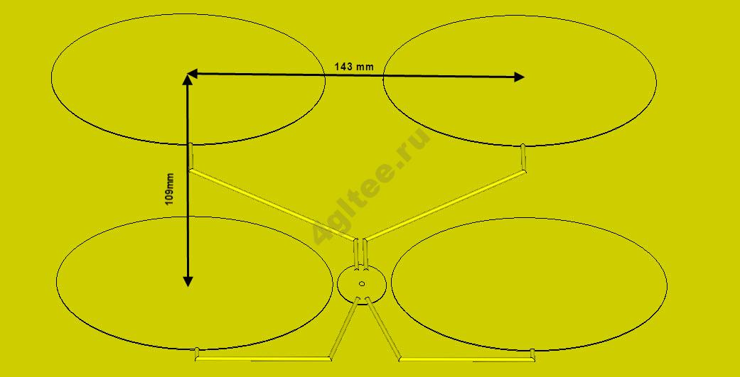
Make a full-size drawing of the external amplifier on paper, lay out the patches. Then bend the wire and solder it to the patches. Drill a hole for the cable plug in the base and solder the plug. Then cut the circles out of the foam, glue them to the base where the patches are. Glue the structure on top.
To use such an external antenna to amplify a 3g / 4g signal with your own hands, the modem must have a cable connector.
The device is named after the engineer who first came up with it. This powerful external antenna for a 4g usb modem is made by hand, the diagram of the desired option can be found on the Internet. We will present the simplest one.
All parameters are calculated depending on the transmission and reception frequency of the modem. The calculator can be found here.
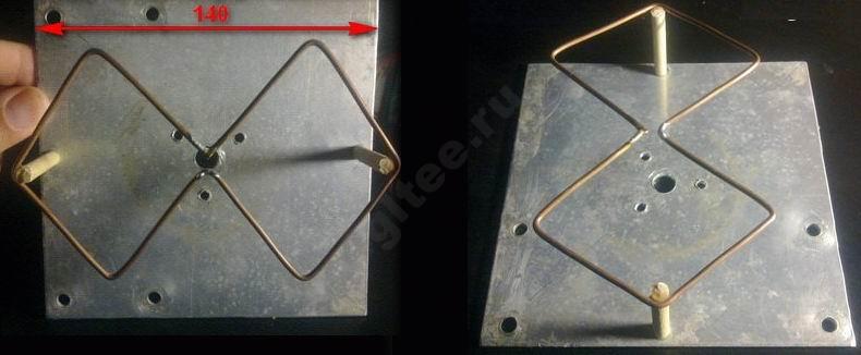
You will need copper wire, a sheet of aluminum with a thickness of 2 mm. First, you need to bend the wire so that the sides do not touch in the middle. And solder the ends.
A hole for the cable is drilled in the center of the plate.
Then a wire is attached to the platinum. It should not touch the reflector.
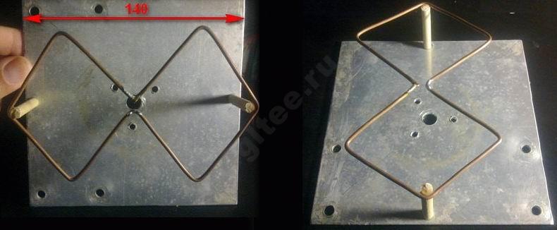
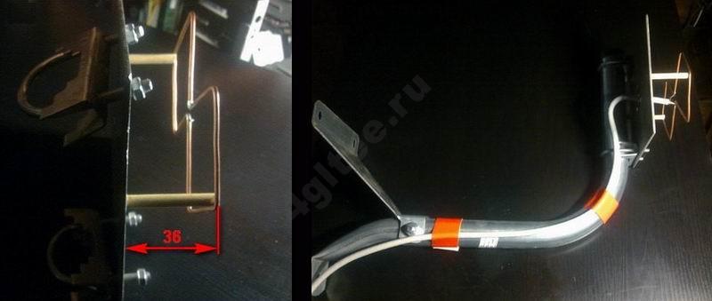
Further, it is attached to the satellite dish bracket or simply to a stick.
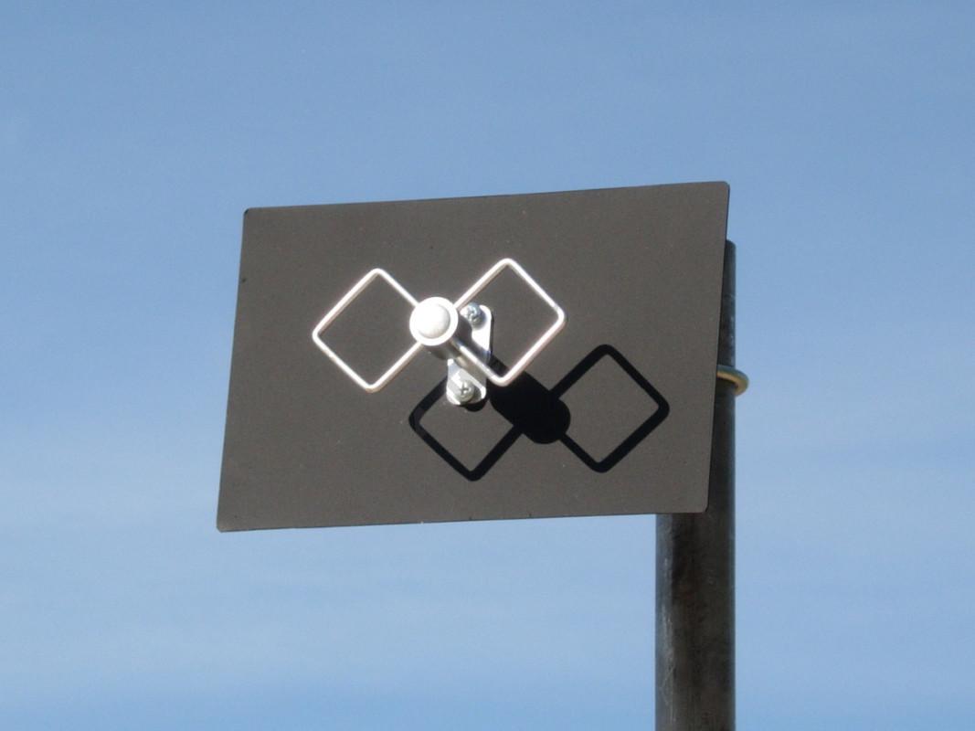
If the modem has a connector for an amplifier, then all that remains is to connect. If not, then you also need to prepare it yourself. Need copper foil for PCBs. Wrap the modem 2/3. Solder the cable. Make a second layer. And secure.
Today, many citizens use wireless Internet, but at the same time strive to increase the speed of its work. After all, excellent access is guaranteed when the modem is close to the base station of the mobile operator. In this regard, those who work in the Internet far from the station are content with low speed. Is there a technical way to solve this problem? The best option is a 4G antenna with your own hands.
The so-called Kharchenko antenna, which is designed for a 3G modem, is a homemade model. There is nothing particularly complicated in its arrangement. The zigzag design was proposed by the scientist K. Kharchenko back in the 1960s. Today it is quite popular among radio amateurs not only for its simple design, but also for its excellent repeatability and broadband. The latter advantage applies especially well to the spiral design.
By their own design, the models can be quite different. Based on the size of the plate, the frequency of the structure changes significantly. At the same time, it must be borne in mind that homemade antennas can include objects made of plastic and metal.
There are different types of antenna for the modem. The simplest is omnidirectional. It can receive and transmit a signal in all directions equally intensively. In particular, this can be a simple quarter-wave vibrator. In simple terms, this is a piece of wire that has a quarter-wavelength of the signal that is being received.
A sectoral antenna can limit radiation in a specific sector. In particular, if you put an iron sheet behind the omnidirectional device, you get a sector structure. Its sector will be 180 degrees.Such a sheet of iron is called a screen.
The most effective is the directional design. Thanks to the correct choice of screen curvature, you can make a narrow beam that will emit a radio wave.
The main antenna nodes are:
- a vibrator, on which the induction occurs, the guidance of a wave of electromagnetic oscillations, which are sent by the transmitter of the cellular operator;
- a cable with a matching unit that transmits the induced signal directly from the vibrator;
- signal transmission node from the cable directly to the modem input;
- reflector that removes interference as well as reflected signals to increase the receive power.
Kharchenko's antenna with his own hands is an excellent device for everyone who wants to have high-quality communication without having to spend large funds. It is very easy to make it even for an ordinary person who does not have the appropriate professional skills. The result is excellent indeed. This design will last for a long time.
As a rule, an external antenna with your own hands for a 4g modem is endowed with two square components. The performed calculation of the Kharchenko antenna for a frequency of 2100 MHz shows that the dimensions of the sides of the component should be 53 millimeters each.
At the same time, to reduce the internal resistance of the antenna, craftsmen advise making not square components, but diamond-shaped ones, in which the angle is 120 degrees.
Detailed instructions are set out in this video:
In order to increase the effective use of the antenna for the USB modem, it is equipped with a reflector - a steel plate. It can be made of foil-coated PCB. The distance between the antenna and the reflector should be 36 millimeters. In order to create a distance between the antenna and the reflector, you can use some kind of cap or box.
The 4g signal amplifier for the modem has certain device features. Any steel plate can work in the form of a screen. Such a screen can be cut with scissors directly from tin or from an outdated aluminum pan using a grinder, or even made of a piece of plywood or cardboard material and pasted over using foil. There won't be much difference. If only he blocked the obstacles that are coming. Experts advise using some kind of DVD disc for the antenna. Its one side is wrapped in aluminum foil and copes well with wave reflection. In addition, it looks beautiful and contributes to a significant simplification of work. You just need to spread it with glue and fix the plastic bottle caps at the end, adjust the distance of the vibrator from the amplifier by adding additional washers or cutting off excess thickening.
Experts advise making a Kharchenko antenna from a wire made of copper. Its cross-section should be 5 mm. sq. or be with a diameter of 2.5 millimeters. It should be noted right away that you can take a thickening of 2.3 millimeters (the cross-section is 4 mm sq), which will not significantly reduce the reception parameters. It is also permissible to carry out an installation with a cross section of 2.5 mm sq, but this will lead to a deterioration of the signal, increasing its attenuation. However, for a certain area this is quite acceptable.
The high frequency cable must be soldered to the antenna. But here a problem in the form of a braid may appear. Many cheap cables cannot be soldered using rosin. You can solve this problem if you use a simple F-connector, screwing it over the cable. A piece of copper wire should be soldered to it, and the entire structure directly to the antenna.
Users often have a question, which cable should be used to get a 4G panel antenna? The main difference that you can face is the size of the characteristic impedance, which can be fifty or seventy-five ohms. To reduce power loss, it is better to use a cable with a lower resistance.It is better suited for electrical performance, better guarantees the lowest signal loss. But using one of these types of cable, it is better to more accurately make the mechanical dimensions of the vibrator for it. In this case, the signal power loss will be the smallest.
The resulting structure must be securely fixed using hot melt glue. After that, it remains to connect the antenna to the modem and tune to the maximum signal level. If the modem is not equipped with a connector for an external antenna, then you should simply make three to four turns of the main conductor around the USB modem.
THIS REPAIR SHOULD BE CARRIED OUT ONLY BY PROPERTIES WITH THE PROPER QUALIFICATION AND TOOL! ANY ATTEMPTS OF UNQUALIFIED INTERVENTION THREATS A LOSS OF WARRANTY, REMOVAL FROM THE EQUIPMENT, DAMAGE TO THE MAIN BOARD AND OTHER NON-POSSIBILITIES! Likewise, the AUTHOR DOES NOT BE RESPONSIBLE FOR UNQUALIFIED REPAIRS OR ANY OTHER INTERVENTION! THIS ARTICLE IS NOT A GUIDE TO REPAIR EQUIPMENT AND ONLY SHOWS THE QUALIFICATION OF A SEPARATE MASTER!
Not so long ago we bought a 4g modem from Altel because one of our engineers needed such a thing for domestic use.
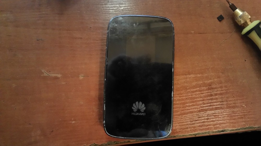
We bought it not working at first, it did not turn on then after the charging procedure with a normal cable, it nevertheless turned on.
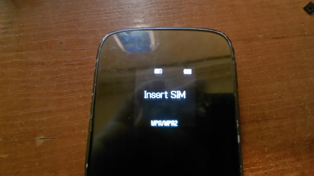
The modem said that you need a SIM card. We put a SIM card but the modem did not see it either. I decided to look inside the device.
We move aside the back cover of the device.
ATTENTION BEFORE BEGINNING TO REMOVE THE COVER, YOU MUST REMOVE THE BOLT FROM THE SIDE ON THE CASE UNDER THE CAP WITHOUT THIS YOU WILL RUN OUT THE COVER.
I did not have this bolt because I am sure that I am not the first to disassemble it.
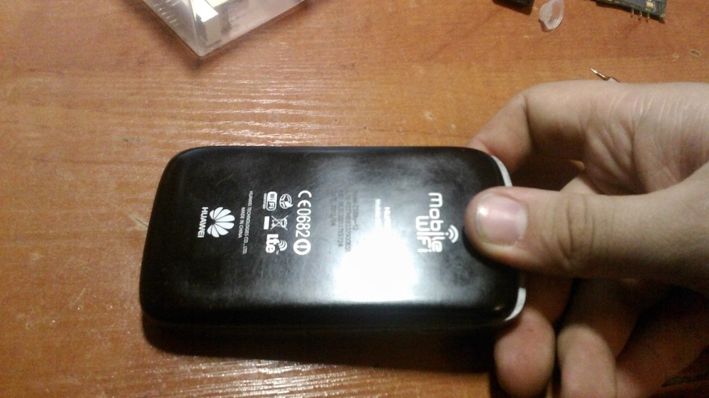
I removed the cover and the battery and the housing bolts appeared before us.
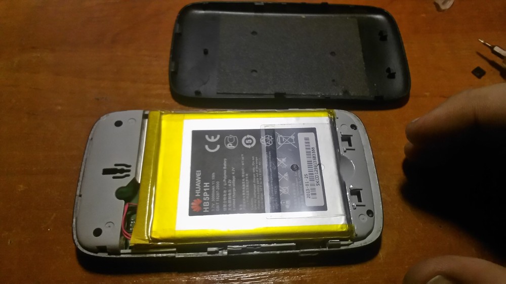
Gently pulling out the battery, it is firmly glued to the double-sided tape.
to the side of the case, therefore, do not overdo it and not break the case or battery.
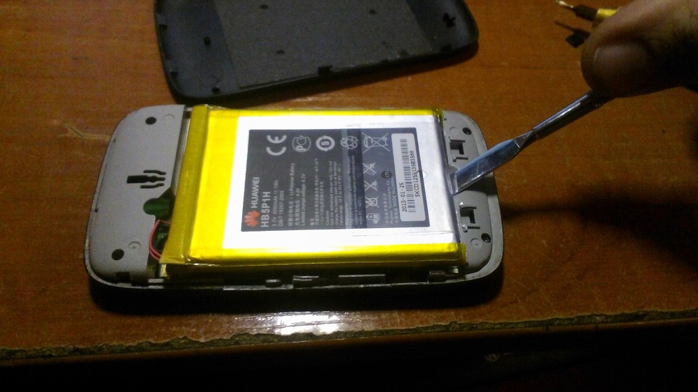
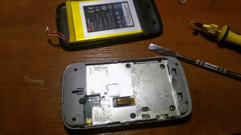
After this procedure, as elsewhere, the bolts are unscrewed.
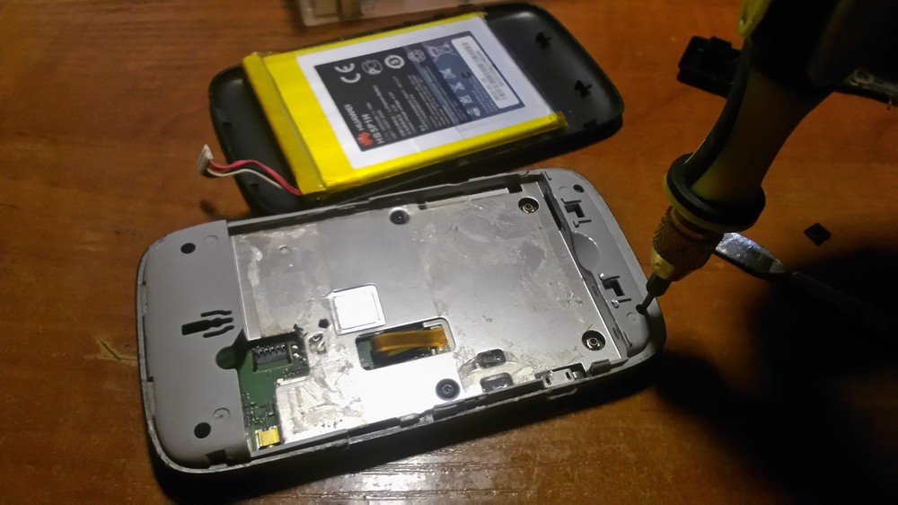
I take everything out of the case (in this case, everything just spills out on the table since the modem is in a terrible state)
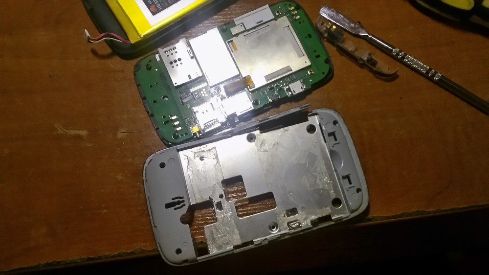
Initial examination showed a suspicious absence of contacts on the SIM card slot.
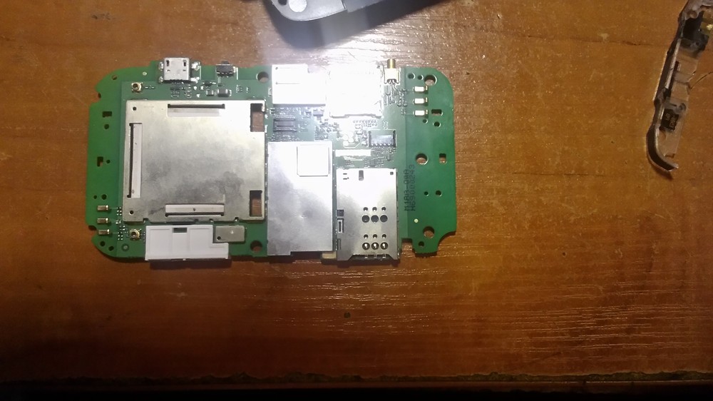
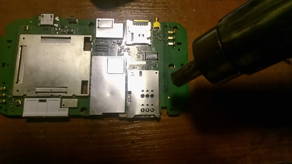
He warmed it up with a hairdryer and after a few seconds the lid gave in.
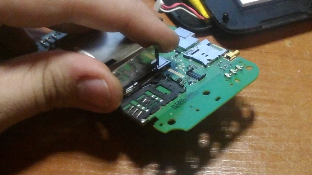
I open the lid and we see 2 bent and one missing contacts.
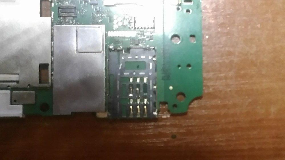
That is why he did not read the SIM card. We did not have such a connector in the service.
therefore it was postponed until better times when we find such a connector.
THIS REPAIR SHOULD BE CARRIED OUT ONLY BY PROPERTIES WITH THE PROPER QUALIFICATION AND TOOL! ANY ATTEMPTS OF UNQUALIFIED INTERVENTION THREATS A LOSS OF WARRANTY, REMOVAL FROM THE EQUIPMENT, DAMAGE TO THE MAIN BOARD AND OTHER NON-POSSIBILITIES! Likewise, the AUTHOR DOES NOT BE RESPONSIBLE FOR UNQUALIFIED REPAIRS OR ANY OTHER INTERVENTION! THIS ARTICLE IS NOT A GUIDE TO REPAIR EQUIPMENT AND ONLY SHOWS THE QUALIFICATION OF A SEPARATE MASTER!
DrShadow Service Center Device Master was with you 8 771 4062266;
Subscribe, wait for the second part, there will be many more interesting things.
At the moment when I wrote comments on the articles of the Mozhochin, I literally lost the Internet in mid-sentence. First of all, I went to look at the modem, where I found out that it was finished - not a single LED was on. After thinking a little, it was decided that there was nothing to lose (the guarantee was over long ago), and the autopsy no longer scares me.
This article is more of a success than a natural victory over a breakdown, but still. I am a person a little distant from delicate electronics, but I can distinguish a burnt look. Therefore, having disassembled this device
the following picture was presented to the light white:
After careful sniffing and inspection, the gaze settled on this condenser.

Its shape changed markedly, although there was no gap. The marking informs that its capacity is 3300μF and voltage is 16V. Since I don't have an LC meter, I continued examining it with a multimeter and measuring its resistance. So it interested me.The charge was taken very reluctantly, and the increase in resistance quickly stopped.
After that, two Soviet capacitors, with a total capacity of almost half of the original, were pulled out of some frames.
After connecting one capacitor in parallel, the power LED showed signs of life, which meant the correct course of my thoughts. Having soldered the second one, I tried to turn on the modem - and, lo and behold, the Internet started working! Therefore, I can write this article! 🙂
Now it remains to spend $ 0.5 to buy the original capacitor, and 10 minutes of time to assemble everything in a bunch! Of course, this is not a detailed analysis of the modem repair, but still a description of one of its breakdowns. So if someone comes in handy - I'll be glad! :)
After purchasing a powerful soldering iron, I decided to continue the repair. Armed with a new unit, I still managed to pull out this evil condenser.
In its place, a capacitor found at work, although inferior in capacity, was hoisted.
After that, the modem blinked merrily with LEDs.

And he briskly sent a bunch of information packets through the wires. :)
- We fill the niche part 3 or make a chest of drawers out of garbage with our own hands - 12/20/2014
- Filling a niche part 2 or making corner shelves with our own hands from garbage - 12/19/2014
- Filling a niche part 1 or making shelves with our own hands from garbage - 12/19/2014
- The idea of decorating a repaired wire with your own hands - 09/30/2014
- DIY plywood box - 09/22/2014
- Do-it-yourself drawing on T-shirts - 09/15/2014
- Do-it-yourself sealed container for welding electrodes - 09/02/2014
- DIY assembly on dowels or thorns - 07/27/2014
- Cabinet and shelves as an idea for filling a niche - 07/25/2014
- Do-it-yourself folding table-cabinet - 07/15/2014
- Making a universal playing board with our own hands - 07/05/2014
- We clean jeans from spilled PF-115 paint with our own hands - 07/01/2014
- Do-it-yourself Eurobook sofa cover - 01/07/2014
- Convenient case for a multimeter with your own hands - 12/26/2013
- DIY winter mask - 12/20/2013
It is important to add that when installing the Conder it does not overheat it, and also does not confuse the polarity (if you confuse it, when you turn it on, there will be "pshshshshsh" and swelling of the freshly soldered Conder).
Absolutely fair! Pay attention to the color coding. In general, I try to take pictures first. Well, and the popovod of overheating, you also need to be careful.
why is the quality of photos so bad
Because they were done in poor lighting. And everything is clear to such pictures, so I see no reason for indignation.
And also due to the fact that the camera was not at hand, and the only thing that was at hand was a phone 🙂 and that Samsun, bought for work.
Dried or swollen electrolytes sometimes drag other parts on the boards with them. So replacing capacitors doesn't always help.
Comrades! Thank you for your help! Based on your advice, I still managed to bring my modem to a human form, and finish writing an article!
This is a solder with a high content of lead, if you do not have a powerful soldering iron at hand, then I use a turbo lighter
Usually - take a more powerful soldering iron.
I got a new soldering iron today. Let's see what happens!
Guys! Guard! I can’t evaporate this ill-fated capacitor! Help with advice! I warm him - but he is not in any! I already coated it with solder so that the heat transfer was better, and still does not want to! What do you do?
Sorry for my "correctness", I just want to earn M $ 🙂
Everything is fine! We must strive for excellence! :)
And also in the sentence "After which two Soviet capacitors were pulled out of some frames, with a TOTAL capacity of almost half of the original" there is an error in the word SUMMARY.
In the sentence "After the PARALLEL connection of one capacitor, the power LED applied to the PICTURES of life" there are errors in the words PARALLEL and SIGNS!
good day, 70% of all computer breakdowns (motherboards, power supplies and video cards) that I encountered were just such a breakdown, drying out or swelling of an electrolytic capacitor, it happens that the kander did not swell and there is a sticky puddle on the board where it is soldered or the appearance of a fat spot is also a factor in the failure of the latter, and I rarely use the LC_meter, basically I check them in the same way as the author, I solder them and alternately change the polarity of the instrument probes with a multimeter,
Cool) Mozgochin will not be left without an Internet or even electricity. There is always a way)
P.S. 70% is a lot. You can open a workshop knowing this
Your browser doesn’t support canvas.
Is your TV, radio, mobile phone or kettle broken? And you want to create a new topic about this in this forum?
First of all, think about this: imagine that your father / son / brother has an appendicitis pain and you know from the symptoms that it is just appendicitis, but there is no experience of cutting it out, as well as the tool. And you turn on your computer, access the Internet on a medical site with the question: "Help to cut out appendicitis." Do you understand the absurdity of the whole situation? Even if they answer you, it is worth considering factors such as the patient's diabetes, allergies to anesthesia and other medical nuances. I think no one does this in real life and will risk trusting the life of their loved ones with advice from the Internet.
The same is in the repair of radio equipment, although of course these are all the material benefits of modern civilization and in case of unsuccessful repairs, you can always buy a new LCD TV, cell phone, iPAD or computer. And for the repair of such equipment, at least it is necessary to have the appropriate measuring (oscilloscope, multimeter, generator, etc.) and soldering equipment (hair dryer, SMD-hot tweezers, etc.), a schematic diagram, not to mention the necessary knowledge and repair experience.
Let's consider a situation if you are a beginner / advanced radio amateur soldering all sorts of electronic gizmos and having some of the necessary tools. You create an appropriate thread on the repair forum with a short description of “patient symptoms”, ie. for example “Samsung LE40R81B TV does not turn on”. So what? Yes, there can be a lot of reasons for not switching on - from malfunctions in the power system, problems with the processor or flashing firmware in the EEPROM memory.
More advanced users can find the blackened element on the board and attach a photo to the post. However, keep in mind that you are replacing this radio element with the same one - it is not yet a fact that your equipment will work. As a rule, something caused the combustion of this element and it could “pull” a couple of other elements along with it, not to mention the fact that it is quite difficult for a non-professional to find a burned-out m / s. Plus, in modern equipment, SMD radioelements are almost everywhere used; The subsequent restoration of which will be very, very problematic.
The purpose of this post is not any PR of repair shops, but I want to convey to you that sometimes self-repair can be more expensive than taking it to a professional workshop. Although, of course, this is your money and what is better or more risky is up to you.
If you nevertheless decide that you are able to repair the radio equipment on your own, then when creating a post, be sure to indicate the full name of the device, modification, year of manufacture, country of origin and other detailed information. If there is a diagram, then attach it to the post or give a link to the source. Write down how long the symptoms have been manifesting, whether there were surges in the supply voltage network, whether there was a repair before that, what was done, what was checked, voltage measurements, oscillograms, etc. From a photo of a motherboard, as a rule, there is little sense, from a photo of a motherboard taken on a mobile phone there is no sense at all. Telepaths live in other forums.
Before creating a post, be sure to use the search on the forum and on the Internet. Read the relevant topics in the subsections, perhaps your problem is typical and has already been discussed. Be sure to read the article Repair strategy
The format of your post should be as follows:
Topics with the title “Help fix the Sony TV” with the content “broken” and a couple of blurred photos of the unscrewed back cover, taken with the 7th iPhone, at night, with a resolution of 8000x6000 pixels are immediately deleted. The more information you post about the breakdown, the more chances you will get a competent answer.Understand that the forum is a system of gratuitous mutual assistance for solving problems and if you are dismissive of writing your post and do not follow the above tips, then the answers to it will be appropriate, if anyone wants to answer at all. Also keep in mind that no one should answer instantly or during, say, a day, no need to write after 2 hours “That no one can help”, etc. In this case, the topic will be deleted immediately.
You should make every effort to find a breakdown on your own before you get stumped and decide to go to the forum. If you outline the entire process of finding a breakdown in your topic, then the chance of getting help from a highly qualified specialist will be very great.
If you decide to take your broken equipment to the nearest workshop, but do not know where, then perhaps our online cartographic service will help you: workshops on the map (on the left, press all buttons except “Workshops”). You can leave and view user reviews for workshops.
For repairmen and workshops: you can add your services to the map. Find your object on the map from the satellite and click on it with the left mouse button. In the field “Object type:” do not forget to change to “Equipment repair”. Adding is absolutely free! All objects are checked and moderated. A discussion of the service is here.


Typically, in the elementary school curriculum, children are taught to first find the root of a word. However, this approach is incorrect, as it leads to possible errors in the search for morphemes in a word. The sequence of actions should be as follows:
1. Determine the part of speech to which the word belongs. It is important to do this right away. For example, if the token is immutable, there will be no ending. Also, do not be lazy to remember the features of the formation of this type of tokens.
2. Next, find the ending. To do this, you need to select the maximum number of options with different endings, and then graphically highlight the ending.
3. Mark the existing suffixes and postfixes, which are always preceded by the ending. Do not forget that the same parts of speech are often formed according to the same model and have the same formative suffixes, of which there can be more than two.
4. If you have followed the two previous steps correctly, then determining the stem of a word will not be difficult. Select the base graphically, highlighting all the words except the ending, since this mass is not included in the base.
5. Designate graphically the prefix (prefixes) of the lexeme. For the purpose of self-control, try to choose several variants of lexemes of the same part of speech with the same prefixes.
6. The last stage is the selection of the root of the word. Note that complex tokens can have two roots. In this case, do not forget to graphically indicate the connecting vowel.
How to repair USB Yota modem?
Manufacturers of Yota modems, and many users also argue that this USB modem cannot fail in principle - simply because there is nothing to break there. Nevertheless, practice sometimes refutes this point of view. So if the owner, for example, uses the modem in the car, then the modem can escape from any almost inattentive gesture. Result: By itself is a USB connector, and the modem is by itself. The situation is not the most pleasant, agree?
If to a lesser or greater extent in technical you understand the wisdom, then you can try to repair the Yota modem with your own hands. To describe the process in short, let's say that it consists of a disassembly modem, soldering the necessary elements and assembling all the parts in place. The USB modem should be disassembled very carefully, taking into account the location of the components of the "vital" device. To get to the loop, we slightly press on the modem cover from the back side (where the Yota icon is) and move it towards the USB connector. A plastic plate is fixed on the latches under the lid, which must also be removed. Next, we need to unscrew the pressure plate that secures the USB connector housing. We remove the board and the printed circuit board from the case with the details of the modem.Disconnect the USB cable from the board. We take out the case of the USB connector, turn the modem itself perpendicularly and carefully squeeze the USB case out of the modem. Next comes the case for disassembling the USB connector, which must be carefully opened along the seam.
In the process of soldering, you need to solder the wiring from the USB case to the corresponding places on the modem board. It is better to do this with a small soldering iron and using a magnifying glass. We check this way: install the ribbon cable into the modem board, and the connector into the computer's USB port.
Before assembling, it is imperative to fix the USB connector in the case: this can be done with glue (the option is not the most effective), but it is better to unbend a paper clip, make a hole with a soldering iron in one of the halves of the USB connector and install a paper clip instead of the factory rod. Then you can put back the modem and the case.
True, with the absence of the appropriate devices, and even more so, the dexterity and abilities, it is better not to tackle the repair of an independent USB modem. You can always contact a service center at least inexpensive, where they will do everything for you as it should be. Otherwise, you risk "killing" your modem completely, and without the possibility of returning it under warranty or exchanging it.
You can ask questions only after registration. Login or register, please.
Greetings to members of the forum. I decided to publish the idea of my homemade receiving 3G antenna, ideas were collected from all over the world, with their own modifications. The search for the optimal result lasted 1.5 years from the usual antenna from the "heater" to the last working version. I will make a reservation in advance, all measurements of the signal strength were measured in dB. If the signal is 0 for 3G, then it is -113 dB, and the weak measurement of the Huawei E1550 modem in 1 stick of division is 99-95 dB. At 95 dB, the download speed is sufficient for watching online videos from YouTube.
So the first version of the antenna was taken from a conventional heater, is relevant in the room, the greatest effect is directed to the window of the base station (BS), the signal increase is insignificant, by about 4-6 dB.


Another version of the antenna, the Kharchenko antenna, I will not describe a lot of descriptions on the Internet. I will say that the signal is actually amplified no more than 9 dB.

I will describe the last version of the antenna, the most effective. gain up to 30 dB.
What we need. First, go to the site
We recalculate the dimensions for 2100 MHz, more precisely 2050 MHz.

1) this is the length of the wire in a circle (one circle).
2) the distance from the rings to the reflective reflector.
In an oval, these are the height and width of the reflector.
Next, we take a soldering iron, a copper core from 1.5 - 2.5 mm, in the store we purchase a can of canned food, as an option, some other reflector, we take a 75 Ohm cable with copper braid and a central core, a copper tube, it is difficult to pass through the tube 75 Ohm cable, if you remove the insulation, then the tube easily enters the cable. We solder.
We get what is in the picture. There is already a ready-made version. I painted it a little from oxidation, oxidation reduces the signal and the efficiency of the antenna. If you need more details, I will also make an antenna at my leisure, I will take a more detailed photo.

Further.
To improve, to increase the signal, I used Supral 0.6, it can be a larger size, although Supral 1.2 and more ..., accordingly, the gain will be greater. For me, the option with Supral 0.6 came up.


Antenna presets. The antenna was tilted 26.5 degrees. the calculations are to be viewed from the antenna offset angle data. Took the data and description from here
Description
• To point the antenna parallel to the horizon, it is necessary to correctly position the dish on a vertical support. (See Figure 1)
• I have always preferred to mount the cymbal upside down. But if the rod of the feed holder does not rest against the support when setting the desired tilt of the dish, then you can set the dish in its normal position.
• In order for the antenna radiation to be directed along the horizon, set the angle to 26.5º. between the plane of the plate and the vertical. (see figure 2). The value of this angle can be taken from the antenna documentation. It is called “the angle of inclination of the focal axis of the antenna” and for reflectors sold under the SUPRAL trademark is 26.5º.
• To set the angle of inclination, you need a plumb line and a tape measure.We measure the diameter of the plate in height with a tape measure and multiply by sin 26.5º and set the resulting value horizontally between the upper edge of the plate and the vertical taken from the lower edge using a plumb line.
• FOR EXAMPLE: we have a plate with a diameter of 600 mm then the required value will be equal to sin 26.5º x 600 = 267.7.
• If you use a feed with an offset mounting center, it must be taken into account that the angle of the antenna radiation direction will also be offset by the offset angle of the center of the feed mount.

I got such an adapter. Can be found on the internet.


And I will also add links to an interesting version of the antenna Panel 3G antenna 16 dBi
There, by this link, there are more options for other antennas.
I think this option can be made from scrap materials and the gain is not bad, and not, as I said above, to buy a specially satellite dish, although I myself have bought a satellite dish for a long time and have not used it. Although the price for my antenna is about 600 rubles. + 75 ohm cable 250 rubles + homemade adapter (scientific repeater) is no more expensive than "Chinese blende", and most importantly a working version. Thank you.
| Video (click to play). |
P. s. Who needs real help to help, please contact.

