In detail: do-it-yourself antenna amplifier repair from a real master for the site my.housecope.com.
Antenna amplifier for TV is widespread in the CIS. It is the optimal solution for improving the quality of the tele-signal. The intrinsic gain in the antenna does not play a significant role, but its antenna amplifier seriously affects the picture quality.
The best amplifiers that have proven themselves over the years are SWA-7, 14, 17, 107, 109, 2000. The SWA-2000 is a newer antenna amplifier with two additional transistors. The amplifier includes two transistors VT1 and VT2, which are included in accordance with the circuit to the OE. The signal is removed at the collector in the transistor VT2 and is fed through the capacitor C9 to the cable. The location of additional transistors VT3 and VT4 is carried out in active circuits, which provide a base bias voltage in transistors VT1 and VT2.
Despite the fact that digital television is being actively introduced, there will always be demand for antennas with active amplification, since the signal to the TV tuner is supplied using antennas with a decimeter range.
So, to improve the television signal, they use an antenna amplifier. The best gain is achieved when the antenna amplifier is installed not near the TV input, but in close proximity to the antenna. To reduce attenuation, it is better to use modern coaxial cables. The amplifier is powered by a coaxial cable. The voltage rating of the power supply in the antenna amplifier is most often 12 V, and the attenuation value of the cable is 0.1 - 0.5 decibels per m, if we take different television channels.
| Video (click to play). |
In rural areas, when telecentres are at a great distance, amplifiers are used, the gain of which is more than 100 dB. If the amplifier was chosen incorrectly, or the feeder and antenna are not matched properly, then due to the excitation of the amplifier, the TV screen will show with noise and snow.
Although you can buy an antenna amplifier for your TV at almost any corner, most of them use a standard circuit. That is, they are two-stage aperiodic amplifiers having bipolar high-frequency transistors connected in accordance with the OE circuit. Let's take a closer look at these models: SWA-36 and SWA-49
The SWA-36 amplifier contains broadband amplification stages with transistors VT1 and VT2. The value of the antenna signal, through the matching transformer and the capacitor C1, is fed to the base in the transistor VT1, which is included in the circuit with the OE. The determination of the operating point in the transistor is carried out due to the bias voltage, which is determined using the resistor R1. In this case, due to the action of negative feedback (OOS), the characteristic in the first stage becomes linear, the position of the operating point is stabilized, however, the gain value decreases.
No frequency offset is applied to the first stage. The execution of the second stage is also carried out using a transistor in a circuit with an OE and with OOS, due to the passage of voltage through the resistors R2 and R3. However, there is still a current OOS, through the resistor R4, which the emitter circuit possesses. It stabilizes the transistor VT2. To avoid large gain losses, the resistor R4 is grooved using a capacitor C3, which has a relatively low capacitance (10 pF).
The result of this is that the lower frequencies in the range of capacitance on the capacitor C3 will be significant and the AC feedback leads to a decrease in the gain, due to which the same frequency response of the amplifier is corrected. The SWA-36 amplifier has drawbacks, among them the passive loss that the output circuit has.
The device of the SWA-49 amplifier can be considered the same, with the exception of some differences.
It implements the best decoupling of the power circuits, due to the filters L1C6, R5C4 and increased the gain, thanks to the capacitors C5 and C7.
In a high-quality antenna amplifier, the signal-to-noise ratio should increase. However, any electronic amplifier necessarily has its own noise, which is amplified like the signal. For this reason, the traces of important parameters in the antenna amplifier need to highlight the noise figure. If its value is large, it is pointless to increase the gain.
Broken TV antenna power supply? Do not rush to the store for a new one, this master class will allow you to repair your “native” adapter with your own hands and use the saved money for more necessary things.
Visual signs of a malfunction - the LED in the power supply case either does not light up at all, or periodically goes out.
We check the resistance of the primary winding of the mains transformer with a tester by connecting the test leads of the device to the mains plug of the power supply. The measurement result should be in the range of 2.5-2.7 kOhm.
In the absence of a circuit, a break in the wire connecting the plug and the transformer is possible, but a malfunction of the transformer is more common.
Next, we check the resistance at the contacts of the antenna plug, to which the power wire is soldered - the device should show that there is no short circuit.
Unscrew the screws securing the housing cover and remove it.
Now we unscrew the self-tapping screw for securing the board and take it out. In some models of power supplies, the board is simply inserted into special grooves and its fixation with a self-tapping screw is not provided.
Checking diodes D1-D4. The resistance of serviceable diodes in the forward direction will be 450-650 Ohm, in the opposite direction - to infinity, taking into account the process of charging the electrolytic capacitor.
In our case, all the diodes turned out to be operational.
Now it's the turn to check the health of the voltage stabilizer microcircuit.
The purpose of the microcircuit pins (see photo): left - power output (12 V), middle - common, right - input (15-20 V).
To make the verification process more visual, I soldered a yellow wire to the output, a black wire to the common one, and a red wire to the last input.
Naturally, during the repair process, we simply connect the tester probes to these points.
We check the value of the voltage supplying the microcircuit. As you can see in the picture, this parameter is within 21 V, which is normal.
Now we check the output voltage.
Here we see that the output voltage spontaneously rises to 18 V, then.
... drops sharply to almost zero. Such jumps occur two or three times a minute, but still more often the power supply does not produce anything at all.
Note that this type of failure of an integral stabilizer is rare, usually the voltage at its output is completely absent.
This is how the already soldered stabilizer microcircuit looks like.
Its marking - 78L12 - indicates that the stabilizer is designed for a voltage of 12 V. We select instead the same or similar with a stabilization voltage of 9-12 V.
It should be borne in mind that with a supply voltage of 9 V, the amplifier will reduce the gain, and increasing the voltage above 15 V can damage the amplifier.
We insert a new microcircuit and solder it.
We check the voltage at the output of the power supply unit - the tester shows 12.1 V. The repair of the power supply unit is almost complete.
We add that if the antenna has been in operation for more than two years, it is advisable to check the electrolytic capacitor 100 μF, 25 V.
In the event of a loss of capacity by this capacitor, one or two dark horizontal stripes moving in the vertical direction will be visible on the TV screen; the image at the top of such stripes can be bent to the left.
If the capacitor is defective, then it is better to change it with a new one with an operating voltage of at least 50 V.
We collect the refurbished power supply. When it is connected to the network, the control LED lights up - the device is working properly.
Being careful, we connect the antenna cable to the connectors of the plug and continue to use the power supply unit repaired by our own hands, while saving on the purchase of a new adapter.
A thunderstorm has passed and the signal from the terrestrial antenna has disappeared. What happened? Why is there no signal in non-analog range not in digital t2? - you ask. The answer is obvious. Thunderstorm! Lightning discharges carry a static voltage that knocks out active antenna amplifiers, power supplies, digital set-top boxes t2, and sometimes the televisions themselves. Therefore, during a thunderstorm, it is recommended to turn off all devices from the 220V electrical network, and disconnect the antenna cable from the TV or T2 receiver. Ideally, of course, a lightning protection, a lightning rod with a good ground loop should be installed, but even these precautionary methods do not give a 100% guarantee against lightning striking the antenna.
Lightning protection, of course, is a good thing, but what to do if lightning still got your home.
First you need to understand what went wrong. We start by turning on the TV. If the TV turns on, it's already good, but it happens that the input receiving unit flies out. Suppose you have a t2 receiver installed that receives a digital signal from a decimeter antenna and transmits it to the TV - we also plug it into the 220v network and see if it turns on. The t2 tuner turned on, let's go further (turning on the TV and the t2 set-top box does not guarantee that one of them has not failed the receiving unit). Next, we check the performance of the antenna power supply by the same analogy as the previous two devices. The power supply has turned on, it's already good (if it did not turn on, replace the power supply). And at the end we check the amplifier board. Further, the speech will go for those who are friends with a soldering iron, if you are not like that, then just buy and replace the antenna amplifier with the same type as you had (swa 777, 999, 9999, 3501, 2000, 7777, etc. or for any similar in its characteristics)
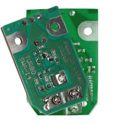
Consider the repair of terrestrial antennas from the repair of antenna amplifiers from the so-called "Polish antennas", using the example of an amplifier Eurosky SWA-2000 fig. 1
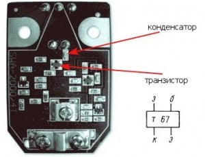
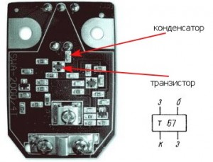
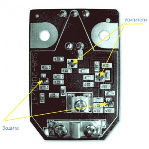
All amplifiers are a two-stage aperiodic amplifier based on microwave bipolar transistors, connected according to a circuit with an OE. For those who are friends with a soldering iron, I think it is not necessary to tell that the amplifier has two stages with decoupling along the power circuit, etc. Let's go straight to practice - during lightning discharges, the transistor of the amplifier of the first stage and the isolation capacitor, which are shown in the figure below, most often fail.
Successful repairs. And let Zeus take his lightning away from you! )
Repair of antenna amplifiers
The repair of antenna amplifiers is usually caused by static electricity (lightning discharges) and a breakdown of the power supply (overvoltage, which rarely happens).
Antenna amplifier is damaged due to a thunderstorm.
Look at the figure with the SWA-2000 amplifier, it shows the transistors involved in amplification and protection (of little help and installed in amplifiers of the 2000 series and above). In case of lightning discharges, the transistor of the amplifier of the first stage and the isolation capacitor most often fail, see Fig.

When repairing antenna amplifiers in the first stage, it is advisable to install high-frequency transistors with an F boundary of 1.5 -2 -3 GHz and a low level of intrinsic noise - Ksh, for example, transistors KT391A-2, KT3101A-2, KT3115A-2, KT3115B-2, KT3115V- 2, the noise characteristics of most amplifier models does not deteriorate, and the use of transistors 2T3124A-2, 2T3124B-2, 2T3124V-2, KT3132A-2 reduces Ksh to 1.5 dB, which improves the parameters of the amplifier. This circumstance allows us to recommend replacing the first transistor of the amplifier with those indicated by the latter, even in serviceable, but "noisy" amplifiers in order to improve the quality of their work.In the second stage, you can use cheaper and more powerful transistors KT391A-2, KT3101A-2 and even the series KT371, KT372, KT382, KT399, KT316 and others with a cutoff frequency of about 2 GHz.
If there are difficulties in repairing, in acquiring such transistors, then you can put the widespread KT399, KT316 in the first and second cascades, while there will be no noticeable deterioration of the picture.
It is better to install new transistors on the opposite side of the board, pre-drilling holes for the terminals with a drill with a diameter of 0.5 ... 0.8 mm. It is better to drill so that the hole touches the edge of the platform.
In SWA amplifiers, both transistors operate with a collector current of 10 ... 12 mA. Such a current is acceptable for the second transistor, but constantly exceeds the allowable one for the first, if transistors of the KT3115, KT3124 and KT3132A-2 series are installed. Therefore, after mounting a specific instance, it is necessary to set the operating point of the transistor VT1. To do this, the microresistor R1 is evaporated and instead of it, a trimmer resistor with a resistance of 68 ... 100 kOhm is temporarily connected. Before turning on the power, the resistor slider must be in the position of maximum resistance so as not to damage the transistor. The amplifier is supplied with a voltage of 12 V from the power supply and the voltage drop across the resistor R2 is measured. By dividing the measured voltage by the resistance of the resistor R2, the collector current is recognized. By adjusting the resistance of the trimmer downward, a collector current of about 5 mA is achieved, which corresponds to a minimum of noise in the characteristics of transistors. Further, instead of a trimming resistor, a constant of the same resistance is soldered.
After that, the printed circuit board and transistors are coated with a layer of radio-technical varnish or a compound to protect it from moisture.
How to avoid such breakdowns, read the article "Why did the antenna amplifier burn out?"
Is your TV, radio, mobile phone or kettle broken? And you want to create a new topic about this in this forum?
First of all, think about this: imagine that your father / son / brother has an appendicitis pain and you know from the symptoms that it is just appendicitis, but there is no experience of cutting it out, as well as the tool. And you turn on your computer, access the Internet on a medical site with the question: "Help to cut out appendicitis." Do you understand the absurdity of the whole situation? Even if they answer you, it is worth considering factors such as the patient's diabetes, allergies to anesthesia and other medical nuances. I think no one does this in real life and will risk trusting the life of their loved ones with advice from the Internet.
The same is in the repair of radio equipment, although of course these are all the material benefits of modern civilization and in case of unsuccessful repairs, you can always buy a new LCD TV, cell phone, iPAD or computer. And for the repair of such equipment, at least it is necessary to have the appropriate measuring (oscilloscope, multimeter, generator, etc.) and soldering equipment (hairdryer, SMD-hot tweezers, etc.), a schematic diagram, not to mention the necessary knowledge and repair experience.
Let's consider the situation if you are a beginner / advanced radio amateur who solders all sorts of electronic gizmos and has some of the necessary tools. You create an appropriate thread on the repair forum with a short description of “patient symptoms”, ie. for example “Samsung LE40R81B TV does not turn on”. So what? Yes, there can be a lot of reasons for not switching on - from malfunctions in the power system, problems with the processor or flashing firmware in the EEPROM memory.
More advanced users can find the blackened element on the board and attach a photo to the post. However, keep in mind that you replace this radio element with the same one - it is not a fact that your equipment will work.As a rule, something caused the combustion of this element and it could “pull” a couple of other elements along with it, not to mention the fact that it is quite difficult for a non-professional to find a burned-out m / s. Plus, in modern equipment, SMD radio elements are almost universally used, soldering which with an ESPN-40 soldering iron or a Chinese 60-Watt soldering iron you risk overheating the board, peeling tracks, etc. The subsequent restoration of which will be very, very problematic.
The purpose of this post is not any PR of repair shops, but I want to convey to you that sometimes self-repair can be more expensive than taking it to a professional workshop. Although, of course, this is your money and what is better or more risky is up to you.
If you nevertheless decide that you are able to independently repair the radio equipment, then when creating a post, be sure to indicate the full name of the device, modification, year of manufacture, country of origin and other detailed information. If there is a diagram, then attach it to the post or give a link to the source. Write down how long the symptoms have been manifesting, whether there were surges in the supply voltage network, whether there was a repair before that, what was done, what was checked, voltage measurements, oscillograms, etc. From a photo of a motherboard, as a rule, there is little sense, from a photo of a motherboard taken on a mobile phone there is no sense at all. Telepaths live in other forums.
Before creating a post, be sure to use the search on the forum and on the Internet. Read the relevant topics in the subsections, perhaps your problem is typical and has already been discussed. Be sure to read the article Repair strategy
The format of your post should be as follows:
Topics with the title “Help fix the Sony TV” with the content “broken” and a couple of blurred photos of the unscrewed back cover, taken with the 7th iPhone, at night, with a resolution of 8000x6000 pixels are immediately deleted. The more information about the breakdown you put in a post, the more chances you will get a competent answer. Understand that the forum is a system of gratuitous mutual assistance in solving problems and if you are dismissive of writing your post and do not follow the above tips, then the answers to it will be appropriate, if anyone wants to answer at all. Also note that no one should answer instantly or within a day, say, no need to write after 2 hours “That no one can help”, etc. In this case, the topic will be deleted immediately.
You should make every effort to find a breakdown on your own before you get stuck and decide to go to the forum. If you outline the whole process of finding a breakdown in your topic, then the chance of getting help from a highly qualified specialist will be very great.
If you decide to take your broken equipment to the nearest workshop, but do not know where, then perhaps our online cartographic service will help you: workshops on the map (on the left, press all buttons except “Workshops”). You can leave and view user reviews for workshops.
For repairmen and workshops: you can add your services to the map. Find your object on the map from the satellite and click on it with the left mouse button. In the field “Object type:” do not forget to change to “Equipment repair”. Adding is absolutely free! All objects are checked and moderated. A discussion of the service is here.
Here in the article it is said which transistors can be put into such an amplifier.
There and about the modes of transistors it is said, but in general, just look like this.
Last edited by Lazy on Tue Sep 21, 2010 07:53:48 AM, edited 2 times in total.
Here in the article it is said which transistors can be put into such an amplifier.
That's right, from myself I can add that in the first stage you need to put a transistor with as little noise as possible. Good luck everyone!
What are common?
It all depends on your capabilities.Your question is too broad.
I don’t know about imports, but our selection is very wide.
It also depends on which channels are important to you. If decimetric meters are not very important, then the choice expands even more.
Here I take a reference book and open it at random.
KT3101A-2
Transistors with normalized noise figure at a frequency of 2 GHz
Designed for use in the input and subsequent stages of RF and microwave amplifiers.
This one will go to DCV
If DCV is not important, then I discovered
KT399A
Transistors with normalized noise figure at a frequency of 400 MHz
Designed for use in the input and subsequent stages of RF and microwave amplifiers.
Those. In the first stage, the keyword “normalized noise figure” at the desired frequency.
And many others. There are a lot of imports. Do not list everything.
By the way, KT372A also has a normalized noise figure at a frequency of 1 GHz in my opinion and a quite good transistor. True, his gain is small.
Since I nevertheless found the reason and sorted it out, I decided to refine this entry. It all started with the fact that I replaced the original car radio with the S150, which I presented earlier. But I ran into the problem of poor radio reception. In principle, I don't even listen to him, but I love that everything works as it should.
On the internet, at one of the specialized forums on this radio tape recorder, I met a lot of negativity on radio reception, and many argued that the reason was precisely in it. But personally, I began to doubt it. Well, I decided to come to the truth after all.
Having met on the Internet a description of the fact that there is an amplifier in the VW Polo antennas and knowing that they need power, I doubted that everything was correctly powered by me. According to the scheme of additional power supply, the amplifier is not, which means that only the car radio itself could power it via the antenna cable. In the originals, this is understandable, but in Chinese radio tape recorders this is unlikely.
But with the Chinese radio tape recorder, so to speak, there was an adapter with power going into it. Previously, not knowing that there is an amplifier in the antenna, I did not pay attention to this fact. but now I'm thinking. The adapter is powered for an antenna or an amplifier. The box is large and too big for a simple galvanic isolation.
And yes, my suspicions were correct. Judging by the elements inside, this is an amplifier. And this means that the power for the amplifier in the antenna does not go. Well, such a scheme is not workable.
Sorting out further, I found from the Chinese clean adapters with galvanic isolation, so to speak, for powering the antenna.
But I said it loudly. These are the Chinese. They save on everything, therefore there is only one capacitor separating the radio tape recorder from the antenna. And such a scheme, to put it mildly, is not effective as it will generate radiation.
Yes, and I did not have this adapter available. And the radio tape recorder is removed. Therefore, I decided to do the denouement myself. To make it, it is enough to have a 1 kilo ohm resistor and a 10000pF ceramic capacitor.
But I went a little trickier. I disassembled the amplifier circuit. Of course, there was no other way to throw the amplifier out of the antenna and that's it, but I didn't want to remove the ceiling just to remove the antenna.
I disassembled, pulled out the board and inserted another one there. In the bins I found a palt with a decoupling for powering a Polish antenna, so to speak. It has been lying around for a long time. The board was in poor condition.
I disassembled it, irradiated it and reassembled it.
I drew a small diagram. If anyone does not understand, I can explain.
Well, I shoved it back into the case.
The result is an adapter with a power supply to the amplifier in the antenna via a wire.
Reception has improved significantly. Mine is happy.
Here I will add another simple scheme, maybe it will be even easier here.
But in connection with the collapse of the Union, the factories that manufacture antennas for television receivers simply stopped producing them. To replace our television production, they began to import imported ones. As our people say, a holy place is never empty. In our markets, it became possible to buy a good imported TV, and in addition, sellers offered an imported multichannel TV antenna at a reasonable price.
The antenna kit included an antenna amplifier and a power supply for it. The antenna cable had to be purchased separately. I did not leave much effort to install the antenna I just bought on the market myself. To do this, it was necessary to have only a tool: a screwdriver, a pocket knife and a wrench.
After installing the television antenna on a specially prepared site, and turning on the TV, we tune it to the transmitting television center. Having adjusted the TV for image quality, the antenna, we fix and fix it so that it does not unfold during strong gusts of wind.
Recently, satellite television has become widespread for receiving television channels. The quality of the received television signal from the satellite, in many respects, exceeds the signal reception from an ordinary all-wave television antenna. Of course, not everyone can afford to buy a satellite dish as we say, and therefore a simple but affordable all-wave antenna with an amplifier is in great demand.
But here's one trouble, during her operation, sometimes malfunctions occur, for one simple reason. During a thunderstorm, we forgot to turn off the power supply from the 220 Volt outlet, and at the same time the TV cable with a plug from the antenna socket of the TV. As a result, the failure of the tuner, that is, the TV receiver, or a lot of expensive radio components burn out.
My advice, do not forget to turn off the TV receiver and antenna from the 220 volt electrical network during a thunderstorm. So you will save not only the TV, but also the antenna amplifier, and in addition your hard-earned money, which could be spent on the repair of the TV.
Next we will have a story about the repair of the power supply unit of the TV amplifier. It consists of a power step-down transformer, a getinax board, four low-power silicon diodes, one electrolytic capacitor, a voltage regulator, and a signal LED.
Most often, an electrolytic capacitor fails in the power supply of the antenna amplifier. This malfunction is displayed on the TV screen in the form of broken lines, and most often you can observe how a black wide strip moves across the image. Immediately, without thinking twice, it is necessary to disassemble the power supply and replace the failed electrolytic capacitor with a capacity of 100 μF, 25 V. In rare cases, the voltage regulator itself fails, which outputs a stabilized constant voltage of 12 Volts at the output to power the antenna amplifier. The nature of the stabilizer malfunction is also displayed on the TV screen in the form of goosebumps or snow.
Anyone who knows how to work at least a little with a soldering iron will have no difficulty in replacing broken parts.
Good luck everyone
Good day!
I have a 2-storey house in Butovo (5 km from Moscow along the Simferopol highway).
I don't really watch TV, so I don't need a plate, and there are several TVs. I bought an antenna “LOCUS” of the “Meridian” series L 025.62 () ”>, fixed it above the roof - 20 channels, almost everything is perfectly visible. About a year has passed, I turn it on - you can see only 5 channels, and on each in the middle of the picture there is a healthy strip. I stick in indoor horns - these are the same 5 channels, but you can see better. We have constant voltage drops, I think the amplifier at this antenna burned out. Tell:
1) Am I guessing correctly and, if so, is it realistic to fix / buy a new one?
2) This antenna with a built-in amplifier, after which a crab is stuck in me and divorced to 4 TVs.The picture is worse than if you directly stick the antenna into the TV. Is it possible to throw out the built-in amplifier and buy an external one, or do you need to change the antenna to a model without a built-in amplifier? Will the picture be better from replacing the built-in amplifier with an external one?
3) If someone would be interested to help not only in word, but also in deed - write, pliz, in a personal with prices.
Thanks in advance for your answers!
- Right. Buy.
- You can throw out the amplifier and replace it with a balun passive device. And install an external amplifier.
- .
This version of a homemade television antenna is the simplest and fastest to manufacture. The maximum number of channels that will be at your disposal is 7, but this figure may vary slightly depending on the region.
To make an antenna for a TV from beer cans, you will need the following materials:
- 2 small screws, also called "bugs";
- 2 prepared beer cans (empty, washed and dried);
- from 3 to 5 meters of television cable (can be taken from a failed device);
- soldering iron and tin (for better fixing of contacts), the presence is optional;
- screwdriver;
- wooden tremp;
- electrical tape or tape.
It will not be a problem to find all the materials in the house, therefore, having prepared them, we immediately get down to business.
In order to make a homemade antenna from cans, you need to follow these steps:
As you can see, the whole process is pretty simple and not complicated. The optimal distance is 75 mm between the ends of the cans, and the best installation location is near the window. In individual cases, the distance between the banks can be made more or less.
Another equally good option that is advisable to use in the village is a homemade copper wire antenna with an amplifier.
All you need for manufacturing is:
- amplifier (fit from an old device);
- two pieces of wire 180 cm each;
- a piece of metal (or wooden) plate 15 * 15 cm;
- an electric drill with a set of drills (or a welding machine);
- small bolts;
- hammer;
- iron pipe;
- TV cable of suitable length.
So, in order to make a copper wire antenna for a TV yourself, you need to follow these steps:
- We prepare the catcher: we bend the wire with a diamond so that all sides are strictly 45 cm (the inventor of the homemade product claims that these are the optimal dimensions of the device).
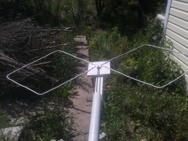
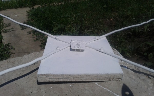
- We fix the wire to the prepared plate: flatten the veins at the attachment points, drill holes and tighten the bolts. If you have a welding machine, things will go faster - you just need to grab the signal catchers to the plate. Immediately you need to connect the amplifier (as shown in the photo).
- We connect the cable. Everything is simple here, tk. you just need to insert the plug into the socket.
- We create a mast, for which we use a metal pipe of a suitable height. We dig it in and the homemade antenna for the TV is ready, you can start tuning channels.
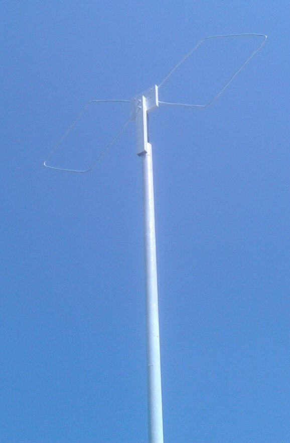
Pay attention - in the photo examples, both the amplifier, and the reflector, and the wire are covered with paint. Painting protects the structure from corrosion and other adverse factors, significantly extending the life of a homemade TV antenna.
If the first 2 options worked at a frequency of no more than 270 MHz, then the next manufacturing method will allow you to enjoy a better picture, because the signal range can reach up to 490 MHz. The only detail that is unlikely to be found among the household trivia is the 300 to 75 ohm matching transformer. You will need to buy it in advance if you decide to make an antenna for your TV yourself as an experiment and improve your skills. Although there are instructions for making a homemade transformer, you can find and use it.


From the materials you will need:
- Scotch
- Cardboard
- Stationery knife
- Foil
- Stapler
- Scissors
- Marker
- Roulette
- Glue
Having prepared this entire school set, let's get down to business!
First you need to sketch (or print on a computer) this diagram:


Now, according to the scheme, we cut out all the parts, including the necessary pieces of foil:


Next, glue the cardboard butterfly with foil and, if desired, paint over the back with a marker.


After that, you need to make a reflector measuring 35 * 32.5 cm (height and width). We glue one of the sides with foil.


In the middle we cut out two identical rectangles, which are necessary in order to completely assemble the homemade antenna signal catcher for the TV. The rectangle should be 3.5 cm long, its purpose is to maintain the distance between the reflector and the auxiliary parts.


We glue the parts on a rectangle, and when the cardboard homemade product hardens, we drill holes for the TV cable.


We connect the transformer and insert the cable into the plug. More powerful TV antenna is ready to use! It should also be noted that this homemade option is suitable only for indoor use, because the paper quickly deteriorates on the street.
Another option for a powerful home-made device:
There is another way to make a powerful antenna for a TV from improvised means, which is suitable for both street and apartment use.
To manufacture the device, you will need the following materials and tools:
- 4-meter copper wire with a cross section of 4 mm square;
- board of any thickness, 55 cm long and 7 cm wide;
- wood screws;
- ruler or tape measure;
- simple pencil;
- screwdriver;
- soldering iron;
- plug.
So, first, according to the drawing, we drill holes in the board:

Then we transfer the drawing data to the board and drill into the corresponding attachment points.

Next, the copper wire must be cut into 8 pieces of 37.5 cm each.

The insulation must be removed in the middle of each of the 37.5 cm lines (as shown in the picture).

We cut off 2 more copper wire pieces 22 cm long and conditionally divide them into 3 equal parts, while at the points of inflection, again, we remove the insulation.

We bend the prepared wire in bare places. We draw your attention to the fact that for those segments that are bent in half, the distance between the ends must be made 7.5 cm (the optimal value for receiving the signal of a homemade television antenna).

Next, we attach the plug to the finished homemade product, and we already connect the TV cable to it.


Here we have provided the most simple instructions. We hope that now you know how to make a home TV antenna with your own hands! We draw your attention to the fact that today on the Internet you can find many other options in which inventors do without cans and wires. Of the rest of the available tools, copper tubes, aluminum discs and electrodes are often used. The advantage of the options we have listed is that you can quickly make such TV antennas with your own hands, without spending the whole evening on it.
Related materials:
| Video (click to play). |


