In detail: do-it-yourself repair of the Vega 10u 120s amplifier from a real master for the site my.housecope.com.
They brought it to the repair quite often with basically the same malfunctions, due to the fact that they tried to "squeeze" everything out of it,
what is possible and even more. I will describe the breakdowns that I had to do most often.
Due to overloads, microcircuits DD1, DA2, DA3, DA2.1, DA2,2 failed most often (k157ud2 - a large signal was applied to the input). To speed up the repair, panels were soldered under them. Instead of transistor assemblies, I selected with the same gain and soldered KT3102 transistors.
Output transistors VT 28-VT30 check for insulation from the radiator.
Check resistors R77-R80 together with output transistors.
Sergey Talmenka
-
unfortunately there is nothing in my pocket, as always. but I want to do it.
Phlanger
-
then we take the sovetskiy pointer avometer, take Borisov's book, cut the fuck out of your internet. True, it will take five years and only horns and legs are guaranteed to remain from the subject Vega along the way, but a solid profit is not excluded at the exit
K. Gereev
-
so it is necessary to study, but then I just asked and everything sings
Bormann
- Sergey Talmenka
Do you generally receive sound after the switch to the amplifier? somewhere there was a pair of dry 10 microfarads and the sound does not pass. Did the conders change the polarity? can you solder? Sukhpayev not done? did not close the paths?
I have a normal soldering iron and learned how to solder from childhood, but it was the electrolytes that I changed all of them there.
It’s not too early to study, and when it’s not too late, but I asked about it and kept singing, I don’t count on it, I know that it won’t sing itself,
Of course, I'm not a specialist, but we don't have them in the village, so I'm trying to do what I can myself (thank God the Internet helps),
So I ask all the proffies where to look after the conductors and transistors, because I checked them all too.
| Video (click to play). |
mart
-
The circuit is in front of your eyes, the sovetsky analogue avometer, as Dmitry advises, should be placed next to the amplifier, the “TON” capsule with a 0.1 microfarad capacitor. For fun, measure the voltage. If it does not work, then simply determine with an earpiece where the signal disappeared in the circuit. And there is a matter of technology.
unfortunately there is only a digital multimeter, and today I will look for a signal with an earphone.
Jupiter5700
-
If all the electrolytes are changed to new ones, but there is still no sound, then, firstly, there is a possibility that the preamplifier has flown out. Give a signal bypassing and check if there will be a sound. Second, check the output transistors. If there is no oscilloscope, then you can drive the entire signal path through the headphones by connecting 0.1MKf capacitors in series to their input.
Andreys
-
Explained 100,500 times.
-We download the scheme. We print. In 3 copies. We take colored pencils and on one we draw how the food goes, with all its pros and cons, and on the second - how the sound goes.
-we take a tester in our teeth and measure the food. Right on the same diagram, we write what is wrong.
- we take high-impedance ears and look at the passage of sound. Directly on the diagram we draw where it is and where it is not.
- we look at the diagram and think a lot.
Andrey N.
-
maybe I'll ask nonsense, the plug is wired correctly.
before there was one plug at work, and at home it was with a different wiring, maybe the wiring where it fell off in the plug, otherwise somehow I did not see about it so that the author wrote
Sergey Talmenka
- Jupiter5700
output transistors checked-working.
Thanks for the advice, by the way, at the expense of a lot, we think this is generally correct.
I checked the cord that I connect from Olympus (they are all standard wiring, it seems like) just in case - everything is in order, on the weekend I will follow the scheme as explained to look and search.
Electron
-
How many domains about this vega have been remagnetized, but still new topics.
Do you think I have not watched them? Everyone has a different problem. but soon we will write legends about Vega.
Phlanger
-
No no no. First, we require a nanny to bring in the dedomorosa, so that he gets it out of the shy rods, or where he hides for himself - old man
so that he whispered over these Voices “daragayaridaktsya. "
and will immediately become shyayte. Well, how is it - a duck in a hare, a grandfather for a turnip. remember?
And if there are no books, no voltmeter, no desire to even understand what it is, one oh! Fagot with these your enturnetame. well, we'll jerk off oh! paminaitminipampeers. "
over 9000 cases
And here is Chyudatvorny Knopaseka “call of the nanny”. I don’t remember who didn’t believe me.
https://my.housecope.com/wp-content/uploads/ext/580/uploads/20160506/1. 892355.gif
Is it from her that the legs of this dementia grow?
Do you think I have not watched them? Everyone has a different problem. but soon we will write legends about Vega.
It was necessary not to look, but to read.
And the problem for everyone who is trying to fix a primitive amplifier by reading forums is the same.
And it will be repeated for YEARS.
Think for yourself, there are two channels. They do not break at once, which means that something in common has broken.
For example - wrong cable or volume control.
Anton Temnikov
-
The case is very difficult. Do you think someone would like to sit with a diagram and treat from a photograph?
Here is the answer to all your questions:
| Video (click to play). |
Sergey Talmenka
-
I study, read, try, search - on the weekend I will continue, I downloaded the scheme in a large size, glued it together, then there’s no time, the vegetable garden is waiting, I’ll rake it up for a couple of days and continue again.
I will write about the results.
Is your TV, radio, mobile phone or kettle broken? And you want to create a new topic about this in this forum?
First of all, think about this: imagine that your father / son / brother has an appendicitis pain and you know from the symptoms that it is just appendicitis, but there is no experience of cutting it out, as well as the tool. And you turn on your computer, access the Internet on a medical site with the question: "Help to cut out appendicitis." Do you understand the absurdity of the whole situation? Even if they answer you, it is worth considering factors such as the patient's diabetes, allergies to anesthesia and other medical nuances. I think no one does this in real life and will risk trusting the life of their loved ones with advice from the Internet.
The same is in the repair of radio equipment, although of course these are all the material benefits of modern civilization and in case of unsuccessful repairs, you can always buy a new LCD TV, cell phone, iPAD or computer. And for the repair of such equipment, at least it is necessary to have the appropriate measuring (oscilloscope, multimeter, generator, etc.) and soldering equipment (hair dryer, SMD-hot tweezers, etc.), a schematic diagram, not to mention the necessary knowledge and repair experience.
Let's consider a situation if you are a beginner / advanced radio amateur soldering all sorts of electronic gizmos and having some of the necessary tools. You create an appropriate thread on the repair forum with a short description of “patient symptoms”, ie. for example “Samsung LE40R81B TV does not turn on”. So what? Yes, there can be a lot of reasons for not switching on - from malfunctions in the power system, problems with the processor or flashing firmware in the EEPROM memory.
More advanced users can find the blackened element on the board and attach a photo to the post. However, keep in mind that you are replacing this radio element with the same one - it is not yet a fact that your equipment will work. As a rule, something caused the combustion of this element and it could “pull” a couple of other elements along with it, not to mention the fact that it is quite difficult for a non-professional to find a burned-out m / s. Plus, in modern equipment, SMD radioelements are almost everywhere used;The subsequent restoration of which will be very, very problematic.
The purpose of this post is not any PR of repair shops, but I want to convey to you that sometimes self-repair can be more expensive than taking it to a professional workshop. Although, of course, this is your money and what is better or more risky is up to you.
If you nevertheless decide that you are able to repair the radio equipment on your own, then when creating a post, be sure to indicate the full name of the device, modification, year of manufacture, country of origin and other detailed information. If there is a diagram, then attach it to the post or give a link to the source. Write down how long the symptoms have been manifesting, whether there were surges in the supply voltage network, whether there was a repair before that, what was done, what was checked, voltage measurements, oscillograms, etc. From a photo of a motherboard, as a rule, there is little sense, from a photo of a motherboard taken on a mobile phone there is no sense at all. Telepaths live in other forums.
Before creating a post, be sure to use the search on the forum and on the Internet. Read the relevant topics in the subsections, perhaps your problem is typical and has already been discussed. Be sure to read the article Repair strategy
The format of your post should be as follows:
Topics with the title “Help fix the Sony TV” with the content “broken” and a couple of blurred photos of the unscrewed back cover, taken with the 7th iPhone, at night, with a resolution of 8000x6000 pixels are immediately deleted. The more information you post about the breakdown, the more chances you will get a competent answer. Understand that the forum is a system of gratuitous mutual assistance for solving problems and if you are dismissive of writing your post and do not follow the above tips, then the answers to it will be appropriate, if anyone wants to answer at all. Also keep in mind that no one should answer instantly or during, say, a day, no need to write after 2 hours “That no one can help”, etc. In this case, the topic will be deleted immediately.
You should make every effort to find a breakdown on your own before you get stumped and decide to go to the forum. If you outline the entire process of finding a breakdown in your topic, then the chance of getting help from a highly qualified specialist will be very great.
If you decide to take your broken equipment to the nearest workshop, but do not know where, then perhaps our online cartographic service will help you: workshops on the map (on the left, press all buttons except “Workshops”). You can leave and view user reviews for workshops.
For repairmen and workshops: you can add your services to the map. Find your object on the map from the satellite and click on it with the left mouse button. In the field “Object type:” do not forget to change to “Equipment repair”. Adding is absolutely free! All objects are checked and moderated. A discussion of the service is here.
Due to the burnt out FU and R97, you have such a voltage imbalance.
Is the R64 really singed? There is nothing to even “warm up” 330kOhm in this amplifier, let alone burn it.
Not R64 but R78. There, on the board, they stand side by side, and the R64 marking is next to 78.
Not R64 but R78. There, on the board, they stand side by side, and the R64 marking is next to 78.
Due to the burnt out FU and R97, you have such a voltage imbalance.
Is the R64 really singed? There is nothing to even “warm up” 330kOhm in this amplifier, let alone burn it.
It's not scary 40 degrees (in fact, 65. 70 is acceptable) - it's scary that in 30 seconds.
I once had - they replaced a burnt weekend, they began to get very hot and soon died again.
It turned out that the bias chain was in the OPEN. Check it out more closely. In your scheme, these are T15 and T16, as I understand from the fragment posted here.
In general, I often practice such a barbaric method - I solder the weekend, connect the speaker with a higher impedance (preferably 4A32) and listen to how the preout works.
If it plays at a low volume without clearly audible distortions, I already carry out a full-fledged launch.
So it turns out to fix it with a little blood, do not burn the transistors in packs.
This should have been done not tomorrow, but yesterday when trying to turn it on after the "repair": because without controlling it when turning it on, you can burn again.
You are inattentive, or you do not read the links given to you - five days ago already. My first, point 9, is about the quiescent current.
“In general, I often practice such a barbaric method - I solder my weekends, connect a speaker with a higher impedance (preferably 4A32) and listen to how the preout works.” - IMHO it's not barbaric, it's quite normal. For the weekend burns first.
Such gaskets are sold in different parts of rubles for three different ones. It's usually easier to buy. Seemingly the price tag is called either “thermal pad” or “insulating thermal pad”. The essence reflects not quite correctly, but the people are not confused.
The thing is really comfortable. Especially in terms of the fact that, unlike mica, it is very difficult to move it. Recently I changed my weekends in K212, I didn't even bother with mica.
Does the adjustment affect the temperature? Is the power imbalance corrected? How does the voltage drop change across R77, R78, R80?
Maybe the preamplifier is dead (K57UD2)?
Are the speakers not killed by the constant at the output when the faulty one is turned on?
I apologize for the question in someone else's topic. I also decided to restore the Vega 10U-120S amplifier. The problem is this, plugging into the network, in the left channel the background to the speaker, the right channel is playing normally. At the output of the left channel, there is a constant of 23 V. As I understand it, almost all the transistors have died? Power supply after diode bridge + 26.2 V and - 24.3 V. There are no obvious burnt-out parts, a burnt-out resistor R97 (it gets very hot within 30 seconds). The amplifier was under a seal, no interference was visible. I replaced the electrolytes on the board, before the electrolytes were replaced, the left channel was also phoning. If, without cursing, I ask for specific tips where to start the check, if not hard, tell me which elements to watch?
In my practice, it was such that the K561LA7 protection microcircuit was stupid, after its replacement the amplifier started working. And in general, the protection in the amplifier is configured to operate from a short circuit at the output of the UM. Feel the terminal transistors, they do not heat up.
Added after 2 minutes
Check the power supply on the 561 microcircuit on the 14th leg should be +12 volts.
Added after 14 minutes
There is also a cunning thermistor attached to the radiator, it also needs to be checked.Immediately replace the C43 electrolyte in the circuit of the D.D1 microcircuit.
Added after 14 hours 48 minutes
If you ask questions, try not to disappear for a long time!
I have the same problem with 5-10 mins shutdown and hang up. It works on overheating similarly (the hand does not tolerate the heating of the radiators).
Before that, he was generally half-alive, one channel worked in a booming middle, the second barely sang inaudibly, replaced all (except 43) electrolytes, 2 channels started working, but began to cut down. The tip shows that someone has already re-soldered it.
Where to dig?
Thanks in advance.
PS I will not be lost, I have been reading the forum for a long time, I did not write simply.
What is it like? Either whole or not. In this amp, everything is extremely simple. You turn it on without weekends, check the zero at the output, the power supply is normal or not, you start up the sinusoid - you look at the oscilloscope, whether the limitation starts evenly when the level increases. Thus, you evaluate the performance of the circuit indirectly, then you seal the ends, carefully check everything. And you check the quiescent current, perhaps you have it twisted to the maximum.
zs This method will not work with Vega 122.
Can you solder by heating a gas soldering iron? if there is no soldering iron. 
Can you tell me how to do without a multimeter?
OSSCIL bu costs 30-40 bucks. Any questions?
Respect to the boy! Doing the right thing.


Mogba and canders and solder the shtob into the board do not chatter on air !! just found a free space, drilled holes and soldered them

yes, it could have been done, but there is nothing to drill with)))))
what would I have to drill))))

Well done, in spite of your youth, judging by your voice, you understand well, but I can't fix the exact same amplifier yet, my mistake was that I didn't immediately check the operating voltage on the transistors, but believed the owner that it was fully working but was buzzing , I changed all the electrolytes, put 6800x50 volts on the power supply, after switching on the output on one channel + 23 volts and on the other -23 volts, while nothing burns and nothing heats up, I also measured about 23 volts on the bases of the transistors of the output units, measured the transistors and the diodes in the circuits of the output stages, everything seems to ring normally, but I cannot enter the mode and I cannot set zero at the output either.
By the way, on the second channel, the constant voltage of 23 volts is the same at the output, I don't understand how he could work with him at all with acoustics of 35 AC
The problem is still most likely in the amplifier itself, on almost all bases of the transistors of the output and pre-output stage 23 volts, I measured the preliminary +12 -12 is, there is no constant voltage at the output.
Tomorrow I will measure it at myself and tell you to write to you about it, but you can see that the tone on one legs is different tension
Good afternoon, I changed all the transistors and the micro-assembly in one channel, although I called the tester more than once before and all the parts called as working ones, after replacing almost all voltage modes did not change. And here is what I measured on the transistor assembly
DA 2 DA 3
1 0.0V 1 0.0V
2 0.4V 2 10.8V
3 0.0V 3 4.0V
4 0.0V 4 11.4V
5 0.0V 5 11.4V
6 0.5V 6 12.0V
7 11.4V 7 11.4V
8 0.0V 8 0.0V
fatoz
Your questions are reminiscent of the "Battle of psychics", only for radio masters. 
You would at least say what the output voltage is ...
When troubleshooting, one should strive to obtain as much information as possible, such as: the resistance of p-n junctions in the forward and reverse directions, the magnitude of the voltage at the test points, etc. At some point, when the amount of information turns into quality, and the whole picture of the defect begins to clear up. Very often in powerful amplifiers, some elements of the circuit, in case of failure, “pull” others.
In your case, we can assume that the output stage is also out of order in this channel, since you did not say that VT14 is heating, but the ULF is working at the same time.
In addition to the output stage, it is necessary to check all the elements of the quiescent current control circuit VT16, VT18 and all the passive elements around. Also, be sure to check the current protection circuit for VT16, VT20, VT22.
How to check? This is a good question and I have an article on the subject in mind. First you need to get a good switch ohmmeter with a relatively large measuring current. Then it is possible with a high probability to check the parts without dismantling.
I don't really like this scheme. For some reason, they saved on penny fuses. Fusible rates must be connected between the poles of the power supply and each terminating ULF. And here we have one fuse included in the break of the common wire. Benefits from him like a dead poultice. I don't know if you replaced him.
Well, and most importantly, do not forget that there are introduced defects in the amplifier, which caused its failure. You said that everything happened after replacing the capacitors. So, these defects should be found, since everything can repeat itself. Check all solders for "snot" and the capacitors for correct polarity. Keep in mind, the actual polarity of the capacitor may differ from the one indicated on the marking. When the capacitor is new, then this can be determined by the length of the leads, and when used, then only with an ohmmeter. In addition, new capacitors may leak too much. If such a capacitor gets into the DC circuit of the feedback, then this can disrupt the operation of the ULF. In our case, this is C27, C28.
Age: 55
Group: Users
Posts: 30 159
Registration: 7.8.2001
From: White Plains, NY
User #: 473
Insert nickname Quote
Age: 38
Group: Users
Posts: 711
Registration: 16.1.2004
User no .: 4 949
Insert nickname Quote
Age: 56
Group: Users
Posts: 5,337
Registration: 9.8.2002
From: Vladimir
User #: 1 679
Insert nickname Quote
I agree, but when you almost get it for free ;-). I bought 4 days ago for 900r Amplifier + 2 speakers (50AS-104) and in quite decent condition. The man did not want to sell separately. And besides, I have a VEGA plant at a distance of 10 minutes. ride a minibus ;-).
Age: 38
Group: Users
Posts: 711
Registration: 16.1.2004
User no .: 4 949
Insert nickname Quote
Age: 39
Group: Users
Posts: 2 628
Registration: 3.9.2003
From: Vladimir
User #: 3 588
Insert nickname Quote
I know I know! They have proven themselves perfectly! We use them to assemble car amplifiers for the general public. They work flawlessly! Take it! If you have any problems with the strapping - ask!
Group: Administrator
Posts: 37 237
Registration: 30.9.2001
User #: 592
Insert nickname Quote
Age: 56
Group: Users
Posts: 5,337
Registration: 9.8.2002
From: Vladimir
User #: 1 679
Insert nickname Quote
I know I know! They have proven themselves perfectly! We use them to assemble car amplifiers for the general public. They work flawlessly! Take it! If you have any problems with the strapping - ask!
I ask;): Firstly, my VEGA has food +/- 25 V. Will it be enough for me? And what will be the output power from this power supply? Secondly, Give a good body kit scheme, and in a nutshell about setting up the scheme, and possible glitches. In the third, the output power of 50-70W is enough for me, but I heard this microcircuit shakes all 100. :
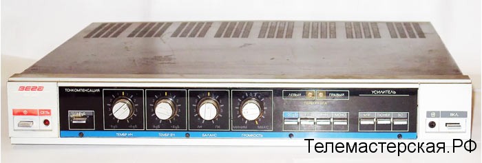
Good day. One of the most popular amplifiers in the USSR is, of course, Vega 10u-120s.
And this popularity is due to the fact that the price of this amplifier was not quite large, the quality (for those times) was acceptable, the dimensions and weight were rather small, and the output power (2x15) was quite enough for listening to the speakers. Therefore, now it is very easy to get this unit, but time and progress are not implacable, since this amplifier can be brought back to life. In this FAQ, I will try to answer the most frequent and exciting questions. =)
1. "I have this amplifier, do I need to change the power supply capacitors to new ones?"
- From my own experience, I can say: Power supply capacitors (4 pieces 5000mF x 25V) dry out in 20-25 years and are no longer suitable for use. I advise you to spend 100 rubles. and buy 2 electrolytes of 10000mF x 25v each and put one on the shoulder. I also want to say that these capacitors are responsible for the absence of drawdowns at frequencies from 50 to 65Hz. It is advisable to supply shunt capacitors with a capacity of 0.1μF.
2. "I have this amplifier, do I need to change the capacitors in the signet for new ones?"
- Here I can only say one thing: It's up to you, if you know how to hold a soldering iron, and at least some experience in soldering, then it is advisable to spend 30-40 rubles. for new capacitors.
3. "When the regulators are turned, noise, squeals, squeaks are heard from the speaker."
-This is an almost inevitable problem, caused by wear on the track of the variable resistor. There are 2 ways to solve this problem:
The first one is to solder these resistors and solder newer ones.
The second, more correct (from my point of view) is to assemble a new timbre block. Personally, my choice fell on the LM 1036n.
4. “The amplifier works, but after a while it turns off, what does this mean?”.
- The thermal protection is triggered, or the thermal diode is covered or the transistors are covered. The price of the issue is from 10 rubles. up to 120 rubles.
5. "If transistors have flown, is there any point in changing them, or is it better to throw them out?"
- There is a sense, the price of transistors 120-130r for 2 pieces, it is not hard to solder (pre-attach to the radiator). It is advisable to buy thermal grease, a gasket between the transistor and the radiator, a bushing.
7. "One of the amplifier channels does not work, both work in mono mode, what's the problem?"
-Most likely the problem is in the area from the signal input to the resistors R9, R10- Regulator unit. You need an oscilloscope, or such a tool:
8. "What transformer is in this amplifier?"
90 watt transformer. 2 secondary windings. Change from windings 2x18v. After straightening + - 23-24v.
9. "Under what IC can this transformer be used?"
- A bunch of! 2x TDA7294, LM3886, TDA 2050 (it is recommended to put 2 diodes for a current of at least 3A after rectification). You can "mix": let's say you need an amplifier 2.1 we hang 2 * TDA2050 and 1 * TDA7294.
There are a lot of options, if you have any questions I ask in the LC, I am always happy to help. )
10. "What if you replace the native tips with an IC, the sound will be better?"
-Most likely not, but the power can be increased unambiguously, but if you try, then the quality can be increased significantly.
11. "What is better to restore or collect yourself?"
- Of course, this is your choice, it all depends on your money and time. For me personally, the ideal, native insides of this amplifier look like this:
But it's up to you to decide. It will take a lot of time, but you will get the full return!
12. “There is no sound from the speakers, only wheezing. What to do?"
- Most likely, the problem is in the signal supply, or the pre-amplifier is out of order, try feeding the signal directly to the power amplifier. If this does not help, then I advise you to study points 5 and 9. =)
13. “The channel output has shorted, the overload has lit up, when the amplifier is“ rebooted ”the channel stopped working, what should I do?"
- This amplifier has output short circuit protection, most likely it is out of order. And now if the overload lamp is on, the output stage is “blocked”. If the channel simply does not work and the overload does not burn, then the exit has flown. transistors in out. cascade.
14 "When you listen quietly (15-20% of the total volume), turn up the volume, overload lights up and the channel is cut off."
- If the amplifier and power supply are in order, then we check the protection unit (made on k561la7 and 4 tnazistors (kt315-361). Usually electrolytes and small containers dry, you need to change all of them, since there are very few of them there.
15 "How much will it cost to repair this amplifier?"
- From 0 rub. up to 500r., with the combustion of 50% of the amplifier. =)
Once again, I repeat that it is better to uproot everything from this amplifier except the transformer and the turn-on LED.
Remember after any modifications, alterations of the amplifier, check 7 times, turn on 1 time! I recommend assembling a protection for your speakers.
From personal experience I can say:
Set aside some time and some money and collect new guts.
TDA2050 is perfect: more powerful, the sound is more pleasant, more compact, less capricious, and the price of the channel will hardly weigh 80-90 rubles.
The tone block is perfect for the LM1036n. (100-130 rubles).
As you can see, the price of restoration is almost the same as that of the one assembled on your own.
In general, good luck to everyone, I hope I helped. Questions can be asked in the LC.
Stereo amplifier VEGA-10U-120S. Schematic diagram of the amplifier and its blocks, photo and appearance of the device.


1. The DC modes indicated in the diagram are measured relative to the common wire (ground) with a Universal 37-25 voltmeter.
2. Individual elements of the circuit can be changed, which should not affect the quality of the amplifier.
3. The alternating current modes indicated in the diagram are measured relative to the common wire (ground) with a V3-38 millivoltmeter when the input (tuner) or (mf) signal with a voltage of 300 mV with a frequency of 1000 Hz of a linear frequency response with the volume control position providing voltage at the amplifier output 9B.
In general, it is not recommended to install any EH and their analogs such as 7812 (7912) for powering preamplifiers and timbre blocks. The fact is that these stabilizers can generate noise that is transmitted to the op-amp. There are more than enough cases when people put super low-noise op amps, power them through 7812 (7912), and then wonder where so much noise comes from.
In radio number 10 for 1990, Sukhov published a timbre block diagram for a high fidelity amplifier. In the attachment is a part of this circuit with a power regulator for microcircuits.
Unstable voltage +/- 30-45 volts is applied to pins 19.21 (pin 20 - common power wire). The circuit will work at a lower voltage, but it will be necessary to reduce the resistors R38, R39 to optimize the zener diode current. The voltage of +/- 12 volts is removed from the capacitors C22, C23.
The scheme is similar to Veg's, only on other details.
Considering that there are only two op-amps in the Veg's tone block, the circuit can be simplified. The transistors are removed, the zener diodes are replaced with others with a voltage of 12 volts (you can leave these as well). The voltage to the zener diodes is supplied through current limiting resistors. The resistors are selected so that the current through the zener diodes is about 5 mA in operation. Heating of these resistors is possible, so they must be selected for a power of about 0.5-1 watts.
I propose a variant of the improvement of the Vega 10U-120S amplifier.Many people complain that this amplifier has an increased background level, and a pop is heard when it is turned on. How to reduce the background in Vega 10u120s, how to modify the power supply and get rid of the constant at the output - I'll tell you about all this in this video. And of course, let's check the maximum power of Vega 10U-120S, whether it has the declared 25 watts, and a little wiretapping.

I would not criticize so much technical solutions 25 years ago. The Vega plant had a side production of "consumer goods" (there was such a term) and a limited ceiling on cost in the amplifier class specified by the State Planning Committee of the USSR. As a result, we got an average amplifier for those years. If done on a conveyor belt in a stream, as the author would like in the video, then it would be a different price and an amplifier of a higher class, such as Odyssey, Afmiton, Brig. But these amplifiers were made by other radio factories in the country. The factories in the days of the USSR had no choice what to do and in what class. This was decided by Moscow, and all enterprises were obliged to fulfill these plans. Enterprises did not have economic freedoms as they do now. I agree that idealizing the USSR is now not correct and there is nothing to do

Horror. this is not a revision and repair, this is a blooper from a lazy dropout.
My friends and I had such amplifiers in our youth, and now we have one in the garage, and I tweaked it very specifically. I consider the amplifier circuit to be very advanced at the time, especially the absence of a relay and a complete electronic protection circuit. This amplifier has two problems - drying electrolytic capacitors and contact loss in the power diode mount.
The one in the garage has been specifically reworked and even the metal cover has been repainted and all the plastic has been washed and restored.
In my amplifier, I left DIN5 in place, the phono stage at the input simply converted into a buffer amplifier with Ku = 1, otherwise the timbre block will not work correctly. I converted the -6dB button to DIRECT - full bypass of timbres.
I also reworked the power amplifiers a lot, in the power supply unit I installed two more containers of the kind "with a twist". I made a different exit - it immediately goes to the new terminals for acoustics, bypassing the switch on the front panel.
The output power is quietly 2x25x4Ohm for a long time and with decent sound quality.

everyone is so straightforward "sophisticated" now. And when there was not much choice, they listened and praised more! How many opportunities did someone have in the late 80s and especially the 90s to buy a company? It's fashionable to find fault with everything old, especially Soviet. And it's fashionable to use “great” brands with Chinese stuffing inside-))))

Well, criticism is about nothing. This is not a revision, but a collective farm.

I don't understand why take an amplifier, modify it, and then pour shit, immediately take Chinese and say - "Guys a fucking amp"
And replace the electrolytes of 20 (30) years ago on the main board.

not overheating protection is mounted on the radiator, but thermal compensation of the quiescent current.
Author, this is not a revision. In fact, nothing has changed much. To do something in order to “decrease” the background and close our eyes to the constant at the output. I don't see the point. It's good to read the info about someone else's revision, but you also need to figure out why this revision improves the quality, and not just repeat and wander in the dark. IMHO, wasted time.

Test acoustics on voiceless. "Pop singers" 0_o - arrrriginal! Moreover, the music is there. well, like music. of the same order.

The Vega 10U-120S amplifier is a budget amplifier, it cost less than 200 rubles. It is an improved continuation of the amplifiers that were on the Vega 104, 108, 109 electrophones. Clicks when turned on are a consequence of the lack of relay protection. The background can be of a different nature as a result of malfunctions, the reasons may be external. And for the money that it cost, it was 100% consistent, whoever wanted better bought more expensive devices. As for your revision, this is most likely a cut in its capabilities. The switch in the amplifiers was needed to switch different inputs from different sources, in those days it was necessary, in modern times the source can only be a computer.The other day I bought one for myself, replaced only the K 157-UD2 microcircuit in it at the input, checked the capacities on the power supply unit and the whole amplifier worked as it should, slightly only the regulators are repetitive when adjusting, but it doesn’t matter.

Low capacitance of rectifier capacitors
Fuse for common ground (!)
Thin power wires
weak output stage (well, there is enough space, and trance also has a margin)
bad getinax, very bad
wacky dash-dot jacks
Curved input circuits, long signal path
redneck tone block
unshielded signal wires
protection curve, in fact not protecting the speaker normally
I don’t remember, but with the layout of the land, it’s also not very good
about the P2K input selector and the "correcting amplifier" - I think it's clear
switching speakers through a button for headphones (.)
What did:
Replacing all power wires
Replacing the rectifier condensers, increasing the capacity
Installation of a modern diode bridge
Output signal jacks to RCA
direct signal cables from the jacks to the input conder of the UM (the wires with the signal from the amplifier are stupidly removed), that is, direct input
Jumpers instead of a cable for headphones
Installation of LM7812LM1912 for 12V stabilization
Replacing all electrolytes, increasing capacities (where necessary)
replacing low-power transistors with imports (don't ask, I experimented)
setting the quiescent current and constant at the output
replacement of trimmers with imported
I replaced the dot-dash with ordinary terminal blocks with screws (which was at hand)
I also remember the days off for some reason I changed, there were 8101 and some others, but I changed to 818819
Replaced mica and thermal paste, modified fasteners
After all the improvements, the sound became good.
But the power was still not enough.
I did something with the output stage, but then I was still not so smart. burned down the defense.
Got stuck (
All the good parts were removed, and the main board went to the trash.
I put the tone block on the details.
Then I had to make an amplifier for the urchilis, in the urchilis, my colleagues had already made good boards for the TDA20302050 in advance.
Well, then I went and bought the original TDA2030 (at 4, 70 UAH at that time), a good strapping, and so on.
I managed to implement double mono (you can't forbid living beautifully), due to separate rectifiers and windings.
I made a new back panel, cut a plate out of tin (the simplest solution).
Installed inexpensive spring-loaded clamps - enough for this power.
I also finalized the muzzle, removed everything and neatly repaired the holes.
I took the radiators for TDAs more clearly, made a mount for the case.
The signal cable was still some kind of thieves at hand, it is clear that it was directly from the jacks to the input conductors of the UMZCH boards.
Power wires are moderately thick and moderately short.
So this was my first microcircuit VCL.
And when I heard how the microcircuits sound for Kitsya Alisa

Thank you for the video and for your constructive criticism of the amplifier. And then the people have superstition - if "made in the USSR" then it's incredible cool with transcendental quality.

I looked and realized that the author of the video does not know anything about audio equipment at all. They ripped off a lot of text and general phrases from the site, and carried out operations invented by someone underdeveloped there. I have had such an amplifier paired with 007 amphitons for three years now, and they all work out awesome. And I can't stand the comparison of Chinese watts with Soviet ones. Clap when you turn on this is all amplifiers do, you just need a delay system to do. And the so-called "background!" the measured out mind, it is not exposed to 0 on the way out. And the cable that so be it. Hands should be straight and smart to read books.

comparing the aaparatura of this year and the vega of the last century is not adequate
what I would take from him are radiators .. and a transformer

These amplifiers, unfortunately, suffer not from sound quality, but from build quality. but Tda were not lying around.

dislik - you just got fucked up

before the music was completely different, but for that time this amplifier was good. It's silly to compare the amplifier of the early 90s with modern China.
Well..pa, not revision. The only thing that makes sense to do there is to make protection on the relay without spoiling the standard design.

Hum from poor contact of the diode with the board, under the nut


