In detail: do-it-yourself sony video recorder repair from a real master for the site my.housecope.com.
VCR POWER SUPPLIES
VCR repair site:
Replacing video heads:
Configuring the LPM path:
———————————————————————————————————-
VCR head cleaning devices are made from different materials, but mainly foam rubber is used. Over time, the material of the cleaning roller becomes dirty and causes problems in itself. The decomposing foam rubber sticks to the drum and mechanism parts, this leads to the appearance of various failures in the belt pulling path. Several options for the manufacture of new cleaning rollers have been worked out. The one described below is, in my opinion, the most affordable and technologically advanced.
At the end of a piece of wire 20 - 25 mm long, 0.8 - 1.2 mm in diameter, a ring is bent on a suitable blank (drill, for example), taking into account the outer diameter of the future roller. The rest is used as a pen. It turns out something similar to a device for blowing soap bubbles. The annular part is glowed red on the burner flame. Then it is quickly carried out along the entire length of a suitable piece of foam rubber. It turns out a long cylindrical sausage. Which is then cut into cylinders of the desired height with scissors. The inner hole is burned out with a heated suitable drill or soldering iron.
——————————————————————————–
Floppy disks have white spacers. From a tube from a telescopic antenna of a suitable diameter with a sharpened edge on hard rubber, you stamp circles, type a bag, clamp between metal plates and drill with the desired diameter. ALL.
| Video (click to play). |
Maybe someone knows why the software bar breaks, but I will share it all the same.
Due to long-term operation in many video cameras, contacts coordinating the position of the program strip are oxidized and burned, as a result of which the control engine does not stop at the right moment and, "crack",
The bar is cracking. At first I reinforced the bar with a metal plate, it helps a lot.
Then I got to the contacts.
For those who have heard something about chemistry and electrolysis.
I can suggest silvering contacts.
For my video player, I did just that. Already the 5th year has gone, everything works fine.
If anyone is interested in how this is done, write. I will always be glad to help.
Rottor
The fact that the bar breaks because of a dirty programmer is true.
In any case, practice has shown that someone who changes the bar and does not clean the programmer will change it again in the near future. 
Just for the reason described above (the engine does not stop at the right moment).
Of course, if the bar was made taking into account such loads, it would not break.
The shank on the motor axis bursts for the same reason and quite often. It seems to me that washing with alcohol without disassembling the programmer is ineffective. Usually I clean the collapsible ones with a soft eraser for a pencil, and it is better to change the non-collapsible ones.
I still do not quite understand why IT needs to be changed and disassembled. There is no dirt there, there is dried grease, sometimes pitting corrosion in some points. Spring contacts generally retain sufficient force. Existing cleaning sprays and liquids completely solve cleaning problems. But the use of oil in combination with gasoline is just as effective and completely restores the operation of contacts. The problem is that flanges on the stator and rotor of the program switch interfere with the penetration of liquid into the contacts. It is enough to unbend the plastic parts of the programmer with a thin screwdriver, which will ensure the penetration of cleaning liquids into the interior without hindrance. Simple and reliable method does not require much time and disassembly
By the way, in this node there is another jamb laid down by the designers - try to rotate the gear and see how it clings with the stiffener of one of the grooves in one of the positions for the axis of the bar, bending it just at the point along which the break always occurs.
But I don't want to reduce the length of this tooth (?) And have not tried it.
Why should you shove sticks in your wheels?
VCR malfunctions table .
PICTURE OF THE TITLE SHEET OF THE MANUAL.
TABLE OF FAULT CODES.
The code on the display of the PANASONIC K-mechanism vidacs.
one). U10 Dew formation
Wait until the indication disappears.
2). H01 After cylinder lock is detected, the cylinder does not start rotating again even after tape unloading.
Check the cylinder-motor drive circuit.
3). H02 Cassette tape is not wound up during tape unloading except Eject mode.
Check the capstan-motor drive circuit.
4). F03 Mechanism locks during mode transition except Eject mode.
1. Check the loading-motor drive circuit.
2. Check the mechanism phase alignment.
3. Check the Mode Switch.
5). F04 Mechanism lock during tape unloading.
1. Check the loading-motor driveї circuit.
2. Check the mechanism phase alignment.
6). F05 Cassette tape is not wound up during tape unloading in Eject mode.
1. Check the capstan-motor drive circuit.
2. Check the Supply / Take-up reel pulse.
7). F06 Mechanism locks after tape unloading in Eject mode.
1. Check the loading-motor drive circuit.
2. Check the mechanism phase alignment for Cassette Holder Unit.
eight). F09 No serial clock transmission between IC6001 and IC7501.
Check the serial clock circuit.
Here is the same in Russian, and even with pictures.
Often it is a mechanical button or a contact group that is the cassette loading sensor.
You insert the cassette, press => the elevator moves, directly or through mechanics, presses / depresses the button (closes or opens the contacts of the contact group) (or the cassette itself acts on the key) => I / m activates the engine, which lowers the elevator / pulls the tape onto the drum. The impact on this key must occur at the time of loading the cassette, before the lift and belt tensioning system are activated.
As for the S101, it is a cassette recordable sensor. You should have it in the place where loaded cassette has a protective tab. If true, then it is not a cassette loading sensor.
P.S. I have practically no experience in repairing VCRs, I can not give valuable advice. Only what I encountered myself.
Added by (16.07.2014, 20:25)
———————————————
Regarding the S101: another manual, recommended in the original, says that this button serves both to check the tape for write protection, and to recognize the tape in the deck.
For the additional manual - thank you, very valuable!
"Button" - you are right, - I will check, in any case it is necessary to check everything, that at least some suspicions!
The next step is mechanical. button - it is the cassette loading sensor;
then after it it is necessary to check the worm "cam-motor" how the signals come to it.
Added by (17.07.2014, 18:10)
———————————————
Mechanic I checked the button - ok.
In general, I decided the other day to check the CAM-motor and the IC130 (LB1943N) controller that controls it, pages 4-17,4-18 according to the manual, MA-401 (SERVO / SYSTEM CONTROL) SCHEMATIC DIAGRAM. And here's what happened:
Measured relative to the mass - 1.3nn IC130.
voltage: (indicated according to the diagram), c / w fraction: dir. wait / try to start
- 2n (2V): + 0.25 / + 9.4V
- 4n (2.3V): + 2.1 / 0V - this is, as I understand it, control from the servo controller, from 33n.
- 6n (4.8V): + 4.8V
- 8.9n (13.6V): + 13.8V / + 13V
- 10n (0.2V): + 0.1 / + 0.4V
As a result, it turns out that at the CN104 connector of the CAM motor, a positive voltage should be supplied to the 3 pin (CAM +) relative to the 1 pin (CAM-), and it turns out that a voltage of reverse polarity is supplied, -9 V., i.e., to (CAM-) : + 9V, on (CAM +): -9V.
At the moments when voltage is applied to the motor (albeit in reverse polarity), it makes absolutely no sounds! Continuity of the motor contacts without disconnection shows a resistance of 13 (Ohm) between CAM- / CAM +
Now how to understand what the problem is, with the CAM controller IC130 or with the CAM motor M903.
Here, I spread the page: 
Added by (17.07.2014, 19:22)
———————————————
CAM-motor removed-checked, turns in both directions.
That leaves either the CAM controller or the mechanics.
But with mechanics - a dark forest.
1.How does the i / m react if this button is pressed in the on state?
is this the measurement result between the 2nd and 10th feet of the IC130?
the motor is turned off (the connector is soldered or disconnected) and without the motor in the circuit, measurements are again carried out (1-4 and 2-10 legs of the driver), with the button released and pressed.
3. And I can't understand everything about the button: does it signal that the cassette has already been loaded, or is it activated at the moment when the cassette is inserted manually, but has not yet been loaded by the lift?
I still do not quite understand why IT needs to be changed and disassembled. There is no dirt there, there is dried grease, sometimes pitting corrosion in some points. Spring contacts generally retain sufficient force. Existing cleaning sprays and liquids completely solve cleaning problems. The use of oil in combination with gasoline also effectively and completely restores the operation of the contacts.The problem is that flanges on the stator and rotor of the program switch prevent liquid from entering the contact area.
It is enough to unbend the plastic parts of the programmer with a thin screwdriver, which will ensure the penetration of cleaning liquids inside without hindrance.
Simple and reliable method does not require much time and unnecessary disassembly
Monitor's Killer
Posts: 3756
Monitor's Killer
Posts: 3756
TABLE OF FAULT CODES.
The code on the display of the PANASONIC K-mechanism vidacs.
one). U10 Dew formation
Wait until the indication disappears.
2). H01 After cylinder lock is detected, the cylinder does not start rotating again even after tape unloading.
Check the cylinder-motor drive circuit.
3). H02 Cassette tape is not wound up during tape unloading except Eject mode.
Check the capstan-motor drive circuit.
4). F03 Mechanism locks during mode transition except Eject mode.
1. Check the loading-motor drive circuit.
2. Check the mechanism phase alignment.
3. Check the Mode Switch.
5). F04 Mechanism lock during tape unloading.
1. Check the loading-motor drive circuit.
2. Check the mechanism phase alignment.
6). F05 Cassette tape is not wound up during tape unloading in Eject mode.
1. Check the capstan-motor drive circuit.
2. Check the Supply / Take-up reel pulse.
7). F06 Mechanism locks after tape unloading in Eject mode.
1. Check the loading-motor drive circuit.
2. Check the mechanism phase alignment for Cassette Holder Unit.
eight). F09 No serial clock transmission between IC6001 and IC7501.
Check the serial clock circuit.
Here is the same in Russian, and even with pictures.
Reference books and information on video heads.
VIDEO HEADS BY MODEL.pdf 65,11 KB Downloaded: 8094 times
MODEL HEAD ANALOG.pdf 61,15 KB Downloaded: 4703 times
Modification of the tensioning mechanism.
- The problem arising with the tension of the tape with a weakened friction of the braking device is solved with a weak alcoholic solution of rosin and oil.
- A small amount of oil (10 - 15%) is required to ensure even friction.
- Put a few large drops of solution into the indicated sector, turn on the mechanism for accelerated playback for 1 - 2 minutes, then rewind the tape several times in different directions, until the remaining solution dries and stabilizes.
- After the restoration of the operability of the automatic tension adjustment unit, as a rule, it becomes necessary to re-adjust the position - the height, inclination, azimuth of the CZG, to ensure the normal position of the tape on the guide columns, and the correspondence of the position of the heads in relation to the tape.
– BUT, first of all, by adjusting the slope of the SZG, the lower edge of the tape is “abutted” against the guide column limiter (to the left of the rubberized roller), controlling the absence of warpage, which ensures the standard mode of “jamming” of the tape on the guide columns and excludes its vertical displacement .
- In this case, it must be borne in mind that “rosin-alcohol solution” is not a concentrated soldering flux!
Wanderer
Posts: 6013
Panasonic NV-SD3, NV-SD10, NV-SD11, NV-SD20EE and etc.
The defect looks like this, when receiving from the tuner on bright scenes, the horizontal synchronization is broken (the image seems to break vertically), and at the LF input when a signal of color stripes is applied, the vertical lines of color transitions have a zigzag line. When checking such a signal with an oscilloscope, you can see that the horizontal sync pulse has changed its duration, instead of the intended width, it has only a vertical pod!
And when playing a cassette, the result is no better, also a broken image, as if the video segments / heads are dirty, it will not work to rinse, and there is no need to twist the racks to the point of stupidity, it will not help!
The defect lies in the surface mount aluminum capacitors on the hybrid assembly. VEFH29B signal processing unit, there are 5 of them (3.3x50v, 4.7x35v, 10x16v, 10x16v, 47x5v) I advise you to replace everything at once, there were blocks where all the containers "died".
I recommend sharpening the tip of the soldering iron (for dismantling), and select its power at least 40 or 60 W and work carefully, because the ceramic substrate.
When selecting conduits for replacement, take into account the parts installed on the main board under the assembly or you will have to redo them. It is possible to select containers not strictly. +/- 10-15% is not critical for normal operation.
Restoring a belt in Samsung SVR-405
The SONY player does not give up the cassette, playback and rewinding are unstable - the contacts of the programmer are dirty.
SONY series 4xx, 7xx. During operation, when the cassette is ejected, the processor "freezes", all settings are blocked, the cassette does not come out of the cassette receiver, the device must be switched off-on. It is necessary to bridle the terminals of the loading motor to the housing with capacities of 0.1mF.
VM SONY SLV-E400 It has already been written about the low quality of the trimmer capacitors installed in the SONY equipment. Another example. The VCR does not function as a monitor, i.e. does not transmit the signal from the tuner to the output, the output is a constant blue background with OSD signals, although this signal is recorded perfectly, the signal also passes through normally during playback. Signal generator and video signal switching is performed in the OSD block, made on LC74790. Here is the ill-fated trimmer with the number CT601 (AFC). Washing it with alcohol gives an effect for several days, so it is necessary to change it, it is better to ours, domestic, they say there is more silver in them 🙂
SONY SLV-X711 After inserting the cassette into the cassette receiver, the vidic feeds the tape, stretches 5 centimeters, stops and returns the tape to the cassette. When you press Play or rewind, the process repeats. After 3 to 5 attempts, it generally unloads the cassette. After observing the process, I noticed that the rotation speed of the BVG in the process of refueling increased to such an extent that the reverse rotation of the BVG was visually observed. Rotating the BVG with an oscilloscope checked the presence of pulses on the hall sensor, normal up to 1.5V. Suspicion of the engine control microcircuit BVG MS VA6415FS. Replaced it and it worked.
VM SONY E400 - does not catch the transparent tape of the beginning and end of the film. The central LED turned out to be operational, it is controlled by the CXP87248 processor (37 feet) through the key, apparently to increase noise immunity, since Constant illumination of the side-mounted phototransistors has no effect. The processor output turned out to be set to zero, but the client did not want to change it. the malfunction is not critical, although a sharp dynamic impact at the end of the film during rewinding can damage the crystal of the video head, but as they say, the owner is a master. Although you can try to simulate pulses from an external generator of the simplest. I tried a meander at various frequencies, it didn't work. Apparently it is necessary to know exactly the frequency and duty cycle, who can come across a worker - look, I will be grateful.
Video player SONY SLV-P51, typical failure. Manifestation: after the film starts to move (any mode - playback, rewind, fast scans in both directions) the device “freezes” - it does not respond to any commands either from the remote control or from the keyboard. After disconnecting from the network, or forcibly resetting the control processor, the functions are restored before the tape starts to move. It turned out to be very easy to check the assumption that the processor is hanging by static from rubbing plastic parts - slightly raise the board - all functions were restored. The processor is located very close to the pressure roller, which was quite dirty, the grease in the bearing is dry, it is enough to rinse it with alcohol and lubricate, and the percent. additionally shield with a piece of foil so that it does not repeat itself in the future.
SONY video player - from time to time after switching on, it may stop seeing that a cassette is being inserted into it. In the PSU, the 24V Zener diode holds 28V. Because of this, the processor power is instead of 5V 5.9V. After replacement, the second breakdown: the engine of the tonal drive may not start, on the engine board you can see drips under the electrolytic capacitor. And a slight burning smell. I changed it, everything works.
SONY SLV-286EE (and also SLV-436EE / X311 / X711). TV channels are not memorized, although the tuner is tuned in the usual way. But after exiting the setup and switching the program, the newly configured program disappears. At first glance, the reason seems to be in the EEPROM memory, but do not rush to change it (especially since the original microcircuit is difficult to find). The reason lies in the IC501 system processor (100 pin chip).Its part responsible for the exchange with the tuner and memory is suspended. It is necessary to zero the signal at pins 53, 54 and 89, 90 (they are connected together) by shorting them to ground (ATTENTION: this must be done with the power off). At the same time, capacitors C512 470x6.3V and C505 100x6.3V are discharged and the processor returns to normal mode. Previously stored programs are restored. This move prompted me at the conference Dmitriy to whom we are enormously grateful.
The SONY SLV-E450EE VCR lacked control from the remote control, it was fully controlled from the front panel.
In an authorized SONY service center, the uPD75304GF percentage located on the control board (1-650-832-22) and the CXP87248-013Q processor on the main board were changed, but the result remained the same and the device was returned to the owner.
A detailed study of the modes revealed underestimated (about 2-3 V) voltages at the IC1 pins (uPD75304GF). Upon further check of the elements, a 5.1V Zener diode (pos Q13) was found in the leak. After replacement, the functionality is fully restored.
SONY SLV-X57 - loads the cassette, the loading motor continues to rotate for some time after loading and then the cassette is unloaded. The tape does not feed. I check the motor and driver chip (LB1641) - everything is in order. (The driver checked by feeding control levels from a conventional tester directly to the mikruhi terminals. 5 and 6 feet. The level should be higher than 2 volts according to the datasheet. If you apply it to the 5th leg, then the tape filling mode is activated, on the 6th - the opposite action.) Checked photo sensors - everything is OK too. I drew attention to the unit where the cassette loading drive mechanism is located. There are two contact sensors. One is end, the other is a 3-position slider. It turned out that the lever controlling the 3-position switch jumped up along the axis, apparently due to the weakening of the latches, or someone “competent” had already climbed there. I put it in its place and it worked. A similar malfunction later came across in a device with a similar kinematics (SONY 711 like. The one that ProLogic with a folding front panel) Only in it the cassette did not want to load at all. It turned out that in the same node at the lever that moves the slide switch, a spring jumped off on one side and the slider moved to the extreme position.
SONY SLV-X57 - no color in PAL. Upon visual inspection of the board, YC saw that one leg of the X1 quartz (4.43MHz) was soldered. Restored soldering and color in PAL appeared.
SONY SLV-XC10SC. Spontaneous switching of speed capstan SP-> LP. After warming up for more than a minute, the malfunction disappears. Replaced the BU2586 processor: to no avail. Fault in the power supply. Replaced the capacitor C5101 470μF X 16 volts. Everything returned to normal.
Sony SLV-X312 gear crackling at the end of rewinding, the letter “L” appears on the display, and automatic rewinding at the end of the tape also does not work. My optics have been removed from yellow plaque, and everything is ok ”. Yes, you still need to tell his owner that smoking harms not only his health, but also his pocket.
Video deuce Sony KV14 MV Vidak did not load the cassette, went through the loading block, i.e. all contacts are correct. Began to download. Tightens the tape and, as if there is no signal to stop the loading engine, the engine hums for 3 seconds and unloads the cassette. The programmer cleared it - it did not help, it turned out to be necessary to shift the program gear itself from the mark on it by one tooth. Everything became normal. And they also complained that the TV set itself turned on, turned off itself. While I was digging in the video recorder, this was not observed, and then it stopped, you can see some kind of connectors oxidized. Actually, the deuce - part of the video is very inconveniently made for repair. Put it on the table immediately, and take all the cords and cables out through the holes, and connect the tape drive mechanism there.
Walkman SONY GV-A500E PAL Portable VCR One malfunction has appeared: the “Drop” icon appears on the screen and the error “From 21 00” blinks, which means moisture condensation in the mechanical part.Drying the device does not help, and the “Drop” still flickers. Immediately imposed on the idea that a bad moisture sensor. But as the analysis of the circuit and the board showed, this is a factory defect, it turns out that this very sensor is not connected at all. To eliminate this defect, you just need to put a jumper on the board from the bottom side.
Design and support:
Aleksandr Kuznetsov
Technical support: Mikhail Bulakh
Programming: Danil Monchukin
Marketing: Tatiana Anastasyeva
Translation: Natalia Kuznetsova
When using materials from the site, a link to https://my.housecope.com/wp-content/uploads/ext/3265 is required
made in Ukraine
Secrets of repairing VCRs 1
Fault: There is an automatic switch from stereo to mono.
Remedy: Perform manual tracking adjustments in one direction or the other, if the device stops switching, then the synchronizing head is probably not precisely adjusted. Change the position (height) of the tape guides located on the left and right of the drum with video heads.
Fault: When the tape recorder is operating, the cassette ejection button is pressed and the tape recorder tries to perform the operation, but, without completing it, freezes and all buttons are blocked. After turning off / on the power, the cassette leaves.
Remedy: The controller may be dirty. It is located underneath the tape drive. It should be removed, washed with alcohol, lubricated and collected. Or the loading / unloading device is faulty. The bushing bursts on the shaft of the loading / unloading motor, it starts to slip and the device enters the blocking mode with an error indication on the display F03. It is also possible that there is arcing of the contacts of the brushes on the collector of the load motor, which leads to the processor freezing, then it is necessary to bypass the leads of the load motor with a capacity of 0.1 microfarads.
Fault: Arbitrarily goes into standby mode, the cassette is not ejected.
Remedy: Clean and lubricate the programming gear.
Fault: On the TV screen, wide white stripes of 15-20% of the image size are dropped vertically, lines are knocked out, sound is floating.
Remedy: Damaged high-voltage capacitor at the output of the diode bridge on the mains input of the pulsed power supply unit.
Fault: During playback, auto-tracking does not stop (it constantly works, passing the optimum), therefore it plays back with varying success
Remedy: Check the signal flow from the sync head. Possible poor contact, head contamination, open circuit in the loop, dried electrolytes, whether there are mud rims on the drive motor shaft, etc. If the bushings on the drive motor are broken, then the tape can “walk” up and down the sync head or even go above it ...
Fault: When loading a cassette, there is a periodic loading and unloading. When removing the top case cover, the video player works normally
Remedy: The central infrared sensor is out of order.
Fault: At regular intervals (10 seconds) the tape stops in the tape recorder in all modes as during playback, recording, rewinding.
Remedy: Check if the pause is disabled in the pause mode. If not, then most likely there is a problem with the reel sensor (paddle pad motion control sensors). It is necessary to check its power supply circuits, whether it is clean (optocoupler), clean the reflecting sectors on the pad holder. The sensor may need to be replaced.
Fault: All functions work except tape rewind. When you turn on rewind 2-3 sec. the engine is heard, after which it turns off
Remedy: Clean the command device.
Fault: Video and sound playback is normal, but if you put the device into standby mode and turn it on again, noise appears in the image at the top of the screen or at the bottom, or there may be no image at all, while the sound is normal.
Remedy: Replace the Hall sensor in the BVG.
Fault: Some time after the start of the run, the apparatus stops, after that it does not respond to any command. After a complete shutdown (everything is restored for a while), and then everything is repeated from the beginning. Cleaning the programmer did not give anything.
Remedy: Check the power supply of the device as a whole. It is possible that the capacity in the secondary circuits has dried up, in the rectifier, especially 5 V), or in the primary rectifier of the power supply unit. Protection in the power supply can be triggered. High-resistance resistors, inductors, capacitors should be checked. Check control power supply. It is possible that there are cracks in the conductors on the board at the points where the broach is attached.

See other articles of the Repair Secrets section.
Hey! Let's make friends with channels.
Check the hardware, almost all of them were made of brass.
✋ In the summer, I took apart a similar video camera. In the "head" of the valuable - the head itself. I handed it over for acceptance with an aluminum mix, though I had to tinker with the second half - I worked at home, and a vice in the country. It was difficult to pull out the stock
hello wonderful channel thumbs up friendship hope for reciprocity friends
I had one. I offer a mutual subscription with mandatory open channels and, of course, video views. Maybe we will recommend the channels to friends. Let's wait.
Sasha, of course, I am always not against friendship, but I will probably not be of interest to you as a subscriber. I don’t just play tanks, but I don’t play any computer games at all))) I don’t know how and I don’t want to kill time for it, as there are many other interesting things to do. So, see for yourself.
You asked how to sign up with us? Very simple! write to my mail - let's write it off by mail, just send me a song and we will arrange
And how much will it cost?
Kolya, I beg your pardon. I convey my regards to you in Latvia and not in Lithuania. To my friend Nicholas, for consultations. I'm waiting for an SMS to Odnoklassniki. I wrote to you yesterday and you weren't online.
still did not understand from which channel and whose SMS was removed? I'm in my classmates now - let's talk.
Yes no. Everything in the computer is in place. Removed SMS from the channel page.
I mean, I deleted it - the Skype address? took it off the computer completely, or something else?
Hi Nikolay. I deleted my skype address. and with him everything that I sent you left (MARKING OF PARTS)
You have to walk around the doctors, Where did you remove my comets (comments)?
Good time.
There was a SONY SLV-X711SG video recorder on the mezzanine, I decided to revive it.
The VCR turns on but does not accept video cassettes.
After I removed the case, I found stretched belts, which became dimensionless, as well as crumbling pieces of foam rubber, apparently intended for cleaning the heads or film.
In this regard, the questions:
1) Where were the foam pads worn?
2) What are the exact dimensions of the belts?
Andryukha 007, thank you for quick response.
1) Is this the black lever next to the video head? - If so, how thick should the foam be?
2) Found the instruction, horribly scanned, which contains the name of the belts. However, I cannot find the exact dimensions on the Internet.
I wish I could find it.
Based on the remains that were in the VCR, I assume the following dimensions (half-length):
a) FL belt 3-946-962-01 2 × 2 x 80 mm
b) Loading belt 3-946-923-01 2 × 2 x 150 mm
c) Drive belt 3-946-999-01 2 × 2 x 120 mm
Yes, he is! The diameter was about 8. 10mm height - the same. But why? he gets dirty himself and then gets his heads dirty! Better to clean by hand as it gets dirty.
Some had washers made of soft paper, not foam rubber, in a stack as high as foam rubber - they could be cleaned by themselves. 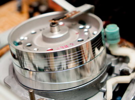
Added after 4 minutes 15 seconds:
_________________
“He who believes in his own luck is lucky” F. Goebbel.
_________________
“He who believes in his own luck is lucky” F. Goebbel.
_________________
“He who believes in his own luck is lucky” F. Goebbel.
_________________
Best regards, Alexander Safonov.
Good luck.
_________________
“He who believes in his own luck is lucky” F. Goebbel.
Keep in mind that a large outside light without a cover can light up the optical sensors of the cassette and, accordingly, the mechanics will not work correctly.Cover them (side) with pieces of electrical tape.
Clean the program switch, bend the contacts slightly for better grip.
_________________
Best regards, Alexander Safonov.
Good luck.
_________________
Best regards, Alexander Safonov.
Good luck.
_________________
Best regards, Alexander Safonov.
Good luck.
_________________
“He who believes in his own luck is lucky” F. Goebbel.
This software gear needs to be cleaned.
There usually several problems arise.
_________________
Best regards, Alexander Safonov.
Good luck.
When executing the command: "Unload" - the refueling stands are returned, and the extended loop of tape should be wound around the take-up spool. If this happens sometimes, then the adhesion of the central gear, transmitting rotation to the take-up unit, is likely. It is easy to check and more accurately find out the cause using "Diagnostic cassette", see page 2 of my branch "Collectors". The gear moves like a pendulum when reversed and should be freely (easily) thrown.
Last edited by Yarik on 27 Jun 2012, 20:17, edited 1 time in total.
_________________
“He who believes in his own luck is lucky” F. Goebbel.
_________________
“He who believes in his own luck is lucky” F. Goebbel.
_________________
About renovation: viewtopic.php? F = 3 & t = 93525 & st = 0 & sk = t & sd = a
I want needles for GZM and UNITRA.
I'm not a photographer 
_________________
“He who believes in his own luck is lucky” F. Goebbel.
_________________
“He who believes in his own luck is lucky” F. Goebbel.
Point 1 - turn the braking loop - if it is stretched or “slippery”, remove it, treat / wipe it with an ammonium solution and dry it with napkins immediately without allowing the glue to dissolve.
Point 2 - check the position of the tape tension lever stand in playback mode - the stand should be between the first stationary stand and the erasing head, if you look from above while in front of the front panel, then the tensioner stand should go to the left of the first stationary stand by 3-4 millimeters.
Check this position at the beginning, middle and end of the cassette - the position should not differ in all cases by more than 1 mm.
The tensioner lever itself has 3 positions for the spring, under normal conditions the tension should be in the range of 32-38 grams (if measured with a tentholometer, but this does not seem to threaten) Therefore, you can try two extreme positions for the spring and see the reaction.
Also check the fit of the erasing head - if it is on a plastic fastener, then sometimes due to cracks it can shift by changing the angle of inclination of the tape.
There were times when in every Russian family an honorable place in the living room was occupied not only by the TV, but also by the cassette video recorder.
There were times when in every self-respecting family an honorable place in the living room was occupied not only by the TV, but also by the VCR. They were especially appreciated for the fact that you can watch your favorite films and programs without commercial breaks, as well as arrange watching a family video.
Now everything has changed: there is a more powerful and "advanced" technology for watching movies at home - small compact DVD players, powerful home theaters ...
They are not so expensive, and their quality is good. But the paradox is that the good old VHS format is in no hurry to retire. Take a closer look at the windows of household appliances stores and you will see that not only many different models of VCRs are still sold there, but also a variety of videotapes with recordings of films, music, programs and cartoons.
And some experts of the multimedia market have exactly the information that the widespread distribution of the DVD format is a privilege, mainly, of residents of the capital. It is worth leaving outside Moscow and St. Petersburg, as you will see that the provinces still spend their leisure time watching videotapes. And rightly so, because VHS tapes have been the most common carrier of video information for quite a long time, and they are inexpensive.
So, if you have a large collection of videos on cassettes at home from the past, and the VCR has already "ordered to live a long time," do not rush to get rid of the film library: think, maybe it will still come in handy for you? If so, now is the time to consider buying a new VCR. Fortunately, today on the market you can find modern models for every taste.
When starting a purchase, first of all, you need to remember some information about these devices and decide what you really need - is it enough to buy a video player or do you still need a full-fledged video recorder?
Recall that the first type - a video player - is a cheaper and very simple type of video equipment that is needed exclusively for watching video tapes. Firstly, it lacks many additional functions - a built-in tuner (a special device for easy viewing and recording of TV programs), a clock or a timer. And the cheapest and simplest models do not even have the function of recording cassettes - only playback.
However, if you are sure that you will no longer need the TV recording function, then you can buy a non-recording player. But you won't be able to save a lot, because players with the recording function cost only a little more, but they already know how to record from one "video recorder" to another, as well as from a TV set.
Video players are an extremely simple technique. They have very simple controls, menus and remotes with only 5-7 buttons. Only two video heads are responsible for the recording and playback modes and there is no Long Play mode, in which twice as much information can be recorded on the same videotape.
The VCR is another matter. It is much more complicated, it costs more, but it can do much more than a player. If you buy this device, you can no longer worry about not being in time for the air of your favorite program: the tuner will allow you to record whatever you want without much hassle, and then arrange viewing at a time when it is convenient for you.
This very useful skill of VCRs has arisen because it does not need a TV for recording - it is enough to have access to a TV antenna. He does all other operations in automatic mode, which the owner programs for him in advance. Moreover, learning how to program a VCR is not a very difficult task. You just need to carefully read the instructions.
In addition, VCRs also have several additional video recording and playback modes: the same Long Play, as well as Super Long Play (or EP). With their help, you can make a better freeze frame, as well as find any desired fragment, rewinding the recording at different speeds.
Those amateurs who are fond of home video filming need a VCR in the household, since it allows you to edit the material on a cassette. Moreover, it would be better if this would be a device not with two video heads (it is very simple and will hardly provide the required quality), but with four, or even six.
Six-head models are the most expensive, but provide the best recording quality, because there are 4 heads for the image, and two more for the sound in stereo. And besides, they are often originally intended for editing work: there you can precisely join frames, insert fragments, find the last recorded fragment, or separately add sound to the footage.
With six heads, the owner of the tape recorder can enjoy all the benefits of stereo sound, even if the TV does not have this feature. After all, it provides a special output for external equipment, which means that you can connect a stereo system.
As an added bonus, some VCRs are equipped with input / output connectors not only on the back, but also on the front panel. This is especially convenient if you often have to "transfer" materials from a camcorder or from another VCR: there is no need to constantly climb up to the back of the device and grope for connectors.
Time Lapse VCR
Menu systems and remotes deserve special attention. The most ideal option if they are Russified. Moreover, the menu should be displayed on the TV screen, so that it is more convenient to select modes and program the Vidic without peering into the buttons, but quietly lying on the sofa. And even better, if the remote control is compatible with the TV and you can make it universal.
When choosing and buying a VCR, you should also pay attention to what color rendering systems it provides.Today, almost all devices support both the Secam system, in which Russian television broadcasts, and imported ones - American PAL and Japanese NTSC. But there are also annoying exceptions, so it's worth inquiring about this possibility of a VCR.
By the way: of all the three systems mentioned, NTSC is considered to be of the highest quality. And some professionals even specifically look for cassettes recorded in this standard on the shelves. But, unfortunately, we do not come across such records very often. Much more common is Secam or PAL, which camcorders are equipped with.
If the tape recorder, as expected, knows several systems, then it should automatically determine in which of them this or that recording was made, and switch to it. And you will not even think about manually selecting the playback mode, as it once was. And it is definitely more convenient.
Summing up, it can be noted that today it is quite easy to choose a VCR or a player. Thank God, today all these devices have a sufficient supply both in sound and picture quality, and in terms of service life (on average, today it is about 10 thousand hours of viewing). And since using this technique is simple and convenient, the choice comes down only to choosing a model to your liking.
Manufacturers from China and Korea, who are aware of the unquenchable popularity of VCRs, some time ago came up with a new marketing ploy and released the so-called "combines". Devices that combine a VCR and a DVD under one body. These devices, in essence, are very expensive and quite suitable in terms of quality basis for a home theater. Firstly, it saves space (which is very important in our small apartments), secondly, it uses one remote control, and thirdly, it saves the family budget.
Recorder digital video player
True, the playback quality and capabilities are slightly more modest than those of separately purchased equipment, but this is a nuance of all multifunctional devices. But the main drawback is not even this, but the fact that the combines have a MacroVision system, which does not allow rewriting video from DVD to cassettes. That is, you can only watch a cassette or DVD, but you will not be able to rewrite them into another format. Our craftsmen, of course, are looking for a solution to this problem, but so far to no avail.
| Video (click to play). |
So, rumors that VCRs are hopelessly outdated and not popular are greatly exaggerated. The industry is still developing, offering video lovers more and more new opportunities and models. So experts predict that videotapes will be watched in Russia for at least the next ten years. And it means that it is too early to write off "Vidiki" and throw it into landfills.


