In detail: do-it-yourself repair of the vom mtz 80 from a real master for the site my.housecope.com.
Jamming of the MTZ-80 power take-off shaft control lever and difficult control of the shift clutch leash to an independent or synchronous drive indicate a malfunction of the amplification mechanism (spring cup) and wear of the cam shift clutch. To determine the cause
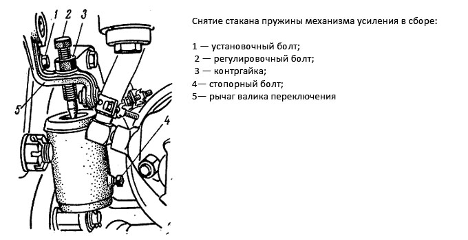
malfunctions of the amplification mechanism remove and disassemble the spring glass (Fig. 2.8.20).
Rice. 2.8.20. Removing the reinforcement spring cup assembly
1 - an installation bolt; 2 - an adjusting bolt; 3 - lock nut; 4 — locking bolt; 5 - lever of a roller of switching
When disassembling a glass with a compressed spring installed in it, care is taken and the operations are performed in a specific sequence.
First, the MTZ-80 power take-off shaft control lever is moved to a position at which the technological holes in the shift shaft lever 5 and the rear axle are aligned, and the adjusting bolt 1 is screwed into them.
Then release the locknut 3, screw the adjusting bolt 2 to failure into the lever 5 of the shift roller and the locking bolt 4 into the spring cup, then hold the glass with your hand and carefully unscrew the adjusting bolt 2.
After making sure of the reliability of fixing the glass to the body, remove the glass assembly. Clamp it under a press or in a clamp and unscrew the locking bolt 4. Defective parts are replaced. A press or clamp is also used for assembly.
In the event of a malfunction of the cam clutch, disconnect the gearbox from the rear axle and replace the worn out parts.
Continued rotation of the shaft end when the PTO is disengaged or its uneven rotation indicate a violation of the adjustment of the brake bands and their wear.
| Video (click to play). |
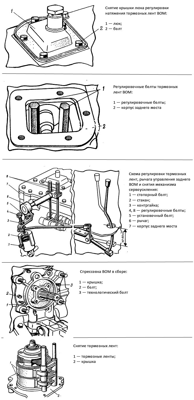
Adjustment of the tension of the brake bands and the PTO control lever is carried out as follows. Remove the hatch cover (Fig. 2.8.21) and tighten the adjusting bolts to failure (Fig. 2.8.22). Screw the adjusting bolt 5 (Fig. 2.8.23) into the lever 6 and the axle housing 7 and remove the servo amplification mechanism assembly.
Disconnect the rod from the power take-off shaft control lever, unscrew the bolts 8 until the PTO shank is free to rotate by hand force, connect the rod to the control lever, if necessary, rotate the plug to change its length and install the servo amplification mechanism.
If it is not possible to eliminate the malfunction, the PTO shaft is removed from the tractor. To do this, unscrew the rear cover mounting bolts and press out the PTO assembly with technological bolts (Fig. 2.8.24). Then remove the brake bands (Fig. 2.8.25) and measure their thickness. The belts are replaced with new ones with a thickness of less than 2.5 mm.
Rice. 2.8.21. Removing the hatch cover for adjusting the tension of the PTO MTZ-80 brake bands
Rice. 2.8.22. PTO shaft brake band adjusting bolts
1 - adjusting bolts; 2 - rear axle housing
Rice. 2.8.23. Adjustment diagram of brake bands, rear PTO control lever and removal of the servo assistance mechanism
1 - locking bolt; 2 - glass; 3 - lock nut; 4, 8 - adjusting bolts; 5 - an installation bolt; 6 - lever; 7 - rear axle body
Rice. 2.8.24. Pressing the MTZ-80 power take-off shaft assembly
1 - cover; 2 - bolt; 3 - technological bolt
Rice. 2.8.25. Removing brake bands
1 - brake bands; 2 - cover
The appearance of noise, increasing with an increase in the transmitted torque, and traces of grease on the rear cover indicate wear on the shaft splines, planetary gear parts, loss of elasticity or destruction of the oil seals.
In this case, the PTO is removed from the tractor. To check the technical condition, its back cover is clamped in a vice.Scrolling the shank, inspect the teeth of the gears and check the movement of the shaft shank in the bearings by hand.
Having found chips on the teeth, large displacements in the mates of individual parts or jamming of the shaft, the PTO is disassembled, defective parts are replaced (Fig. 2.8.26).
Rice. 2.8.26. Mutual arrangement of parts of the rear BOM MTZ-80
1 - plate; 2 - PTO cover; 3 - gasket; 4 - axes; 5 - rear PTO shaft; 6, 8, 15, 18 - bearings; 7 - brake bands with linings; 9 - bushing; 10 - drum; 11 - sun gear; 12 - carrier; 13 - satellite; 14 - satellite axis; 16 - rocker gear; 17 - glass; 19 - retaining rings; 20 - shaft; 21 - clutch; 22 - PTO casing
The carrier of the planetary gearbox is replaced (Fig. 2.8.27, 2.8.28) when the holes under the axis of the satellites are worn to a size of more than 20.2 mm, the surfaces for the brake band are worn down to a size of less than 158.0 mm.
Subject to replacement: the axles of the satellites (Fig. 2.8.29) when surfaces for needle bearings are worn down to a size of less than 19.92 mm; drum of inclusion (Fig. 2.8.30, 2.8.31) with wear of the surface under the brake band to a size of less than 159.0 mm and wear of the seat for the outer bearing race 209 to
sizes over 85.12 mm; the shaft of the planetary gearbox when the seats are worn down to a size of less than 39.96 mm for bearing 208, less than 49.97 mm for bearing 310, less than 44.96 mm for bearing 209.
When oil leaks from under the cuffs at the MTZ-80 PTO removed, inspect the gaskets between the rear axle and the cover. Replace damaged gaskets.
When oil leaks from under the shaft end, to replace the oil seals, unscrew the shank nut, remove the brake bands, press the carrier assembly with the bearing and the inclusion drum assembly, remove the retaining ring, press the shaft out of the cover, etc. The most important points of disassembly, assembly and adjustments of the rear axle and PTO are shown in fig. 2.8.32-2.8.44.
Rice. 2.8.27. Carrier pressing assembly
1 - carrier; 2 - PTO cover; 3 - puller
Rice. 2.8.28. Pressing on the carrier assembly
Rice. 2.8.29. Removal of satellites and satellite axles
1 - carrier; 2 - satellite; 3 - satellite axis
Rice. 2.8.30. Pressing the switching drum
1 - cover; 2 - drum; 3 - three-blade puller
Rice. 2.8.31. Pressing in the drum of inclusion
1 - cover; 2 - drum; 3 - puller
Rice. 2.8.32. Removing the MTZ-80 cam clutch
1 - cam clutch; 2 - leash; 3 - differential; 4 - rear axle body
Rice. 2.8.33. Removing the ring gear shaft bearing set screw
1 - set screw; 2 - shaft; 3 - rear axle body
Rice. 2.8.34. Removing the ring gear bearing circlip from the shaft
1 - retaining ring; 2 - bearing; 3 - ring gear
Rice. 2.8.35. Pressing the cup with the ring gear bearing from the shaft
1 - ring gear; 2 - drift
Rice. 2.8.36. Removing the ring gear bearing retaining ring from the glass
1 - retaining ring; 2 - bearing; 3 - glass
Rice. 2.8.37. Pressing the bearing into the glass
1 - bearing; 2 - glass; 3 - step adjustment
Rice. 2.8.38. Pressing the cup with the ring gear bearing onto the shaft
1 - ring gear; 2 - ring gear shaft; 3 - annular grip
Rice. 2.8.39. Installation of the ring gear shaft in the MTZ-80 rear axle housing
1 - holes for the set screw; 2 - rear axle body; 3 - ring gear
Rice. 2.8.40. Installing shims to adjust the differential bearings
1 - shims; 2 - bearing cup
Rice. 2.8.41. Checking the side play in the teeth of the main drive gears
1 - driven gear wheel of the main transfer; 2 - indicator
Rice. 2.8.42. Checking the axial clearance in the differential tapered bearings
1 - driven gear wheel of the main transfer; 2 - indicator
Rice. 2.8.43. Removing the circulating drum bearing retaining ring
1 - retaining ring; 2 - bearing; 3 - drum
Rice. 2.8.44. Pressing out the bearing from the drum
1 - bearing; 2 - drum; 3 - inertial puller
Jamming of the power take-off shaft control lever and difficult control of the drive of the shift clutch to an independent or synchronous drive indicate a malfunction of the amplification mechanism (spring cup) and wear of the cam clutch. To determine the cause of the amplification mechanism malfunction, remove and disassemble the spring cup (Fig. 2.8.20).
Rice. 2.8.20.Removing the reinforcement spring cup assembly:
1 - an installation bolt; 2 - an adjusting bolt; 3 - lock nut; 4 — locking bolt; 5 - lever of a roller of switching
When disassembling a glass with a compressed spring installed in it, care is taken and the operations are performed in a specific sequence. First, the PTO control lever is moved to the position at which the technological holes in the lever 5 of the shift shaft and the rear axle are aligned, and the adjusting bolt 1 is screwed in them. Then the locknut 3 is released, the adjusting bolt 2 is screwed all the way into the lever 5 of the shift shaft and the locking bolt 4 into the spring glass, then hold the glass with your hand and carefully unscrew the adjusting bolt 2. After making sure that the glass is securely fixed to the body, remove the glass assembly. Clamp it under a press or in a clamp and unscrew the locking bolt 4. Defective parts are replaced. A press or clamp is also used for assembly.
In the event of a malfunction of the cam clutch, disconnect the gearbox from the rear axle and replace the worn out parts.
Continued rotation of the shaft end when the PTO is disengaged or its uneven rotation indicate a violation of the adjustment of the brake bands and their wear.
Adjustment of the tension of the brake bands and the PTO control lever is carried out as follows. Remove the hatch cover (Fig. 2.8.21) and tighten the adjusting bolts to failure (Fig. 2.8.22). Screw the adjusting bolt 5 (Fig. 2.8.23) into the lever 6 and the axle housing 7 and remove the servo amplification mechanism assembly. Disconnect the rod from the PTO control lever, unscrew the bolts 8 until the PTO shank is free to rotate by hand force, connect the rod to the control lever, if necessary, rotate the fork to change its length and install the servo amplification mechanism.
If it is not possible to eliminate the malfunction, the PTO shaft is removed from the tractor. To do this, unscrew the rear cover mounting bolts and press out the PTO assembly with technological bolts (Fig. 2.8.24). Then remove the brake bands (Fig. 2.8.25) and measure their thickness. The belts are replaced with new ones with a thickness of less than 2.5 mm.
Rice. 2.8.21. Removing the hatch cover for adjusting the tension of the PTO brake bands:
1 - hatch;
2 - bolt
In today's article, we will consider in detail such a mechanism as the power take-off shaft of the Belarus MTZ-82 and MTZ-80 tractor, its scheme and principle of operation, as well as provide complete instructions for its disassembly and basic repair. Why two models at once, you probably ask? - because their design is absolutely identical.
The main purpose of this mechanism is to drive active machines that are aggregated with a tractor. At the location, the rear and side PTOs are distinguished. In the MTZ 80 and MTZ 82 models, a combined power take-off shaft is used, so it can have both a dependent (or synchronous) and an independent drive.
If the drive is not synchronous, then it communicates with the flywheel of the engine itself, this will provide the required rotational speed of the shaft itself, no matter how fast the tractor moves, and whether the clutch is engaged or not. Also, the drive itself can have the following speeds (540 and 1000 rpm) at a crankshaft speed of 2100 rpm.
As for the dependent drive, it is connected with the leading gear wheel of the 2nd stage of the mechanical gearbox of the gearbox, therefore, in this case, the frequency will depend and will be 3.5 revolutions per meter of travel.
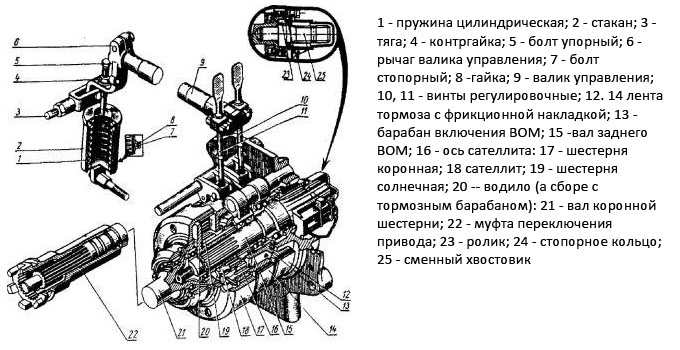
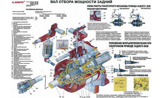
Below is a diagram of the rear power take-off shaft drive for tractors of the MTZ 80 and 82 models, and we will give its explanation.
The main mechanisms of the rear PTO include: a 2-stage gearbox, a drive type switch, a mechanical gearbox, a dependent or independent type switch.
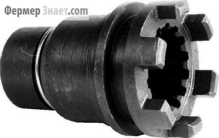
The rotational speed of the independent power take-off shaft is switched by means of a clutch (5), which is installed on the shaft spline (6). And the mechanism that is responsible for this is a hexagon, it is located in the bottom cover of the one-piece clutch housing.
The drive is set by switching the cam shaft clutch (11) using the lever (18), it is located on the cab floor.
Lever (18) has 3 positions: clockwise rotation - dependent type, anti-rotation - independent, middle position - neutral. Remember, the non-synchronous type must be turned on only when the engine is not running or the very minimum crankshaft speed, but the synchronous type only when the tractor is stopped.
This mechanism is one of the important components, therefore, we will dwell on its design in more detail.
this mechanism is designed to control the power take-off shaft and has a gear ratio of 1.47. Its components are: a driving crown (17), satellites (18), a sun gear (19). The satellites are installed on the axles (16), which are pressed into the carrier bore.
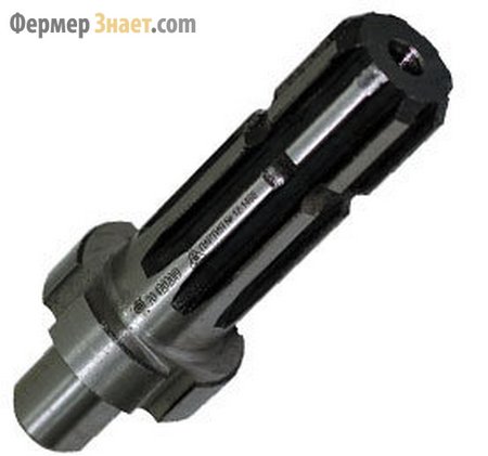
By special order, the plant can manufacture the shaft (15) as composite, i.e. into its rear end, you can insert special shanks (25) with 8 (for 540 rpm) or 21 (for 1000 rpm) splines, for various tools.
The planetary gearbox itself controls two band-type brakes.
As you can see, the diagram is quite simple to understand.
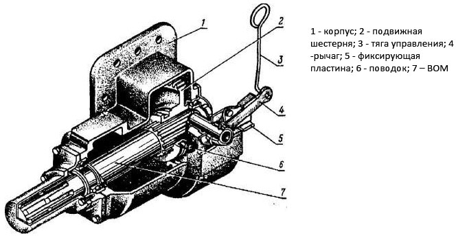
Below is a diagram of the side PTO shaft for these tractor models.
In this case, it is still easier, through the movable gear wheel (2), the drive is carried out, while the gear itself moves along the splines with the help of the driver (6). The side shaft can only be engaged with the clutch disengaged using pull rod 3.
One of the main problems is a sticking of the shaft control lever or difficult control of the clutch driver. Most likely - this is a malfunction of the amplification mechanism (spring cup) and wear of the cam clutch. To accurately determine the breakdown, it is necessary to remove and disassemble it.
At the time of disassembly, care must be taken and performed strictly in a specific sequence. First, it is necessary to move the power take-off shaft control lever to the position when the technological holes in the lever of the shift shaft (5) and the rear axle are displaced. Then the locknut (3) must be loosened and the adjusting bolt (2) must be screwed into the roller switch lever until it stops, and the locking bolt (4) into the glass.
After making sure of good fixation, remove the glass assembly. Then we clamp it under a press and unscrew the bolt (4). We change all faulty mechanisms.
If the cam clutch is faulty, then it is necessary to disconnect the gearbox from the rear axle and replace the parts.
We adjust the tension of the bands and the lever according to the diagram below.
If there is an oil leak from under the shank, then for replacement it is necessary to unscrew the cuff, remove the brake band, compress the carrier and remove the retaining ring. The most important points of disassembly are shown in the figure below.
What are the main symptoms of a malfunctioning PTO shaft? For example, you have started to jam the power take-off shaft control lever, heavy, problematic control of the shift clutch leash to an independent or synchronous drive. Most likely, the amplification mechanism (spring cup) is faulty and the cam clutch has worn out, to put it simply, worn out. To find out finally what happened, the reinforcement mechanism is dismantled and the spring glass is disassembled as in Fig. 2.8.20.
Disassembly of the glass is carried out with extreme care and in a certain sequence. First, the power take-off shaft control lever (hereinafter referred to as PTO) is set to the position when the technological holes in the lever 5 of the shift shaft and the rear axle are aligned, and then the adjusting bolt number 1 is screwed into them. At the next step, the lock nut 3 is loosened. , screw the adjusting bolt 2 until it stops into the lever 5 of the shift shaft and the locking bolt 4 into the spring cup. Then, gently holding the glass with your hand, smoothly unscrew the adjusting bolt 2. It is very important to make sure that the glass with the body is clearly fixed. Only after that do they remove the glass assembly. Then squeeze with a clamp and unscrew the locking bolt 4.All that needs to be replaced is replaced. For reassembly, a clamp or, if available, a press is also used.
Rice. 2.8.20. How to remove the spring glass of the reinforcement mechanism assembly of the MTZ tractor:
1 - an installation bolt; 2 - an adjusting bolt; 3 - lock nut; 4 - locking bolt; 5 - shift roller lever
If it is determined that the cam clutch is out of order, disconnect the gearbox from the rear axle, and then change the worn out parts.
If, when the PTO is disengaged, the shaft end is still spinning, the brake bands are incorrectly adjusted or they are worn out.
How to adjust the tension of the brake bands and the PTO control lever? This work is done as follows. First, remove the hatch cover (Fig. 2.8.21) and screw the adjusting bolts all the way (Fig. 2.8.22). Then screw the adjusting bolt 5 (Fig. 2.8.23) into the lever 6 and the axle housing 7 and separate the servo-assisted mechanism assembly. The next procedure is to separate the thrust from the PTO control lever. We unscrew the bolts 8 to the point where the PTO shank can be easily turned by hand effort. Then again connect the rod with the control lever and, if necessary, turn the fork to adjust its length and install the servo amplification mechanism.
Even if after all these works it was not possible to fix it, the PTO is removed from the tractor. For this purpose, unscrew the tightening bolts of the rear cover and press out the PTO as a whole with technological bolts (Fig. 2.8.24). After that, the brake bands are thrown off (Fig. 2.8.25) and their thickness is measured. The belts are replaced with serviceable belts with a thickness of less than 2.5 mm.
Rice. 2.8.21. Removing the hatch cover for adjusting the tension of the PTO brake bands of the MTZ tractor:
1 - hatch;
2 - bolt
Rice. 2.8.22. Adjusting bolts of the PTO brake bands of the MTZ tractor:
1 - adjusting bolts;
2 - rear axle body
Rice. 2.8.23. Adjustment diagram of brake bands, rear PTO control lever and removal of the servo amplification mechanism of the MTZ tractor:
1 - locking bolt;
2 - glass;
3 - lock nut;
4, 8 - adjusting bolts;
5 - an installation bolt;
6 - lever;
7 - rear axle body
Rice. 2.8.24. Pressing BOM assembled MTZ tractor:
1 - cover;
2 - bolt;
3 - technological bolt
Rice. 2.8.25. Removing the brake bands of the MTZ tractor:
1 - brake bands;
2 - cover
If you paid attention to the hum, which increases with an increase in the transmitted torque and there are smudges from grease on the back cover, this is evidence that the shaft splines have worn off, the parts of the planetary gear are worn out, and the cuffs either torn or lost their elasticity.
In this state of affairs, the PTO is removed from the tractor. To examine it, the back cover is clamped in a vice. Turning the shank, pay attention to the gear teeth and use your hand to diagnose the movement of the shaft shank in the bearings. If it turned out that there are chips on the teeth, the displacements in the mates of individual parts are large enough, there is a jamming of the shaft - the PTO must be sorted out with the replacement of faulty parts (Fig. 2.8.26).
Rice. 2.8.26. Mutual arrangement of parts of the rear BOM of the MTZ tractor:
1 - plate; 2 - PTO cover; 3 - gasket; 4 - axes; 5 - rear PTO shaft; 6, 8, 15, 18 - bearings; 7 - brake bands with linings; 9 - bushing; 10 - drum; 11 - sun gear; 12 - carrier; 13 - satellite; 14 - satellite axis; 16 - rocker gear; 17 - glass; 19 - retaining rings; 20 - shaft; 21 - clutch; 22 - PTO casing
The carrier of the planetary gearbox (Fig. 2.8.27, 2.8.28) must be changed in the following cases: when grinding the holes under the axis of the satellites more than 20.2 mm; the development of surfaces for the brake band to a size of less than 158.0 mm.
The axes of the satellites (Fig. 2.8.29) must be changed when the surfaces for needle bearings are abraded to a size of less than 19.92 mm; the drum of inclusion (Fig. 2.8.30, 2.8.31) must be changed when the surface under the brake band is abraded to a size of less than 159.0 mm and the seat for the outer bearing race 209 is more than 85.12 mm; the shaft of the planetary gearbox must be changed if the steel seats are less than 39.96 mm for bearing 208, less than 49.97 mm for bearing 310, less than 44.96 mm for bearing 209.
If oil leakage is found in the area of the cuffs at the removed PTO shaft, inspect the gasket between the rear axle and the cover. Inappropriate gaskets are changed.
What if oil seeps out from under the shaft end? The cuffs need to be replaced. First, unscrew the shank nut, remove the brake bands. Then the carrier assembly with the bearing and the drum of inclusion assembly are pressed together. Next, remove the retaining ring, press out the shaft from the cover. The most important moments of reassembly and adjustment of the rear axle and PTO are shown in Fig. 2.8.32-2.8.44.
Rice. 2.8.27. How to compress the carrier assembly of the MTZ tractor:
1 - carrier;
2 - PTO cover;
3 - puller
Rice. 2.8.28. How to press in the carrier assembly of the MTZ tractor:
1 - carrier;
2 - puller
Rice. 2.8.29. Removing the satellites and satellites of the MTZ tractor:
1 - carrier;
2 - satellite;
3 - satellite axis
Rice, 2.8.30. Pressing the drum of turning on the MTZ tractor:
1 - cover;
2 - drum;
3 - three-blade puller
Rice. 2.8.31. Pressing in the drum of turning on the MTZ tractor:
1 - cover;
2 - drum;
3 - puller
Rice. 2.8.32. Removing the MTZ tractor cam clutch:
1 - cam clutch;
2 - leash;
3 - differential;
4 - rear axle body
Rice. 2.8.33. Unscrewing the set screw of the bearing of the ring gear shaft of the MTZ tractor:
1 - set screw;
2 - shaft;
3 - rear axle body
Rice. 2.8.34. Removing the ring gear bearing retaining ring from the MTZ tractor shaft:
1 - retaining ring;
2 - bearing;
3 - ring gear
Rice. 2.8.35. Pressing the cup with the ring gear bearing from the MTZ tractor shaft:
1 - ring gear;
2 - drift
Rice. 2.8.36. Removing the ring gear bearing retaining ring from the MTZ tractor glass:
1 - retaining ring;
2 - bearing;
3 - glass
Rice. 2.8.37. Pressing the bearing into the glass of the MTZ tractor:
1 - bearing;
2 - glass;
3 - step adjustment
Rice. 2.8.38. Pressing a glass with a ring gear bearing onto the MTZ tractor shaft:
1 - ring gear;
2 - ring gear shaft;
3 - annular grip
Rice. 2.8.39. Installation of the ring gear shaft in the rear axle housing of the MTZ tractor:
1 - holes for the set screw;
2 - rear axle body;
3 - ring gear
Rice. 2.8.40. Installation of shims for adjusting the differential bearings of the MTZ tractor:
1 - shims;
2 - bearing cup
Rice. 2.8.41. Checking the lateral clearance in the teeth of the main gears of the MTZ tractor:
1 - driven gear wheel of the main transfer;
2 - indicator
Rice. 2.8.42. Checking the axial clearance in the tapered bearings of the MTZ tractor differential:
1 - driven gear wheel of the main transfer;
2 - indicator
Rice. 2.8.43. Removing the retaining ring of the MTZ tractor engaging drum bearing:
1 - retaining ring;
2 - bearing;
3 - drum
Rice. 2.8.44. Pressing out the bearing from the drum of turning on the MTZ tractor:
1 - bearing;
2 - drum;
3 - inertial puller
Adjusting the PTO MTZ 80 is a mandatory and regular procedure. The PTO scheme provides the attachment with the necessary force, which is transmitted directly from the power plant. Basically, it is a combined device that needs regular maintenance. Otherwise, the tractor loses its functionality and is sent for repair.
In this article, we will consider which PTO is installed on the MTZ-80 tractor, the principle of its operation, adjustment, repair and possible problems. By the way, the MTZ-82 tractor is equipped with exactly the same device. Therefore, the scheme of PTO maintenance and repair for these two machines is identical.
The abbreviation PTO stands for the power take-off shaft, which is installed on the MTZ-80 tractor or an MTZ-82 similar to it, to ensure the drive of mounted systems and units.
According to the installation method, PTO can be of lateral or rear type. The most optimal are the rear power take-off shafts. They are installed on most wheeled vehicles and on the MTZ-80 tractor in particular. According to the principle of operation of the PTO of the MTZ-82 tractor, there can be three types:
- Synchronous. In other words, such a shaft is called dependent. The unit turns directly depend on the mode of movement of the equipment. The power take-off shaft is driven directly from the gearbox gearbox. The average rotational speed is 3.5 revolutions / 1 meter of track.
- Independent. Such a mechanism is connected directly to the MTZ-82 engine.Its rotation frequency depends on the engine flywheel with which the tractor is equipped. In addition, the clutch engaged or disengaged plays a role. For MTZ-80, the shaft rotation speed is 540 or 1000 rpm.
- Combined. Such a PTO can operate in the two modes listed above.
In order for the power take-off shaft, which is installed on the tractor, to function normally, it must be periodically inspected and adjusted. This applies not only to MTZ-82, but in general to all tractors. The adjustment scheme looks like this:
- The eccentric axis is set to its original position. The inflicted risk should be on the right and vertical. The position is fixed by means of locking plates.
- The traction is disconnected.
- The bolts of the glass are unscrewed in order to release the springs.
- The cover of the rear axle hatch is dismantled. This provides access to the head of the tensioning screw.
- The lever is placed in neutral and secured with a bolt. Then the locking plate is removed and the screw is tightened until it stops. After that, the bolt of the locking lever can be removed.
- The stop bolt is screwed into the outer sleeve.
- The lever is moved to the "on" position. Traction is installed.
- By adjusting the traction, the required lever play is set.
- Upon completion of the adjustment, all parts are returned to their places, the rods and fastening bolts are reinforced with locknuts.
The PTO installed on the MTZ-82 tractor may not work correctly for the following reasons:
Visual inspection revealed cracks in the lugs and control roller. The glass with springs has deep dents.
The MTZ-80 tractor is definitely being repaired, the troubleshooting diagram looks like this:
- align the holes of the shift roller and the rear axle. This can be done using the control lever. When the holes match, a set bolt is screwed into them;
- the lock nut of the adjusting bolt is loosened, which, in turn, is screwed all the way into the lever of the switch roller;
- the locking bolt is screwed into the glass. Then carefully remove the adjustment bolt;
- thus, the entire glass with springs is removed. Then it is disassembled and worn or damaged parts are replaced.
In this case, the MTZ-82 tractor cab is dismantled and the gearbox is disconnected from the rear axle. After this, the coupling is replaced. Repair of this part is impractical.
The power take-off shaft installed on the MTZ-80 tractor works in jerks. Most likely, the spline joints have become unusable or the teeth of the central gear have ground off. The work scheme looks like this:
First you need to dismantle the PTO. The shaft is pressed out and the condition of the gear is assessed. For this, the rear axle and the cam clutch are disconnected. If large gaps are visually observed or the gear moves freely, the power take-off must be sent in for repair. After replacement, the shaft is reinstalled and adjusted.
This means that the locking nut is loose. As in the previous case, the unit is completely dismantled from the MTZ-82 tractor. If possible, the thread is restored, and the nut is tightened all the way. If not, you will have to disassemble the entire structure and carry out more time-consuming repairs.
This indicates wear on the cuff or pad. In this case, the shaft is dismantled and the gasket between the PTO cover and the rear axle is replaced. If the leakage comes from the shank side, the stopper ring is removed, the shaft is pressed out and the oil seals are replaced.
The likely cause is band brakes. They need adjustment or complete replacement. If the adjustment fails to solve the problem, it is necessary to remove the PTO from the tractor and measure the thickness of the brake bands. If the thickness is less than 2.5 millimeters, the tapes are replaced.
This indicates wear on the satellite axles, support bearings or spline joints.The technical condition of these units can be assessed only after the PTO is removed from the tractor. After that, the teeth are inspected and the clearances are checked. If repair is possible, the parts are restored, if not, then they are replaced.
If the creeper gearbox has been dismantled or disassembled, you will need to check or adjust the PTO. To do this, the tractor is put on a jack (under the driving wheels) and the selection shaft is turned, with alternating gears.
When performing this operation, the PTO of the tractor must be transferred to the synchronous mode. When scrolling, the cogwheels of the gears should rotate freely.
PTO MTZ is a vehicle assembly that transmits a rotational impulse from the power unit to additional equipment and other systems. The MTZ-82 power take-off shaft is located at the rear of the vehicle body.
The diagram of this system of the tractor device includes:
- a supporting disc of the coupling mechanism;
- gear parts of the leading type;
- side semi-independent selection shaft and two-speed independent shaft;
- gear elements and driven shaft;
- toothed clutch;
- intermediate and secondary shaft;
- gear drive parts and locking bolt;
- drove;
- stopping brake mechanism.
PTO MTZ-82 - diagram and drawing can be found in the user manual.
The main mechanism is a rear-type gearbox with 2 stages and a shift mechanism of dependent and independent form.
The rotational speed is carried out using a clutch, which is located on the spline on the machine. The device responsible for the mechanical control of the PTO shaft is a hexagonal element located on the rear cover of the clutch housing.
Switching the cam mechanism sets the drive: the lever is moved forward, and the operation of the entire system begins, when the handle is moved to the "Off" position, the system stops working.
The lever can be in 3 positions: if you turn it clockwise, the dependent type is set; if you turn the handle counterclockwise, the device will go into an independent type; the middle position is synchronous operation (before setting this position, the motor must be switched off).
Adjustment of PTO MTZ (power take-off shaft):
- Place the vehicle on a special viewing platform.
- Set the axis of the central disk of the main system to its original position.
- The inflicted risk should be located on the right side in an upright position, i.e. the "AND" mark will be on the right.
- Secure at risk with locking plates and screws.
- Disconnect the rod.
- Unscrew the bowl screws to release the spring mechanism.
- Remove the rear axle drive hatch cover to gain access to the tension bolt head.
- Place the clutch handle in neutral mode and fix it with the M10 * 60 locking bolt. It is screwed into a hole in the lever, which should be on the back of the drive axle housing. After that, the locking plate is removed; it can be removed by dismantling the locking handle.
- Screw the stop bolt into the outer sleeve to the “A” mark (27-31 mm deep).
- Move the handle to the "On" position.
- Reinstall the traction mechanism. Then adjust the handle backlash by setting the required swinging zone of the handle to the middle hole of the control panel slot.
- Check the speed rotation at the rear PTO shift speed.
After checking, the shaft is installed back on the MTZ-82 tractor.
Additionally, it may be necessary to adjust the band brake in cases where:
- the shaft starts to tow;
- the handle rests against the slot during switching;
- to activate the PTO, an effort of more than 16 KGS is required;
- there is unstable fixation in extreme positions;
- PTO turns on unevenly (it does not work, then it works).
Band Brake Adjustment Procedure:
- Set the handle to synchronous mode.Fix the position of the handle.
- Unscrew the nut and remove the plate from the groove of the shanks.
- Using an open-end wrench, turn the axle mechanism clockwise until the gap between the gearbox and PTO is selected.
- Set the plate to its original position and tighten all the nuts in place.
- Remove the locking bolt from the handle.
- Carry out adjustment.
- Turn the axle counterclockwise.
- Assemble the mechanism in reverse order.
If, after performing work on adjusting the brake mechanism, the axle has shifted to the left side of the vehicle body, this means that the power unit has used up the corrective stock.
In this case, you need to turn the eccentric counterclockwise, returning it to its original position. After that, the shaft is re-adjusted.
Possible breakdowns, repairs and malfunctions:
- Jammed shaft handle on machines: engaging requires a lot of effort from the driver. In this case, it is recommended to inspect the spring cup or cam-type clutch for damage and wear.
- Increasing extraneous noise during an increase in torque values. Such a malfunction may be associated with wear of the PTO splines and elements of the planetary-type gear mechanism. It is also worth inspecting the cuffs for elasticity and damage.
- The shaft is unstable, jerky. The breakage can be associated with the spline joints of the mechanism. Or the gear moves too freely on the base because her teeth were worn out. Disconnect the rear axle from the cam clutch. Make an inspection for the width of the gaps. If the clearance is too large, it is recommended to replace the shaft.
- The engine is not running at full power. The band brakes should be replaced and adjusted.
- The tail of the shaft moves too freely. In this case, it is recommended to tighten the loosened nuts. Replacement of threads may be required.
Traces of grease on the shaft cover may indicate worn oil seals or gear gaskets. It is necessary to remove the PTO and replace the damaged system components.
You can ask questions only after registration. Login or register, please.
Good evening, help me figure out the wom's slipping. The ribbons are new adjustment according to the book and, it, slips especially when working with a button. Thanks in advance.
tighten the outer screw by 1-2 turns in the off position. if the drum is brought up, then it is possible that the screw rests on the drum and the tape does not jam - in this case, cut off 1 cm of thread on the adjusting screw.
Yes, the drums are very old and so that the bolts did not touch the drums before screwing them, I put them on their unthreaded nuts. Maybe you need to replace the snare drum? or something else?
Good day, put on new tapes and a new snare drum is better but not great. What else to see.
I have the same problem (the Engineer carries hooded belts. The basement consumer goods cooperative. The linings come off. The bushings come off. Enough for a day and a half (You have to carry KIS-10) But it's cheap.
If only the engineer themselves and the nuts twisted and such bibs were dragged back and forth, maybe they would then have realized that only cheese in a mousetrap is cheap
HOW to remove the PTO and how to adjust it after installation?
HOW to remove the PTO and how to adjust it after installation?
In general, I had a thing with a vom, I could stop it with my hand, inside the vom itself there is a gear with internal teeth, they were completely licked off
| Video (click to play). |
Hello everyone, I work at MTZ with a heavy tiller. The first season did not tighten the tapes a lot and everything worked fine. but the tape ended had to be replaced. put on the advice of experienced tractor drivers a tape - the braid shaft is slipping stopped pulling the cutter there was some whistle new tractor advise what to do and how to do it

