In detail: do-it-yourself repair vyatka machine from a real master for the site my.housecope.com.
The main advantage of the machine is full automation of washing modes, including pre and main wash, rinsing, special treatment and spinning of the laundry. With a fairly simple (without electronic elements) and reliable electrical circuit, the machine performs all operations without the help of a person. This is achieved by using a command device in this design, which contains a program of 36 cycles. The washing rhythm is set by the MT electric motor, which is mechanically connected to the drum of the command device (Fig. 1).
Rice. one Schematic diagram of a household washing machine "Vyatka-avtomat-12-01"
In order to better understand the principle of operation of the electrical circuit and to simplify the search for possible malfunctions, its description is provided. A description of the operation of the electrical circuit of the machine is given for the first program of the "Vyatka-automat-12-01" model.
To set the required program, turn the control knob clockwise, aligning the program number with the pointer marked on the front panel.
The machine is started by pulling the program setting knob towards itself until it clicks, at the same time contacts 13-T, 14-T of the command device are closed and the indicator lamp lights up. Sequential processing of the cycles begins.
The cyclogram in the form of a table can be viewed in Fig. 2, or from another source in Fig. 3, and its description is given below.
Rice. 2 Cyclogram Vyatka-automatic machine
Rice. 3 Cyclogram Vyatka-automatic machine
Cycle 2. At the initial moment of the cycle, the contacts of the controller 8-T, 5-T, 4-T open, and the contacts 7-B, 4-B close, while the power supply circuit of the electric heater R is closed through contacts 7-B, and the water heating begins. Opening the contact 8-T stops the voltage supply to the electric motors of the drives of the command device and the drum MT and ML. After the water in the tank warms up to + 40C, the TN-1 temperature sensor-relay is triggered, voltage is supplied to the ML and MT electric motors through its closed contacts. The commander and drum drives begin to work. The drum rotates in a soft rhythm (7 seconds - movement, 48 seconds - pause, 7 seconds - movement, 13 seconds - pause, then the sequence is repeated). The duration of the cycle, excluding the time required for heating the water, is 2.5 minutes.
| Video (click to play). |
Cycle 3. Contact 4-T closes, and within 5 minutes. the wash is carried out with an intensive rhythm, while the water heating continues.
Cycle 4. Water heating continues. Contact 4-B closes, and within 5 minutes. the drum rotates with a gentle wash cycle.
Cycle 5. The prewash ends and the water starts draining. This is done by closing terminal 6-T on the MPS pump motor power supply circuit. At the same time, contact 7-B opens, turning off the power of the pre-heater R. During the entire cycle, equal to 2.5 minutes, the drum rotates with a soft wash mode.
Cycle 6. The main wash starts from the sixth cycle. At the same time, through contacts 11-V and 12-T, voltage is applied to the coils of the solenoid valves EV3 and EV4, filling the tank with cold and hot water begins. When the water in the tank reaches the lower level, contacts 1-2 of relay P close, the water supply to the tank is stopped, the MT, ML electric motors are turned on. Within 2.5 minutes. the drum rotates with an intense rhythm.
Cycle 7. Contact 8-T opens, the electric motors of the drum drives and the command device are de-energized, and they stop.Through the closed contacts 7-V and 10-V, voltage is applied to the heater R, water heating begins and continues until the temperature rises to + 40C. In this case, the TN-1 sensor-relay is triggered and through its closed contacts voltage is supplied to the electric motors of the drum drives and the command device. The drum begins to rotate with a soft rhythm and continues for 5 minutes.
Cycle 8, 9 The drum continues to rotate with a soft rhythm for 10 minutes. Water heating continues.
Cycles 10, 11, 12. Contact 4-T closes, and the drum begins to rotate with an intense rhythm. The duration of three cycles is 15 minutes. Water heating will continue until the end of cycle 21; if the water temperature reaches + 90C earlier, then the contacts ТН-2 and ТН-3 will work and the heating will stop.
Cycle 13 The rotation of the drum, due to the closure of the 4-B contact, goes into a soft wash mode.
Cycles 14, 15, 16. Contact 4-B opens, 4-T closes, drum rotation continues in an intense rhythm for 15 minutes.
Cycles 17, 18, 19. The rotation of the drum switches to a gentle wash cycle, the cycle time is 15 minutes.
Cycles 20, 21. Continuation of the drum rotation with an intense rhythm for 10 minutes.
Cycle 22. Contacts 7-V and 10-V open, disconnecting the supply voltage of the heater R and thereby stopping the heating of the water. Through the closed contacts 2-B, 1E, 5-T and 11-B, the EV3 solenoid valve is activated, which provides two additional fills with cold water. The cycle time is 2.5 minutes.
Cycle 23. The operations listed during the 5th cycle are performed. The main wash has ended.
Cycle 24. Voltage is supplied to electric motors MT and ML through contacts 8-Т and 4-Т, reversing contact 1, contacts 9-Т, 3-Т. The drum rotates with an intense rhythm for 5 minutes. Water filling begins through the open EV3 valve, which is powered through closed contacts 1-3 of the P and 11-B level relays of the controller.
Cycle 25. Same as cycle 5 and 23. End of the first rinse.
Cycle 26. Water is injected through the open EV3 valve. After the P level switch is triggered, the electric motors of the drum drive and the command device begin to rotate. The drum rotates with an intense rhythm for 2.5 minutes. During this period of time, when contact 2-B is closed, an additional water fill occurs.
Cycle 27. Contact 6-T closes, the MPS pump turns on, the water is drained simultaneously with the rotation of the drum in an intensive rhythm. The cycle time is 2.5 minutes. End of the second rinse.
Cycle 28. During the transition from cycle 27 to cycle 28, the drum slowly rotates counterclockwise. At the beginning of the 28th cycle, the drum is turned on in the centrifuge mode, and the laundry is pre-wrung out. The voltage through contacts 1-3 of the level relay P, 5-V, 9-V, 3-V of the command device, capacitors C1 and C2 connected in parallel, is supplied to the MC-2 terminal of the electric motor. At the same time, voltage is supplied to the MPS pump motor through contacts 10-Т, 8-Т, 6-Т. The cycle time is 2.5 minutes.
Cycle 29. It is similar to the 26th cycle, but the washing rhythm is soft (contact 4-B is closed).
Cycle 33 - similar to 26, but filling is done through the EV2 valve, since contact 11-Т closes. A means for special treatment of linen is introduced into the tank together with water.
Cycle 35 - similar to 28, but the spin duration is increased to 5 minutes.
Cycle 36 - contacts 13-T and 14-T of the controller open, the supply voltage is removed from the circuit. The program has been completed.
As noted earlier, the main element of the electrical circuit, its "brain center" is the command apparatus. This device consists of an electric drive, contact groups and a drum on which the program is applied. When the electric motor of the commander drive is turned on, its drum begins to rotate, closing (opening) at certain intervals one or another group of contacts, which in turn turns on (turns off) the machine unit, which is necessary at the moment to comply with the washing technology. The sequence of closing the contacts of the controller, which must be observed when determining the cause that caused the malfunction of the first and essentially the entire program, is described above.
To find the cause of the failure of the machine, it is necessary to analyze its operation.The first thing to figure out is at what cycle and what exactly does not work. Further, based on the description of the schematic diagram, it is necessary to determine which circuit (contact) currently includes the supply voltage of the idle unit. Then the element-by-element check of this circuit is started. It is most convenient to start with testing the unit itself, gradually narrowing the search circle to identify a faulty contact or circuit section.
Finding a circuit malfunction is much more difficult than fixing it. To do this, it is necessary either to replace the failed elements, or, if this is not possible, to repair them. Therefore, it does not describe how to replace or repair defective items. Below are the external signs of possible malfunctions and the circuits to be checked in accordance with its sequence. At the same time, when determining the serviceability of a contact or unit with a probe, it is necessary at the time of verification to disconnect all wires going to the circuit from one of its terminals. This is due to the fact that the circuit of the tested contact may be closed through other nodes of the circuit, which will lead to serious miscalculations in identifying an invalid element.
Greetings to all members of the forum!
The topic is this, I rented an apartment in it there is a Vyatka washing machine - an automatic machine.
It needs to be repaired, because it does not even connect to the mains and the door for loading linen is locked.
If someone has encountered this problem, please write where it is possible to repair it or tell me who can come and the cost of this event (house call).
Thanks in advance.
09.02.09 16:52 Reply to the message Vyatka needs to be repaired! user yad
Why can't a person find the videos they want on Youtube? The thing is that a person cannot come up with something new and look for it. He was out of fantasy. He has already watched a lot of various channels, and he no longer wants to watch anything (from what he watched earlier), but what to do in this situation?
In order to find a Youtube video that suits your needs, it is imperative to keep searching. The harder your search is, the better your search result will be.
Remember that you only need to find a few channels (interesting), and you can watch them for a whole week or even a month. Therefore, in the absence of imagination and unwillingness to search, you can ask your friends and acquaintances what they are looking at on Youtube. Perhaps they will suggest original vloggers that they like. You, too, may like them, and you will become their subscriber!
Online mp3 cutting is convenient
and a simple service to help you
create a musical ringtone yourself.
YouTube video converter Our online video
the converter allows you to download videos from
YouTube website in webm, mp4, 3gpp, flv, mp3 formats.
These are radio stations to choose from by country, style
and quality. Radio stations all over the world
over 1000 popular radio stations.
Live broadcast from webcams is made
absolutely free in real
time - broadcast online.
Our Online Television is more than 300 popular
TV channels to choose from, by country
and genres. Broadcasting of TV channels is free.
A great opportunity to start a new relationship
with a continuation in real life. Random video
chat (chat roulette), the audience is people from all over the world.
One of the most common reasons leading to the failure of the Vyatka-Avtomat washing machine is the failure of the electric motor (EM) winding in the command device drive. In repair shops, such a malfunction is usually eliminated by replacement. Moreover, they prefer to deal not with the renewal of a burnt out cheap winding and not even with a "mocking" electric motor, but with an expensive command apparatus (KA), which includes all this as a "monolith" that cannot be disassembled.
A complex unit is replaced entirely, no one cares about the client's financial expenses.It is not surprising that the owner of a deteriorated washing machine seeks to repair it on his own, regardless of time or lack of experience.
But L1, which only needs to be rewound, is nothing more than a coil (Fig. 1a) of a multi-pole electromagnet, mounted on an axis and which is the rotor of an electric motor. You should also consider other factors that complicate the repair. In particular, there is a gear at the end of the rotor. Of course, the ED also has a stator - a kind, stamped one. The electric motor is attached to the controller (Fig. 16) with three pins entering the holes in the spacecraft body and slightly flared from the rear side.
When disassembling this unit, make sure that the current-carrying conductors are not disconnected from the terminals. This precaution is dictated not only and not so much by the hassle of restoring inadvertently opened contacts, as by the difficulties in finding the disconnected terminals themselves.
Before removing the ED body, it is advisable to apply control marks on it and on the spacecraft body, which will subsequently make it possible to correctly assemble the entire structure with a new L1 wound independently. By inserting a screwdriver into the gap between the disconnected units and slightly pressing it, you can separate the motor from the controller and get the burned-out winding. But this must be done carefully so as not to lose the overrunning clutch - a small plastic part located between the ED body and the anchor.
The biggest inconvenience is that the winding is filled with plastic. And you need to make a lot of effort to, having removed all unnecessary, preserve the frame itself with minimal damage.
If this does not succeed, then you will have to glue the new frame according to the dimensions of the old, standard one (see Fig. 1a). And as a starting material, use a thin getinax or fiberglass. Dense electrical cardboard - press-board is also quite acceptable.
The factory (burned out) coil is wound with a very thin wire. Reproduction is absolutely the same, probably makes no sense. Moreover, the small thickness of the standard winding wire was most likely the cause of the failure.
A new coil is wound (until the frame is filled) with PETV2-0.14 wire. The conclusions are made quite strong and flexible, for which they use a multi-core MGShV or its analogs. Otherwise, the ends of L1 may break under the influence of strong vibration loads arising from the operation of the washing machine. For the same reason, long, sagging conductors should not be left loose.
Since the resistance of the new L1 is much lower than that of the previous one, which had a nominal value of approximately 10 kΩ, the repaired ED is connected through a current-limiting RC circuit (Fig. 2). The capacitor and resistor are attached (eg with insulating tape) to the wiring harness suitable for the controller. This is done taking into account the necessary vibration resistance and mechanical strength, characteristic of units that are negatively affected by intense vibrations during operation. Particular attention is paid to ensuring the proper reliability of electrical connections.
We have to take into account other "nuances" as well. In particular, the pins of the ED body are slightly rasped before assembly, and then riveted to provide the necessary strength to the former "monolith": the engine-commander. Of course, we must not forget about the timely installation of the overrunning clutch in place.
A self-repaired engine works just as well as a new one, ensuring the normal functioning of the controller and the entire washing machine.
The emerging emergency is aggravated by a powerful heater. The 10-ampere current consumed by it is switched directly by the sensor - temperature relay TNZ type DRT-6-90. Perhaps the latter is designed for such a load, but it seems that it does not have any safety stock.Operation in an extremely heavy current mode leads to sintering of the sensor contacts, and the heater does not normally turn off when the water reaches a temperature of 90 ° C. Hence, the unacceptable overheating of the tank along with its contents. In addition, the contacts of the command apparatus themselves also become unreliable.
The listed troubles can be avoided by changing the heater connection diagram by introducing the VS1 triac into it (Fig. 4a).
Since when working on the latter, significant power is dissipated, it must be installed on a radiator with a heat-emitting surface of about 500 cm2. It is advisable to choose the triac itself with a margin of current and maximum operating voltage, because it will have to work at a fairly severe temperature regime, when the environment often warms up to 90 ° C. In addition to ТС122-20 (ТС122-25) indicated on the schematic diagram, less powerful semiconductor devices can be considered quite acceptable here. For example, TC112-16 triacs of groups 7 (12).
In any case, the triac is mounted on a radiator, which is screwed with two M5 screws to a 4-mm fiberglass plate. And that, in turn, is installed on the bracket (holder) of the main engine. Accordingly, two holes MB are made in the holder for this purpose (Fig. 46). The radiator is securely isolated from the engine housing. And this is important, because the voltage between the case and the radiator can reach up to 220 V.
An additional 510 ohm resistor has a power of 2 W. For its desoldering, special racks are provided, fixed on a dielectric plate.
The entire structure must be designed to work in conditions of high vibration and temperatures, up to 90 ° C when boiling linen. Requirements for connecting conductors: cross-section (in terms of copper) - not less than 1.5 mm2, fastening - strong, tightening in the terminals - reliable, ensuring proper electrical contact.
A washing machine with such an improvement looks no different from its standard counterparts. She has been working reliably for me for more than seven years.
A complex unit is replaced entirely, no one cares about the client's financial expenses. It is not surprising that the owner of a deteriorated washing machine seeks to repair it on his own, regardless of time or lack of experience.
But L1, which only needs to be rewound, is nothing more than a coil (Fig. 1a) of a multi-pole electromagnet, mounted on an axis and which is the rotor of an electric motor. You should also consider other factors that complicate the repair. In particular, there is a gear at the end of the rotor. Of course, the ED also has a stator - a kind, stamped one. The electric motor is attached to the controller (Fig. 1b) with three pins entering the holes in the spacecraft body and slightly flared from the rear side.
Rice. 1. The coil (a) burns out, but it is not repaired in the workshop, but they prefer to replace the entire complex and expensive "monolith" (b) with a new commander with an electric motor included in it:
1 - coil frame; 2 - winding; 3 - output (2 pcs.); 4 - electric motor; 5 - the body of the controller; 6 - axis of the program selection knob; sizes d, D and H - in accordance with the specific model of the washing machine
When disassembling this unit, make sure that the current-carrying conductors are not disconnected from the terminals.This precaution is dictated not only and not so much by the hassle of restoring inadvertently opened contacts, as by the difficulties in finding the disconnected terminals themselves.
Before removing the ED body, it is advisable to apply control marks on it and on the spacecraft body, which will subsequently make it possible to correctly assemble the entire structure with a new L1 wound independently. By inserting a screwdriver into the gap between the disconnected units and slightly pressing it, you can separate the motor from the controller and get the burned-out winding. But this must be done carefully so as not to lose the overrunning clutch - a small plastic part located between the ED body and the anchor.
The biggest inconvenience is that the winding is filled with plastic. And you need to make a lot of effort to, after removing all unnecessary, preserve the frame itself with minimal damage.
If this does not succeed, then you will have to glue the new frame according to the dimensions of the old, standard one (see Fig. 1a). And as a starting material, use a thin getinax or fiberglass. Dense electrical cardboard - press-board is also quite acceptable.
The factory (burned out) coil is wound with a very thin wire. Reproduction is absolutely the same, probably makes no sense. Moreover, the small thickness of the standard winding wire was most likely the cause of the failure.
A new coil is wound (until the frame is filled) with a PETV2-0.14 wire. The conclusions are made quite strong and flexible, for which they use a multi-core MGShV or its analogs. Otherwise, the ends of L1 may break under the influence of strong vibration loads arising from the operation of the washing machine. For the same reason, long, sagging conductors should not be left loose.
Since the resistance of the new L1 is much less than that of the previous one, which had a nominal value of approximately 10 kΩ, the repaired EM is connected through a current-limiting RC circuit (Fig. 2). The capacitor and resistor are attached (eg with insulating tape) to the wiring harness suitable for the controller. This is done taking into account the necessary vibration resistance and mechanical strength characteristic of units that are negatively affected by intense vibrations during operation. Particular attention is paid to ensuring adequate reliability of electrical connections.
Rice. 2. Features of the inclusion of a self-made coil L1, in which the wire is thicker and less turns than the standard counterparts
Rice. 3.With the choice of the program - no problem
We have to take into account other "nuances" as well. In particular, the pins of the ED body are slightly rasped before assembly, and then riveted to provide the necessary strength to the former "monolith": the engine-commander. Of course, we must not forget about the timely installation of the overrunning clutch in place.
A self-repaired engine works just as well as a new one, ensuring the normal functioning of the controller and the entire washing machine.
In addition to the burnout of the ED winding of the commander drive, another very tricky malfunction occurs in the "Vyatka-automatic machine": if the sensor fails, the temperature switch begins to boil intensively water in the tank. As a result, the front panel and a number of other parts of the washing machine, made of not very heat-resistant plastic, are deformed and fail.
The emerging emergency is aggravated by a powerful heater. The 10-ampere current consumed by it is switched directly by the sensor - temperature relay TNZ type DRT-6-90. Perhaps the latter is designed for such a load, but it seems that it does not have any safety stock. Operation in an extremely heavy current mode leads to sintering of the sensor contacts, and the heater does not normally turn off when the water reaches a temperature of 90 ° C. Hence, the unacceptable overheating of the tank along with its contents.In addition, the contacts of the command apparatus themselves also become unreliable.
The listed troubles can be avoided by changing the heater connection diagram by introducing the VS1 triac into it (Fig. 4a). Since when working on the latter, significant power is dissipated, it must be installed on a radiator with a heat-emitting surface of about 500 cm 2. It is advisable to choose the triac itself with a margin of current and maximum operating voltage, because it will have to work at a fairly severe temperature regime, when the environment often warms up to 90 ° C. In addition to ТС122-20 (ТС122-25) indicated on the schematic diagram, less powerful semiconductor devices can be considered quite acceptable here. For example, TC112-16 triacs of groups 7 (12).
In any case, the triac is mounted on a radiator, which is screwed with two M5 screws to a 4-mm fiberglass plate. And that, in turn, is installed on the bracket (holder) of the main engine. Accordingly, two holes M6 are made in the holder for this (Fig. 4b). The radiator is securely isolated from the engine housing. And this is important, because the voltage between the case and the radiator can reach up to 220 V.
Rice. 4. Embedding of the VS1 triac, which extends the operational resources of the heater and thermostat, into the circuit diagram (a) and into the real structure (6) of the Vyatka-automat washing machine:
1 - bracket of the main engine; 2 - screw М6 (2 pcs.); 3 - insulating board (fiberglass s4); 4 - screw М5 (2 pcs.); 5 - radiator; 5 - triac
Rice. 5. The washing machine will now not let you down
An additional 510 ohm resistor has a power of 2 W. For its desoldering, special racks are provided, fixed on a dielectric plate.
The entire structure must be designed to work in conditions of high vibration and temperatures, up to 90 ° C when boiling linen. Requirements for connecting conductors: cross-section (in terms of copper) - not less than 1.5 mm2, fastening - strong, tightening in the terminals - reliable, ensuring proper electrical contact.
A washing machine with such an improvement (Fig. 5) does not differ in any way from its standard counterparts. She has been working reliably for me for more than seven years.
My washing machine died here. Vyatka Automatic 16, if anyone else remembers this coffin. For 16 years she worked perfectly, but then she got overwhelmed. Judging by the symptoms, the command apparatus was covered.
If anyone does not know, the command apparatus is the great-great-grandfather of microcontrollers. A small motor turns a shaft with protrusions through a gearbox, and it closes or opens the contacts. Electromechanical organ.
The system is reliable, oak, but not eternal - the contact groups in the barrel organ are dead, the washing melody has been interrupted. I googled and dug up the cyclogram of the washing program for Vyatka-16, where literally every second it was written when and which contact is closed. Well, where ours did not disappear!
Everything is simple, mega8, several ULN2003 buffers and a dozen reels, as well as a remote control with an indicator and a couple of buttons. Over the evening, with beer, the following structure was assembled:
The next day, the design, the purpose of which is to switch the relays by order from the computer and from the buttons, was sold to the customer. Ancient Vyatka was thrown into a landfill, and with the proceeds from the development of the device, a new, modern, economical and compact washing machine was bought.
And what is the connection between this circuit and the washing machine? And no! 🙂 I was not going to suffer bullshit in an attempt to restore hopelessly obsolete junk. Better to spend your time on a more productive activity 🙂 Which I advise you too.
ZY
Surely there will be questions about where to find a clientele. I will not keep a secret. First on the internet. There are threads on the forums.
For example, I have topics on the forum for potential developers, where they can leave their resume and contact information and for those who need to develop something electronic.But a customer on the Internet can live geographically far away, and remotely develop a piece of hardware, and even in the absence of a clear technical specification (and rarely anyone has it not in the form "I want it to spin here, and then bribes and blinked a light bulb").
And if in my hometown, then, at first, I caught the bulk of customers in radio parts stores. You go into some kind of storage and carefully look who is there. If you see that someone is trying to explain to the seller on his fingers what he needs, but not because the seller is boots, but because this buyer himself does not really fumble about the subject, then you should listen to the conversation. Perhaps our client! Immediately, you can accidentally break into the conversation, help to figure out what is still needed, and then it is easy to pry out the problem being solved and immediately, having thought of a solution in your head, roll out your considerations to a potential client. If you paint everything correctly and beautifully, the client is yours 🙂
The second bread place is the Master Kit's layouts and catalogs. You look, there is some peasant standing and embarrassedly, with a thoughtful look (this is important!) Goes through these dull sets trying to solve his technical problem. Also potentially our client 🙂 Of course, here you need to pump the "Communication" skill to the maximum, and also be able to clearly express your thoughts. So this method does not shine for beeches in life.
Well, it never hurts to make friends with sellers in theme stores so that they feed your business card for any development request. Surprisingly, it is the sellers of radio components that are often approached in an attempt to create a narrow-cut technical solution.
And I found one regular client generally cool. They put a signaling in my apartment. The CHOP installers arrived, took out their junk ... here I see they have one terrible-looking board - tracks by hand, but everything is stained with rosin. I ask what the shit is, if you want me to make it cooler for you - I show my Jedi boards. Well, the dudes are screwed up, but I got a regular customer.
And then word of mouth, regular customers and life became easier, life became more fun 🙂
З.З.Ы.
Yes, and I have already moved away from private orders. I take them less and less, rather as an exception - I put the main emphasis on the site and on my own production. The same Pinboard board is already close to its hundredth sold. And private development, although a cool task, eats up a lot of time that I would like to spend on my projects. But in order to break out of the circle of home-work-home-work, he will die perfectly.
It was on the basis of private orders that I once boldly quit my job for my uncle and went on a free voyage. I do not regret it at all.
Z.Z.Z.Y.
Somewhere I blew like hell, so my head cracks, a runny nose and it looks like a temperature. So nothing serious should be expected from me in the next two or three days. I will sleep off and drive 🙂
Rice. one... The design of the Mini-Vyatka washing machine
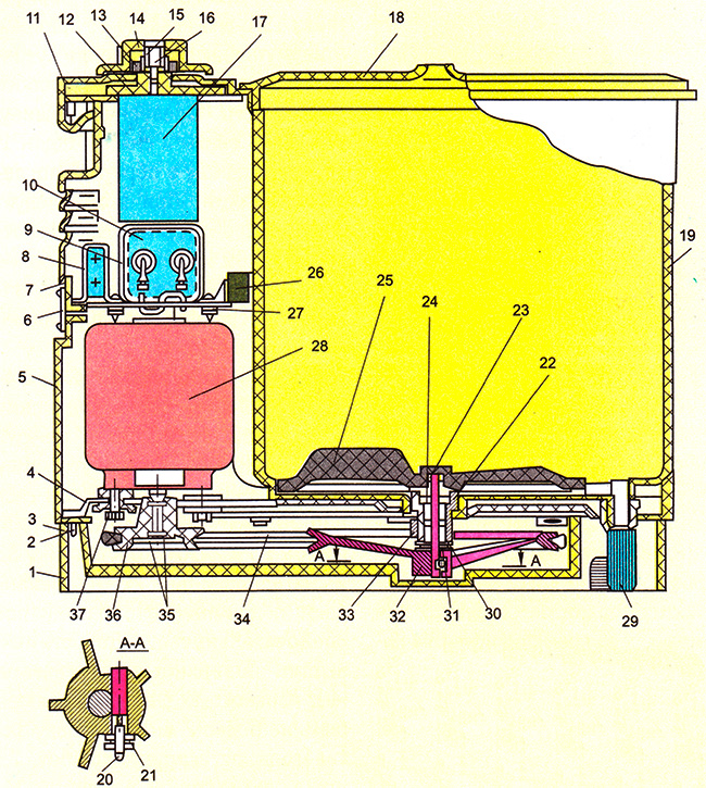
a - construction: 1 - pallet; 2, 6, 12, 16 - screws; 3 - cam; 4 - base; 5 - walls; 7, 9 - clamps; 8.10 - capacitors; 11 - drive cover; 13, 21, 33 - nuts, 14 - handle; 15 - cork; 17 - time relay; 18 - tank cover; 19 - tank; 20 - stopper; 22 - activator bearing; 23, 24, 30, 31 - washers; 25 - activator; 26 - terminal block; 27 - bracket; 28 - electric motor; 29 - hose; 32 - activator pulley; 34 - belt drive; 35 - retaining ring; 36 - engine pulley; 37 - bolt
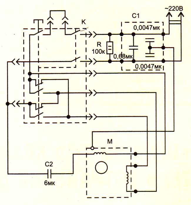
Washing machine Mini-Vyatka SM-1.5 consists of a washing tank 19 (Fig. 1), an electric drive, a tank lid 18, an activator 25 and a connecting cord. The washing tub has a recess in the bottom for installing an activator and protrusions on the inner wall indicating the maximum and minimum water levels for washing and rinsing. The activator is driven by an electric motor through a belt drive 34. The drive of the washing machine consists of an electric motor 28, a time relay 17 and capacitors 8 and 10.The start and stop of the activator drive is carried out using a time relay, the knob 14 of which is displayed on the control panel panel. The washing time is regulated by a time relay from 0 to 6 minutes. Work cycle: 50 s - rotation in one direction, 10 s - break, 50 s - rotation in the other direction, 10 s - break, etc. At the bottom of the machine there is a drain connection with a drain hose 29.
C1, C2 - capacitors, K - cyclic time relay RVTs-6-50; R - resistor; M - electric motor AVE-071-4S
Dismantling the car. Remove the plug 15 (see Fig. 1), unscrew the screw 16 and remove the handle 14. Unscrew the nut 13, remove the drive cover 11, unscrew the screw 2 securing the cam 3 and remove the wall 5 with the electrical equipment. Turn the machine over, loosen the screws and remove the pallet 1. Assemble the machine in reverse order. It should be borne in mind that the permissible gap between the tank 19 and the wall 5 is no more than 0.5 mm. The clearance is adjusted by fixing the cam 3 with the screw 2.
Replacing the actuator bearing... Loosen the motor mounting bolts. Remove the belt 34 from the pulley 32. Unscrew the nut 21 securing the pulley, knock out the stopper 20, remove the activator 25, remove the washers 23 and 24, unscrew the nut 33 and remove the bearing 22. Install the bearing in reverse order. The permissible projection of the activator surface above the plane of the bottom of the tank should be no more than 2 mm. The installation of the activator is regulated by the washer 23 between the activator and the washer 24. The permissible axial displacement of the activator is not more than ± 0.5 mm. The permissible displacement of the groove of the pulley 32 of the activator relative to the groove of the pulley 36 of the electric motor is not more than 1 mm. With a large displacement, adjust the position of the grooves by installing washers 23 and 24. Radial displacement of the pulley on the axis of the activator is not allowed.
Replacing the electric motor... Loosen the bolts 37 securing the electric motor, remove the belt, remove the circlip 35. Use a puller to remove the pulley from the motor shaft. Disconnect electric wires from clamps 26. Remove electric motor. Install new engine in reverse order.
Time relay replacement... Disconnect the electrical wires. Unscrew the screws 12 fastening the relay, remove the relay. Install the new relay in reverse order.
Replacing capacitors... Disconnect the electrical wires. Unscrew the screw b securing the bracket 27 and remove the bracket from the grooves in the wall. Unscrew the screws of the fastening clamps 7 and 9 to the bracket. Remove capacitors. Install new capacitors.
Replacing the belt... Loosen the bolts 37 securing the electric motor to the base. Remove the belt and install a new one. The tension of the femne should be such that the deflection of its branches by 3.4 mm under the influence of a force of 400 gf is provided.
Vyatka automatic machine repair of the lock of the hatch door
The client said that he did not completely drain the water and switched to spinning in a hurry
after that the door went out and the machine stopped working
The hook and door handle remained intact the end switch did not close
The cuff without a collar is simply pulled back and forth.
The top cover needs to be removed, unscrew the lock itself, do not lose the cover
straightened the plate bent the rocker arm
Put the car in place and started working
Krasnoyarsk repair of washing machines t. 8 902 918 93 34
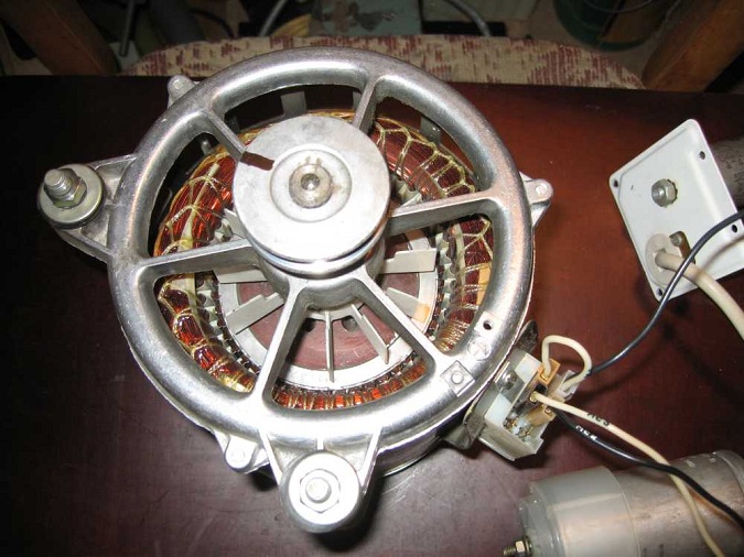
If the washing machine breaks down, and the engine is still running, then it can be used.
It is suitable as an emery sharpener.
Let's figure out how to bring this to life.
It is necessary to find the conclusions of the starting and working windings. The starting winding for starting, for its acceleration. Working winding - works in the load and performs a useful function.
We find two pairs of windings using a tester - multimeter and measure their resistance.
The pair with less resistance is working.
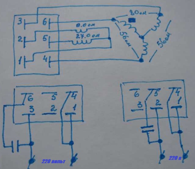
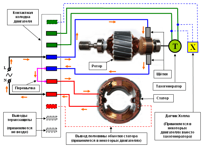
As an example, we give a three-phase asynchronous device from SM Vyatka-Avtomat. There are 6 terminal contacts.
The figure shows the resistance values:
Vyatka's native capacitor is 16 uF, 500 volts.
And the connection diagram to 220 volts:
We recommend that you fix the slider so that it does not damage the connected wires during rotation.To change the direction of movement, we change the terminals of the start winding.
In modern aggregates, there may be more than 6 wire terminals. Approximate scheme:
The third pair is used to measure the speed using a tachometer, which is located on the pulley. For convenience, we connect the starting winding through a capacitor to shift the phase.
After starting, we check it for heating. Your hand must tolerate the heating temperature. Otherwise, the temperature is high and the winding may be damaged.
- bearing wear from incorrect stator and rotor clearance
- got dirt, dust in the brushes
- large capacitor capacity
- turn-to-turn closures
Video (the collector engine is used in Kandy, Indesite, Ariston and so on):
If you ask this question to users of semi-automatic washing machines, they will answer that an activator is a rotating disc on the bottom or wall of the machine's tub that mixes the laundry during washing. We will only add that the blades are located on the outer side of the disc, which is made of plastic. In shape and size, such activators can be different, but their main purpose is the same - to set in motion the contents of the tank.
A modern washing machine also has an activator. A bit strange, but true. In fact, this is a drum rib, as a rule, it is a plastic element that looks like a barrier. It is attached to the inside of the drum, the task of the rib punch is to break and shake the lumps of laundry and thus improve the quality of the wash.
Note! Such an activator also has another function, it plays the role of a drum stiffening rib, protecting this part from damage and strengthening it.
Small washing machines, designed for washing 1-1.5 kg of linen, were in almost every Soviet family. Today they are used by summer residents. Repair of such a machine by a master in most cases is not reasonable, since it can cost half the cost of a new such machine. Therefore, users very often try to fix equipment with their own hands. And I must say that most people do it very well.
Small-sized machines are divided into two types. In some, the activator is located vertically. These machines include "Samara", "Desna". The second type of machines has a horizontally located activator, for example, "Malyutka-425M", "Feya-2" or "Mini-Vyatka". In semi-automatic machines with wringing, the activator is also located horizontally. When parsing such a machine, it also has its own characteristics. Let's consider in turn how to remove and replace the activator in different models of cars.
Cars of this type include "Baby", "Samara", "Otrada". The insides of such machines consist of the main elements: a tank, a cover, a body, an electric motor, a thermal relay, capacitors, and an activator. There is no drum in the activator machine, the function of the drum will be replaced by the activator, which rotates the water in the tank.
To remove the activator, you need to disassemble the machine itself and prepare the key that you need to unscrew the activator. Let's consider making such a key from a cut of a water pipe with our own hands using the example of the "Baby" typewriter. The pipe should be 150 mm longer than the diameter of the activator body. With a 6 mm drill, 2 holes are made in the pipe, the distance between them is 9.5 cm, and the holes will be located symmetrically relative to the center. Then they take two bolts and insert them into the holes, the ends of the bolts should stick out by 10-15 mm. Finally, fasten the bolts with nuts.
Now we will describe how to unscrew the activator:
- We take out the cork in the side of the machine.
- We turn the activator by hand so that the hole in the housing clearly coincides with the hole in the impeller.
- We take a screwdriver and insert it into the motor rotor, thereby jamming it.
- We insert the homemade key into the activator body and unscrew it.
Important! The activator on different machines is unscrewed both clockwise and counterclockwise.
- After removing the activator, take a similar one and assemble the machine in the reverse order.
SM-1.5 machines include "Fairy", "Ivushka", "Mini-Vyatka". Their peculiarity lies in the fact that the rotation of the activator is carried out thanks to the belt transmission. It is not difficult to remove the activator in such machines. Let's list the procedure for the example of the Mini-Vyatka machine:
- After disconnecting the washing machine from the mains, remove the pallet (marked with 1 in the figure).
- Loosen the bolts holding the engine.
- Remove the drive belt (34) from the pulley (32).
- Next, you need to unscrew the nut holding the pulley (21).
- Now, after knocking out the stopper (20), remove the activator (25).
When installing a new activator, one should not forget that the distance between the tank and the activator should not exceed 2 mm, the axial displacement should not exceed 0.5 mm. To adjust the installation of the activator, lay a washer.
Washing machines of this type differ from the previous ones in large sizes and the ability to wash up to 2.5 kg of laundry. The body of a rectangular typewriter is made of metal coated with paint. The activator is usually placed on the side. To remove and replace it, you need to perform the following sequence of actions:
- Unscrew the rear housing cover and remove it.
- Remove the belt from the pulley.
- Remove the bolt holding the pulley to the activator shaft.
- Hold the activator with one hand and remove the pulley.
- Press the shaft together with the activator disc into the washing machine tank.
- Get the activator.
- Assemble the machine in reverse order using a new activator.
- Dismantling the drum is not required in this case. To remove the activator, you will have to remove the drum rim, otherwise it will interfere. We move the plastic clips to the sides and remove the rim.
- Now you need to unscrew the nut holding the activator. It's right at the bottom of the drum, so you need a socket wrench.
- Having unscrewed the nut, we pry the activator with a screwdriver, and then we take it out together with the nut and washer.
- We acquire a new original activator, put it in place of the old one, and then fasten it with a nut.
Note! While unscrewing the nut holding the activator, ask someone to hold the drum so that it does not rotate. Of course, it is possible to jam the drum with a wooden block, but in this case there is a risk of harming the rotation mechanism.
Replacing the fin is not difficult, almost anyone can cope with this task. What do we have to do?
- We take a hard wire (or spring).
- We bend its tip with a crochet.
- We insert the wire into the hole of the rib punch, press on it and push it towards ourselves.
- The rib punch should slide off the retainer and slide off.
- The new drum finisher is put on by hand. We feed the part slightly upwards, and then we put the mating part on the hooks.
- Now the hooks need to be tucked in, for this we take the awl, thread it through the holes in the rib punch and tighten the fixing hooks.
Summing up, we note that you can replace the washing machine activator with your own hands, without the involvement of a specialist. The main thing is to buy an original spare part and take into account all the advice of specialists.Of course, if you are not on friendly terms with the technique and doubt your abilities, invite a master, and he will do everything in a few minutes.
| Video (click to play). |


