In detail: DIY repair of an engine anchor from a real master for the site my.housecope.com.
Content
In many household devices and home-made structures, low-power electric machines are used as a drive. Despite the high reliability of electric motors, their failure for a number of reasons is not uncommon. Given the relatively high cost of these devices, it is more practical to repair them rather than replace them. We suggest considering the possibility of rewinding electric motors at home.
As a rule, collector DC motors and brushless AC induction motors are used in everyday life. It is the repair of these drives that we will consider. Information on the principle of operation and design features of asynchronous and collector machines can be found on our website.
As for synchronous drives, they are practically not used in everyday life, therefore this topic is not touched upon in this publication.
Any type of engine problem can be mechanical or electrical. In the first case, strong vibration and characteristic noise may indicate a malfunction, as a rule, this indicates problems with the bearing (usually in the end cover). If the malfunction is not eliminated in time, the shaft can jam, which will inevitably lead to failure of the stator windings. In this case, the thermal protection of the circuit breaker may not have time to trip.
| Video (click to play). |
Based on practice, in 90% of failure of asynchronous machines, problems arise with the stator winding (open circuit, turn-to-turn circuit, short circuit to the case). In this case, the short-circuited armature, as a rule, remains in working condition. Therefore, even with a mechanical nature of the damage, it is necessary to check the electrical part.
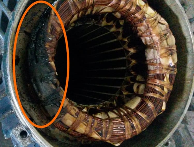
In most cases, the problem can be detected by its appearance and characteristic odor (see Fig. 1). If it is not possible to establish a malfunction empirically, we proceed to diagnostics, which begins with a continuity call. If found, the engine is disassembled (this process will be described separately) and the connections are carefully inspected. When the defect is not found, it is possible to ascertain a break in one of the coils, which requires rewinding.
If the continuity does not show an open circuit, you should proceed to measuring the resistance of the windings, while taking into account the following nuances:
- the insulation resistance of the coils to the case should tend to infinity;
- for a three-phase drive, the windings must show the same resistance;
- for single-phase machines, the resistance of the starting coils exceeds the given indications of the working windings.
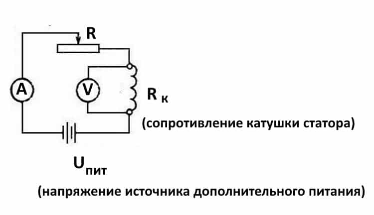
In addition, it should be borne in mind that the resistance of the stator coils is quite low, so it makes no sense to use devices with a low accuracy class to measure it, most multimeters belong to those. The situation can be corrected by collecting a simple circuit on a potentiometer with the addition of an additional power source, for example, a car battery.
The measurement technique is as follows:
- The drive coil is connected to the diagram presented above.
- The potentiometer sets the current to 1 A.
- The coil resistance is calculated according to the following formula: where RTO and UPETE were described in Figure 2.R is the resistance of the potentiometer, is the voltage drop across the measured coil (shown by the voltmeter in the diagram).
It is also worth talking about the technique that allows you to determine the location of the turn-to-turn closure. This is done as follows:
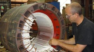
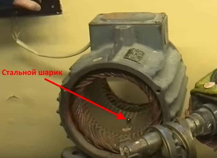
The stator, freed from the rotor, is connected through a transformer to a reduced power supply, after placing a steel ball on it (for example, from a bearing). If the coils are working, the ball will cyclically move along the inner surface without stopping. If there is a turn-to-turn short circuit, it "sticks" to this place.
This type of electric machine is more likely to experience mechanical failures. For example, erasing brushes or clogging the collector contacts. In such situations, repairs are reduced to cleaning the contact mechanism or replacing the graphite brushes.
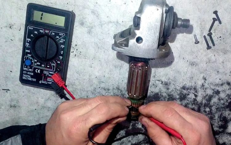
Testing the electrical part is reduced to checking the resistance of the armature winding. In this case, the probes of the device to two adjacent contacts (lamellas) of the collector, after taking the readings, the measurement is made further in a circle.
The displayed resistance should be approximately the same (taking into account the instrument error). If a serious deviation is observed, then this indicates that there is an inter-turn short circuit or an open circuit, therefore, rewinding is necessary.
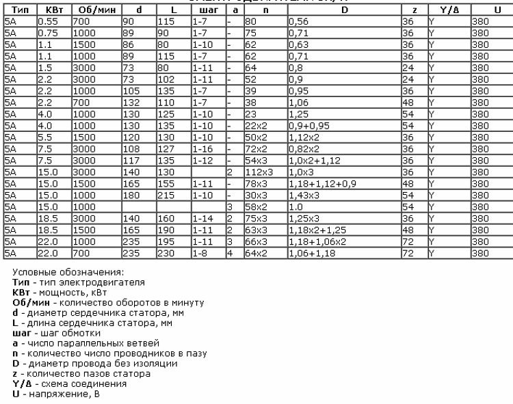
This is a reference data, so the most reliable way to get this information is to consult the appropriate sources. These data can also be given in the passport for the product.
On the net you can find tips in which it is recommended to manually recalculate the turns and measure the diameter of the wire when rewinding. It's a waste of time. It is much easier and more reliable for marking the engine to find all the necessary information, which will indicate the following parameters:
- rated performance (voltage, power, current consumption, speed, etc.);
- number of wires for one slot;
- Ø wire (as a rule, insulation is not taken into account in this indicator);
- information about the outer and inner diameter of the stator;
- number of grooves;
- with what step the winding is performed;
- rotor dimensions, etc.
Below is a fragment of a table with winding data for type 5A electric machines.
It is necessary to immediately warn that without special equipment and work skills, rewinding the coils will most likely be a useless exercise. On the other hand, a negative experience is also an experience. Understanding the complexity of a process is the best explanation of its cost.
We give an algorithm of actions for asynchronous machines, it is as follows:
- Disconnect the drive from the mains (380 or 220 V).
- We dismantle the electric motor from the structure where it was installed.
- Remove the rear cooling fan shroud.
- We dismantle the impeller.
- We unscrew the fastening of the end caps, and then remove them. It is advisable to start from the front part; after dismantling it, the rotor will easily "come out" from the rear cover.
- We take out the rotor.
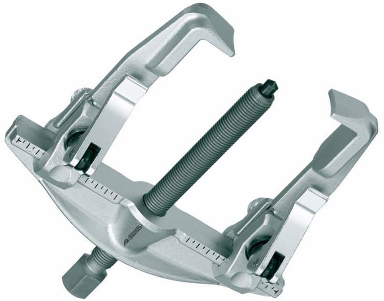
This process can be greatly facilitated if you use a special device - a puller. With its help, it is easy to free the motor shaft from the pulley or gear, and also to remove the end covers.
We will not give instructions for disassembling a collector motor, since it is not particularly different. The structure of this type of electric machine can be found on our website.
The sequence of actions is as follows:
- Using a knife, remove the bandage fasteners and the insulating coating from the wire connections. Some instructions recommend fixing the wiring diagram, for example by taking a photo. There is no particular point in doing this, since this is a reference information and it is not a problem to recognize it by the make of the engine.
- Using a chisel, we knock down the tops of the wires from each end of the stator.
- We release the grooves using a punch of the appropriate diameter.
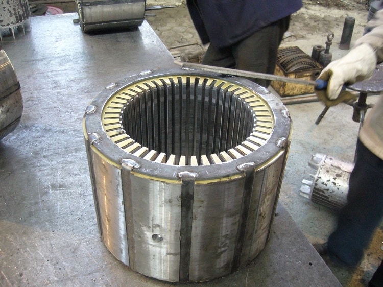
- We clean the stator from dirt, soot, impregnation varnish.
At this stage, we recommend that you stop, take the case and take it to the specialists. Self-dismantling will reduce the cost of restoration work. As mentioned above, it is quite difficult to rewind the coils with high quality without special equipment. To understand the complexity of the process, we will describe its technology, which will facilitate the choice.
The process consists of the following steps:
- Installation of insulators in each groove (sleeve).
- The thickness of the material and its characteristics are selected according to the reference book.
- The winding data is determined by the brand of the motor.
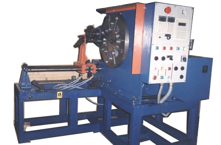
- On a special machine, the required number of turns of the random coils is wound. On the network you can find photos and parameters of homemade hand-held machines, but the quality of their work is rather questionable.
Loose winding machine
- The coil groups are placed in the grooves, after which they are strapped and connected. These processes are quite complex and manual.
- Impregnation is in progress. For this, the body is heated to a temperature of 45 ° C - 55 ° C and is completely immersed in a container with impregnating varnish. It makes no sense to fill the wires with varnish, since in this case there will still be voids left.
- After impregnation, the body is placed in a special chamber, where it is dried at a temperature of 130-135 ° C.
- Final testing of the coils with an ohmmeter.
- Assembly and test run (if only the body was transferred for repair, and the rest of the parts and fasteners).
If only the case was handed over for restoration, we recommend checking the coils before turning on the motor.
The process of replacing the winding of a collector motor is somewhat similar, with the exception of small nuances associated with the design feature. For example, the anchor is sent for rewinding, and not the case, provided that the problem did not arise with the excitation coils. In addition, there are the following differences:
- A special machine of a more complex configuration is used for winding.
- It is imperative to groove, balance the armature (in the final part of the process), as well as clean and grind it.
- Using a special milling machine, the collector is cut.
These processes require special equipment, without it, rewinding of electric motors is a waste of time.
Grinder repair: do it yourself anchor, video, how to check with a tester, rewind the electric motor at home
Grinder repair: 4 main components for repair
Repairing a grinder is not an easy task, you need to know all the subtleties and reasons why the device may fail. For example, repairing an induction motor or a sparking collector is not always within the power of an ordinary person. And then you have to contact the master. In order to understand what the grinder's device is, you need to know how this technique works. With the help of electricity, the engine runs, which transmits rotation to the shaft thanks to the gear. At the end of the shaft there is a cutting or grinding wheel.
The quality of the grinder's work depends on the number of revolutions per minute. A professional tool is capable of developing a speed of 1000 rpm.
The first thing to do in the event of a breakdown is to disassemble the device and clean it, in most cases the grinder starts working.
If this did not happen, you need to understand exactly where the breakdown occurred. The composition of the grinder may differ depending on the model, but the main parts are the same.
When parsing, we can see 4 components:
- The body, which consists of 2 parts;
- Engine;
- Reducer;
- Electrical component.
The motor drives the gear, which in turn drives the cutting element.
Oddly enough, in most cases, the breakdown of the grinders occurs due to the accumulation of dust and as a result of the release of the power button. Therefore, first you need to determine the integrity of the electric drill, its slats and the battery. All this is not so difficult, it is enough to know how the device works. If you once studied the structure of a vacuum cleaner or washing machine, then this will seem like a trifle to you, and a special video can help.
If you are sure that the armature is broken, then you will need to get the electric motor.
Disassembly of the motor must be carried out as carefully as possible. Disconnect all brushes and terminals from power.
Do not forget that before changing the winding, no matter what kind of power tool Bosch, Sparky, Makita, Interskol, you need to manually establish the reasons for the breakdown of the grinder. To do this, you will be helped by the winding and reducer diagram, as well as a special indicator. We take out the rotor, and with it the support bearings and the cooling impeller. All this is a single whole subject. If you notice that most of the wiring is damaged and the balance is out of balance, then it is best to replace this component completely. The fact that the balance is disturbed can be indicated by the appearance of a rumble and vibration in the mechanism.
If the balance of the anchor is not disturbed, and the problem lies only in the reeling, then the anchor must be restored. The work will be to rewind the coil yourself, everything should be done carefully with patience and accuracy. If the balancing of the angle machine works intermittently, then first you need to check it with a tester. In the event that the groove shows different data, it will not be possible to repair the electric motor itself. But a replacement will help to restore it.
In order to replace the rewind in the anchor, you will need:
- New wires for winding should be copper conductors, the diameter of which will correspond to the previous wires;
- Dielectric paper for winding insulation;
- Varnish to fill the coils;
- Soldering iron with solder and rosin.
Before rewinding, you need to count the turns of the wire and apply the same amount in the new winding.
If the problem does not concern the starter, gear, but you find a problem in the winding, then here you will have to purchase copper and enlist the help of a collector puller. To begin with, a continuity tester is carried out, a multimeter will help you to ring, and in order to check the operation of the device, use a short-acting transformer. So you can find the right actions and tools to subdue the grinder.
The process itself consists of the following steps:
- Elimination of the old winding. It must be carefully removed and will not damage the metal case of the anchor itself. If you find any scratches or burrs, they should be ironed out with sandpaper or a soldering iron. Sometimes, in order for the body to be completely cleaned, a burner is used.
- Preparing to connect new wires. It is not necessary to remove the collector itself. It will be necessary to inspect the lamella and measure the resistance of the existing contacts in relation to the case with a multimeter. The indicator should be approximately 0.25 Mohm.
- Elimination of old wires.The remains must be carefully removed and grooves cut in the contacts. Later they will be needed to insert the coil wires.
- Installation of sleeves. The sleeves are made of electrical type cardboard; this is a material whose thickness is no more than 3 mm. The required amount is cut and inserted into the anchor grooves.
- Rewind. The end of the wiring must be soldered to the end of the lamella and wound counterclockwise in a circle. The same action is repeated for all tubs.
- Quality checking. After all the windings are made, use a multimeter to check for short circuits or breaks.
- Final treatments. The finished coil is treated with epoxy resin or varnish. At home, finished work is dried in the oven. You can use a varnish that dries faster.
It may seem like the job is difficult. We hasten to assure you that there is no, however, you will have to spend a lot of time and effort on this.
The anchor is the part on which a large amount of dirt most often accumulates. If the grinder has malfunctions, they can be identified by independently using a multimeter or, in other words, an ammeter.
The check begins with the fact that you need to find the faulty component. If your device is completely out of order, this may be evidence of crumbling brushes or a destroyed layer of dielectric that is between the plates. If you observe sparking inside, it means that the current collectors in the grinder are damaged.
Regardless of what result you get during the examination, you need to check the resistance. It should be the same for each of the measurements.
If the indicators show a deviation, this indicates a violation of the connection of the coils and a poor fit of the brushes.
Pay attention to the brushes, their wear should be the same, and if there are scratches, they must be replaced with new ones. If you did not find any malfunctions, then you need to measure the resistance at the lamella and the coil.
As you could find out from our article, angle grinder is not a complex structure, because it includes only 4 parts. But it is quite difficult to identify the true cause of the breakdown, and as it turned out, most often this is a careless attitude to the tool. To prevent this from happening, take care of your instrument, but if the device is out of order, take the time and follow our instructions to bring it into working order.
The grinder's anchor is most exposed to thermal, mechanical and electromagnetic loads. Therefore, it is a common cause of tool failure, and as a result, it often needs repair. How to check the anchor for performance and fix the element with your own hands - in our article.
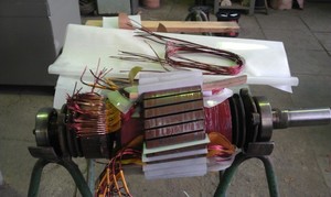
The grinder's motor armature is a conductive winding and a magnetic circuit, into which the rotation shaft is pressed. It has a drive gear at one end and a manifold with lamellas at the other. The magnetic circuit consists of grooves and soft plates coated with varnish to isolate from each other.
In the grooves, according to a special scheme, two conductors of the armature winding are laid. Each conductor is half a turn, the ends of which are connected in pairs on lamellas. The beginning of the first turn and the end of the last one are in the same groove, so they are closed on one lamella.
Types of armature malfunctions:
If the armature is faulty, the motor overheats, the winding insulation melts, the turns are short-circuited. The contacts connecting the armature winding with the collector plates are unsoldered. The power supply is cut off and the motor stops running.
- visually;
- multimeter;
- light bulb;
- special devices.
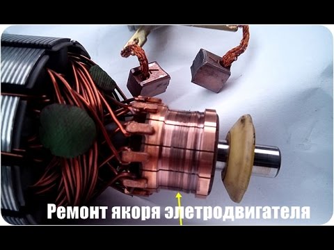
Before taking the device for diagnostics, inspect the anchor.It may be damaged. If the wiring melts, the burnt-on insulating varnish will leave black marks or a peculiar smell. Bent and crumpled turns or conductive particles such as solder residue can be seen. These particles cause short circuits between the turns. The lamellas have folded edges, called cockerels, to connect to the winding.
Due to the violation of these contacts, the lamellas burn out.
Other damage to the manifold: Raised, worn, or burnt fins. Graphite from the brushes can accumulate between the lamellas, which also indicates a short circuit.
- Put a resistance of 200 ohms. Connect the test leads of the device to two adjacent lamellas. If the resistance is the same between all adjacent plates, then the winding is in good order. If the resistance is less than 1 ohm and very close to zero, there is a short circuit between the turns. If the resistance is two or more times higher than average, then there is a break in the winding turns. Sometimes, when there is a break, the resistance is so great that the device goes off scale. On an analog multimeter, the arrow will go all the way to the right. And on digital it will not show anything.
If you don't have a tester, use a 12 volt light bulb up to 40 watts.
- Take two wires and connect them to the lamp.
- Make a break on the negative wire.
- Apply voltage to the wires. Attach the ends of the gap to the collector plates and twist it. If the light is on without changing the brightness, then there is no short circuit.
- Conduct a short to iron test. Connect one wire to the lamellas and the other to the rotor iron. Then with the shaft. If the light is on, then there is a breakdown to ground. The winding closes to the rotor housing or shaft.
This procedure is similar to diagnostics with a multimeter.
There are anchors that do not have visible wires connected to the collector due to filling with an opaque compound or due to a bandage. Therefore, it is difficult to determine commutation on the collector relative to the slots. The indicator of short-circuited turns will help in this.
This device is small in size and easy to operate.
First check the anchor for breaks. Otherwise, the indicator will not be able to detect a short circuit. To do this, measure the resistance between two adjacent lamellas with a tester. If the resistance is at least twice the average, then there is a break. If there is no break, proceed to the next step.
The resistance regulator allows you to select the sensitivity of the device. It has two bulbs: red and green. Adjust the regulator so that the red light starts to light up. On the indicator body there are two sensors in the form of white dots, located at a distance of 3 centimeters from each other. Attach the indicator with the sensors to the winding. Rotate the anchor slowly. If the red light comes on, then there is a short circuit.
The armature checking device determines the presence of a turn-to-turn closure of the winding. An inductor is a transformer that has only a primary winding and a magnetic gap cut out in the core.
When we put the rotor in this gap, its winding starts to work as a secondary winding of the transformer. Turn on the appliance and place a metal plate such as a metal ruler or hacksaw blade on the anchor. If there is a turn-to-turn short circuit, the plate will vibrate or magnetize to the armature body from local oversaturation of iron. Rotate the anchor around the axis, moving the plate so that it lies on different turns. If there is no closure, then the plate will move freely along the rotor.
Due to the anchor, a third of the breakdowns of the screwdriver occurs. With daily intensive operation, malfunctions may occur already in the first six months, for example, if the brushes are not replaced on time. With sparing use, the screwdriver will last a year or more.
The anchor can be salvaged if the balance is not disturbed.If during the operation of the device an intermittent hum is heard and there is a strong vibration, then this is a violation of the balance. This anchor must be replaced. And you can repair the winding and the collector. Small short circuits are eliminated. If a significant part of the winding is damaged, it can be rewound. Grind worn out and heavily damaged lamellas, build up or solder. In addition, you should not undertake an anchor repair if you are unsure of your capabilities. Better to replace it or take it to the workshop.
Over time, the brush develops on the collector. To get rid of it, you must:
-
Grind the manifold using longitudinal cutters, that is, through cutters.
Do not forget to clean the swarf from the rotor to prevent a short circuit.
Before disassembling the armature, write down or sketch the direction of the winding. It can be left or right. To determine it correctly, look at the end of the armature from the collector side. Put on gloves, use sharp cutters or a metal hacksaw. Remove the winding ends. The manifold needs to be cleaned, but it is not necessary to remove it. Carefully, without damaging the slot insulators, knock out the rods of the remaining parts of the winding using a hammer and a metal chisel.
Using a file, without damaging the insulator film, remove the impregnation residues. Count the conductors in the slot. Calculate the number of turns in the section and measure the wire diameter. Draw a diagram. Cut the insulation sleeves out of cardboard and insert them into the grooves.
After winding, weld the leads of the sections with the collector cockerels. Now check the winding with a tester and short circuit indicator. Proceed with impregnation.
- After making sure that there are no problems, send the anchor to the electric oven to warm up for better epoxy flow.
- After warming up, place the anchor on the table at an angle for better flow through the wires. Place a drop of resin on the forehead and slowly twist the anchor. Drip until glue appears on the opposite frontal area.
At the end of the process, lightly grind the manifold. Balance the anchor with dynamic balancing and grinder. Now grind finally on the bearing. It is necessary to clean the grooves between the lamellas and polish the collector. Make a final check for open and short circuits.
The peculiarity of the winding for grinders with a variable speed is that the rotor is wound with a power reserve. The current density affects the speed. The wire cross-section is overestimated, and the number of turns is underestimated.
If the insulation breakdown was small and you found it, you need to clean this place from carbon deposits and check the resistance. If the value is normal, insulate the wires with asbestos. Place a drop on top with Supermoment-type quick-drying glue. It will seep through the asbestos and insulate the wire well.
If you still have not found the place of insulation breakdown, then try to carefully saturate the winding with impregnating electrical insulating varnish. Punched and non-punched insulation will be impregnated with this varnish and will become stronger. Dry the anchor in a gas oven at about 150 degrees. If this does not help, try rewinding the winding or changing the armature.
The lamellas are installed on a plastic base. They can be erased to the very core. Only the edges remain, which the brushes cannot reach.
Such a collector can be restored by soldering.
- Cut the required number of lamellas from the copper pipe or plate to size.
- After stripping the armature from copper residues, solder it with ordinary tin with soldering acid.
- When all the lamellas are soldered, sand and polish. If you don't have a lathe, use a drill or screwdriver. Insert the armature shaft into the chuck. Sand with a file first. Then polish with zero sandpaper. Remember to clean the grooves between the lamellas and measure the resistance.
- There are not completely damaged lamellas. To restore them, it is necessary to carry out more thorough preparation.Slightly whip through the manifold to clean the plates.
To check the anchor of an electric motor at home, firstly, you need to know the basics of electrical engineering. Secondly, it is enough just to carefully examine the anchor and the motor as a whole. If everything is in order, this is good, if damage to the armature itself or the windings is visible, then you should resort to rewinding. Sometimes you need to use a multimeter to "ring" each winding separately for an open circuit, adjacent windings between themselves and the case, in order to determine if there is a short circuit.
Inspection will also give an idea of how to wind the winding, in which direction. Some calculation, taking into account the size and shape of the stator and rotor, grooves and lamellas, will give information about the size of the winding, the number of turns. The cross-section of the wire can be found in the passport data. Otherwise, you can resort to using the Internet or make an appropriate calculation based on the available data: the voltage in the network (220 V), the size and shape of the bases of the electric motor, etc. Also, the motors can be single-phase, three-phase. These parameters must also be taken into account when working. The shape of the windings must also correspond to the original, from the factory:
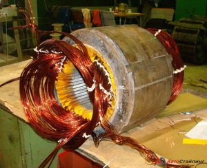
Then you need to wind the windings. The wrapper can do this by hand or use a special machine that can be factory-made or home-assembled. Accuracy is key... Each winding must exactly duplicate the previous one in all respects and be its full replacement. Now it is a responsible procedure - the finished winding must be installed in the grooves in which the insulation has been previously laid. Usually it is cardboard or paper specially designed for electrical appliances.
Each turn of the winding should fit snugly against the other turns. A large gap between them can lead to a discrepancy in motor power as well as an increase in the size of the winding. Then it will be much more difficult to lay the winding into the grooves. Having tightly laid one winding in the corresponding grooves, we proceed to work with the other, and so on in order according to the original scheme, which is better to write down or sketch when disassembling the device.
Sometimes it happens that the wire of the required section is not at hand. Then you can use a wire, the cross-sectional area of which is approximately equal to the required one.Of course, in this case, a calculation will have to be made to find out the exact number of turns for the required engine power and the required level of electricity consumption. With a larger area, the resistance in the wire decreases, and the throughput increases accordingly - more current flows through such a conductor. Therefore, the turns can be made smaller (according to the results of calculations). With a smaller cross-section, there should be more turns than the original.
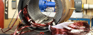
After the procedure for laying the windings, we assemble the electric motor. By the way, the collector must be installed in advance; the soldering of the wires should also be done immediately after laying the winding. A fragment of the shaft between the collector and the armature on one side must be insulated, as well as between the armature and the body on the other side, in order to avoid a short circuit.
- one that is dried naturally;
- for the second type, it is necessary to have an oven for drying at higher temperatures.
Therefore, the second type of varnish is more often used in industry and services, where it is possible and necessary to install such a furnace. If you still chose the second type of varnish at home, and the electric motor is small in size, you can use the oven, setting it to a temperature of 80-90 degrees Celsius.
Next, we perform the verification procedure. First, you need to "ring" the device again, as described at the beginning of the article when diagnosing a problem. It is necessary to exclude the possibility of breakage, lack of contact and short circuit of any kind. If the engine passes these checks, it is time to proceed with the performance check. To do this, do not immediately connect it to the existing power supply. In industrial facilities, the voltage is 380 V. This is quite a lot. Use a step-down transformer to test the operation of the motor.
If it rotates without problems, does not smoke, then the work is done correctly. The engine can be used as intended.
Thus, the instructions for rewinding an electric motor at home are complete. Good luck to everyone in new achievements!
Grinder repair: do it yourself anchor, video, how to check with a tester, rewind the electric motor at home
Grinder repair: 4 main components for repair
Repairing a grinder is not an easy task, you need to know all the subtleties and reasons why the device may fail. For example, repairing an induction motor or a sparking collector is not always within the power of an ordinary person. And then you have to contact the master. In order to understand what the grinder's device is, you need to know how this technique works. With the help of electricity, the engine runs, which transmits rotation to the shaft thanks to the gear. At the end of the shaft there is a cutting or grinding wheel.
The quality of the grinder's work depends on the number of revolutions per minute. A professional tool is capable of developing a speed of 1000 rpm.
The first thing to do in the event of a breakdown is to disassemble the device and clean it, in most cases the grinder starts working.
If this did not happen, you need to understand exactly where the breakdown occurred. The composition of the grinder may differ depending on the model, but the main parts are the same.
When parsing, we can see 4 components:
- The body, which consists of 2 parts;
- Engine;
- Reducer;
- Electrical component.
The motor drives the gear, which in turn drives the cutting element.
Oddly enough, in most cases, the breakdown of the grinders occurs due to the accumulation of dust and as a result of the release of the power button. Therefore, first you need to determine the integrity of the electric drill, its slats and the battery. All this is not so difficult, it is enough to know how the device works. If you once studied the structure of a vacuum cleaner or washing machine, then this will seem like a trifle to you, and a special video can help.
If you are sure that the armature is broken, then you will need to get the electric motor.
Disassembly of the motor must be carried out as carefully as possible. Disconnect all brushes and terminals from power.
Do not forget that before changing the winding, no matter what kind of power tool Bosch, Sparky, Makita, Interskol, you need to manually establish the reasons for the breakdown of the grinder. To do this, you will be helped by the winding and reducer diagram, as well as a special indicator. We take out the rotor, and with it the support bearings and the cooling impeller. All this is a single whole subject. If you notice that most of the wiring is damaged and the balance is out of balance, then it is best to replace this component completely. The fact that the balance is disturbed can be indicated by the appearance of a rumble and vibration in the mechanism.
If the balance of the anchor is not disturbed, and the problem lies only in the reeling, then the anchor must be restored. The work will be to rewind the coil yourself, everything should be done carefully with patience and accuracy. If the balancing of the angle machine works intermittently, then first you need to check it with a tester. In the event that the groove shows different data, it will not be possible to repair the electric motor itself. But a replacement will help to restore it.
In order to replace the rewind in the anchor, you will need:
- New wires for winding should be copper conductors, the diameter of which will correspond to the previous wires;
- Dielectric paper for winding insulation;
- Varnish to fill the coils;
- Soldering iron with solder and rosin.
Before rewinding, you need to count the turns of the wire and apply the same amount in the new winding.
If the problem does not concern the starter, gear, but you find a problem in the winding, then here you will have to purchase copper and enlist the help of a collector puller. To begin with, a continuity tester is carried out, a multimeter will help you to ring, and in order to check the operation of the device, use a short-acting transformer. So you can find the right actions and tools to subdue the grinder.
The process itself consists of the following steps:
- Elimination of the old winding. It must be carefully removed and will not damage the metal case of the anchor itself. If you find any scratches or burrs, they should be ironed out with sandpaper or a soldering iron. Sometimes, in order for the body to be completely cleaned, a burner is used.
- Preparing to connect new wires. It is not necessary to remove the collector itself. It will be necessary to inspect the lamella and measure the resistance of the existing contacts in relation to the case with a multimeter. The indicator should be approximately 0.25 Mohm.
- Elimination of old wires.The remains must be carefully removed and grooves cut in the contacts. Later they will be needed to insert the coil wires.
- Installation of sleeves. The sleeves are made of electrical type cardboard; this is a material whose thickness is no more than 3 mm. The required amount is cut and inserted into the anchor grooves.
- Rewind. The end of the wiring must be soldered to the end of the lamella and wound counterclockwise in a circle. The same action is repeated for all tubs.
- Quality checking. After all the windings are made, use a multimeter to check for short circuits or breaks.
- Final treatments. The finished coil is treated with epoxy resin or varnish. At home, finished work is dried in the oven. You can use a varnish that dries faster.
It may seem like the job is difficult. We hasten to assure you that there is no, however, you will have to spend a lot of time and effort on this.
The anchor is the part on which a large amount of dirt most often accumulates. If the grinder has malfunctions, they can be identified by independently using a multimeter or, in other words, an ammeter.
The check begins with finding the faulty component. If your device is completely out of order, this may be evidence of crumbling brushes or a destroyed layer of dielectric that is between the plates. If you observe sparking inside, it means that the current collectors in the grinder are damaged.
Regardless of what result you get during the examination, you need to check the resistance. It should be the same for each of the measurements.
If the indicators show a deviation, this indicates a violation of the connection of the coils and a poor fit of the brushes.
Pay attention to the brushes, their wear should be the same, and if there are scratches, they must be replaced with new ones. If you did not find any malfunctions, then you need to measure the resistance at the lamella and the coil.
| Video (click to play). |
As you could find out from our article, angle grinder is not a complex structure, because it includes only 4 parts. But it is quite difficult to identify the true cause of the breakdown, and as it turned out, most often this is a careless attitude to the tool. To prevent this from happening, take care of your instrument, but if the device is out of order, take the time and follow our instructions to bring it into working order.

 Loose winding machine


