In detail: do-it-yourself gas 3102 rear axle repair from a real master for the site my.housecope.com.
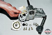
Having taken out the axle shafts, with a “12” key we unscrew ten bolts securing the rear axle housing cover (the upper bolt is longer than the others, it secures the brake pipe bracket).
... and carefully, so as not to damage the gasket, remove the cover.
Using the “12” wrench, unscrew the two bolts securing the locking plates of the differential adjusting nuts.
We mark the position of the differential bearing caps in order to put them in their original places during assembly.
Using the “17” head, unscrew the two bolts securing each cover.
We mark the location of the differential bearing adjusting nuts and the outer rings of the bearings so that they can be put in their original places during assembly.
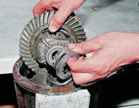
... and take out the differential assembly.
Loosen the pinion nut.
Keeping the pinion flange from turning, unscrew the nut.
We remove the drive gear with an adjusting washer from the rear axle housing.
Use the “14” wrench to unscrew the semi-axle bearing oiler cap and breather.
We assemble the rear axle in the reverse order, after making all the adjustments.
GAZ-31105 - rear-wheel drive, its rear axle is the leading one.
It consists of a beam, inside which all the main nodes are located.
It looks like the rear axle from GAZ 31105
The axle of the driving gear of the axle is located 4.2 cm below the driven one, the gear ratio of the main gear is 4.556, such a gear is called hypoid. The satellite box contains 2 axles, 4 satellites and 2 bevel gears. The body is made of two halves, bolted together.
Drawing of the device of the rear axle of the Volga 31105
| Video (click to play). |
The correct position is set by the adjusting ring located next to it and the bearing. The bearing is preloaded with a spacer ring.
The tips of the axle shafts are inserted into the spline holes of the gears. On the front side of which there are flanges connected to the hub by ten pins. The hub is located directly on the rear axle shaft housing. The wheel is hung and tightened on it.
- The pinion bearing is defective or simply collapsed. This is treated by buying and installing a new one.
- The bearing rings are loose in their niche. Repair or replacement of worn out elements is required.
- Erasing the teeth of the main gear gear - replacing the gear.
- The lateral distance between the teeth of the main gear is broken - repair with the restoration of the previous distance.
- The preload on the pinion bearing has been knocked down. Restore the previous pretension. In case of high output, install a new bearing.
- The driven gear is loose in its lock - tighten the nuts securing the driven gear of the Volga 31105.
- The integrity of the teeth of the main drive gears is broken. Occurs due to a lost gap or poor-quality lubrication of the mechanism. In this case, replacement of both gears of the main gear is required.
It looks like a brake drum for GAZ 31105
In the gearbox of the GAZ-31105 car, it is advisable to change the oil every 30-40 thousand mileage. This will require an old container with a volume of at least one and a half liters, a flat screwdriver, a 12 hexagon and a 30 wrench.
Useful advice! It is recommended to drive 5-10 km before replacing. The bridge oil should warm up to help it drain better.
It is more convenient to perform these actions on a lift or overpass:
- a container for old oil is installed under the gearbox;
- the drain hole is located at the lower rear of the gearbox. A rubber protective seal is removed from it with a flat screwdriver;
- the plug of the drain hole of the bridge is unscrewed with a hexagon by 12, it can stick and get clogged with dirt, so you have to make a certain effort;
and there is.
easier to put an indicator
yes, moreover, it will be better (new technologies


bolts need gazel. Fine Slotted Flange (New)
Thanks for the clarification, everything is clear))) I will try to swap the gears of the axle shafts and assemble them with new rings.
Added after 3 minutes 46 seconds
there are pairs of a new sample (43 by 11) with a large slot, then the flange remains the old one.
I bought pieces of iron:
Pair of 11x43 small splines
Bearings
Flange
But then again the question was found in sales (I traveled to all the stores) only the flange from the gazelle (in the store it was listed as Volgagazelsobol no.) Photo 1.
And he was dear as in photo 2 and 3. The only difference is in the boot (welded on the tin)? Will it fit? And then doubts crept in that it would be rubbing or the removal of the plane under the gimbal is different. Was as needed, just not GAZ, but a remoff, refused to put on the shank at all, the boot can be seen by eye that it was welded quite crookedly 500r. The seller said hammer with a hammer, I thought that if the flange does not move, the bearings cannot be adjusted and sent it 3 letters. He also pushed me for about 20 minutes a bridge for 5000, I say bring a couple, and he told me - think, take a bridge! The GAZ flange is put on by hand but very tightly.
the same trouble, the same work, just decided to move along the beaten track.
The absence of adjusting rings generally pauses the bulkhead for now.

I got up too. Pre-assembled with the old ring a pair gap of 0.17-0.18 mm, the contact patch turned out to be shifted to the outer circumference of the driven gear. I read in the book that it is necessary to increase the thickness of the adjusting ring under the shank bearing. I had a 1.7 mm ring, the thickest in the book 1.75 mm, found, bought, assembled. The spot is now clear in all planes in the middle of the tooth. In the book it is drawn that according to the correct it should be shifted slightly to the inner circumference of the teeth. But there is simply no thicker shim. How to get out of this situation? To order a ring for a turner? Feels like if you put 1.8 mm everything will fall into place. The only thought is that the bearing may be skewed in height. And by the way, before disassembling the bridge, I looked at the contact patch and was also shifted outward of the gear. Maybe something is wrong with the stocking? The previous sole owner said the bridge began to whine slightly under load from the new bridge. There is one more stocking with a faulty gearbox, though without ear under the stabilizer from 3110.
Rear axle - removal and installation
1 - cable; 2 - nut; 3 - equalizer thrust bushing; 4 - equalizer thrust; 5 - equalizer; 6 - rear cable mounting bracket; 7 - bracket; 8 - front cable attachment bracket; 9 - washer; 10 - bolt; 11 - cable guide; 12 - plate; 13 - washer; 14 - nut.
1 - nut; 2 - washer; 3 - gasket; 4 - flange; 5 - bolt; 6 - cardan shaft; 7 - sliding fork.
1 - nut; 2 - washer; 3 - gasket; 4 - bolt; 5 - sliding fork; 6 - cardan shaft; 7 - rear axle; 8 - cross member; 9 - washer; 10 - washer; 11 - washer; 12 - nut.
1 - pipeline from the pressure regulator to the rear brake hose; 2 - bracket for fastening the hose; 3 - stand of the loading spring; 4 - washer; 5 - nut; 6 - loading spring; 7 - tape; 8 - cotter pin; 9 - pipeline to the rear brakes; 10 - rear axle; 11 - clamp for attaching the tube to the rear axle; 12 - tee of pipelines; 13 - washer; 14 - nut; 15 - flexible rear brakes hose.
1 - nut; 2 - nut; 3 - washer; 4 - front bracket pin; 5 - rear axle; 6 - washer; 7 - nut; 8 - earring; 9 - buffer; 10 - stepladder; 11 - clip; 12 - pillow; 13 - spring; 14 - washer.
If at least one of the rear axle parts that affect the size of the mounting size was replaced, then it is necessary to select an adjusting ring of the drive gear shaft.
one.Press pinion shaft bearing outer races into rear axle housing.
2. Install the rear bearing on the drive gear shaft, insert the drive gear into the rear axle housing and install the front bearing.
3. Install the pinion flange. Screw on the nut, turning the shaft by the flange so that the rolling elements of the bearings fall into place. The nut is tightened so that the torque of the new bearings is 1.75–2.25 Nm (0.175– 0.225 kgf · m).
4. Measure the distance A from the end of the drive gear to the rear end of the rear axle housing. Install mandrel 1 190 mm long and 90 -0.01 “lower limit” in diameter into the seats of the differential bearings. Install the differential bearing caps and tighten the mounting bolts to a torque of 90–100 Nm (9.0 - 10.0 kgf · m).
5. Measure the distance B from the mandrel to the rear end of the rear axle housing.
6. Calculate the size M from the end of the drive gear to the differential axis according to the formula M = A - B - D / 2, where A is the distance A from the end of the drive gear to the rear end of the rear axle housing, mm; B is the distance from the mandrel to the rear end of the rear axle housing, mm; D - mandrel diameter equal to 90 mm.
7. Calculate the thickness T of the adjusting ring as the difference between the actual dimension M and the installation dimension of 65 mm. It is necessary to take into account the magnitude of the correction P of the mounting size indicated on the end of the drive gear, with the corresponding sign: T = M - 65 - P, where M is the size from the end of the drive gear to the differential axis, mm; P is the size of the correction to the mounting size, mm. It should be noted that the value of the correction P can be with the sign "+" or "-" and must be substituted into the formula with its own sign, i.e. at the magnitude of the correction with the "+" sign, it is subtracted, and with the "-" sign, it is added.
8. Select an adjusting ring from a repair kit with a calculated thickness (T ± 0.02) mm from 22 groups supplied in spare parts. The group number is indicated on the adjusting ring.
9. Remove the mandrel. Remove the drive gear from the rear axle housing by unscrewing the fastening nut and removing the drive gear flange. Press the rear bearing off the pinion shaft, install the matched shim and press the rear bearing back on.
10. Install the drive gear in the rear axle housing.
11. Select the front bearing preload spacer ring. A spacer ring is installed between the shaft shoulder and the front bearing inner ring. Spare parts are supplied with 47 groups of spacer rings with a thickness of 4.05 to 5.43 mm every 0.03 mm. Select the spacer ring so that the torque of the drive gear shaft bearings is 1.5–2.5 Nm (0.15–0.25 kgf · m) with the flange installed and the nut tightened with a torque of 160–200 N · m (16 –20 kgf · m). When tightening the nut, it is necessary to turn the shaft by the flange so that the rolling elements of the bearings fall into place.
12. After assembling the spacer ring, finally install the front bearing in place.
13. Lubricate the leading edge of the drive pinion flange oil seal and press it in flush with the end of the crankcase.
14. Install the drive pinion flange and tighten the nut of its fastening to a torque of 160-200 Nm (16-20 kgf · m).
15. Install the cotter pin and once again check the torque of the bearings.
16. Install the differential with bearings into the rear axle housing and insert the adjusting nuts into the thread so that they touch the bearings.
17. Install the bearing caps in accordance with the marking and tighten the bolts of their fastening so that the adjusting nuts rotate freely.
18. Install the stand with the indicator. In this case, the indicator leg should touch the tooth surface near the outer end of the driven gear and be directed radially to the tooth surface. Determine the value of the resulting lateral clearance, for which select the clearance between the gears of the main drive by turning at a certain angle to one of the rotation sides of the driven gear until it stops and set the indicator scale to zero.Measure the value of the lateral clearance with the indicator, swinging the driven gear until it stops around the axis in both directions. Measurements should be made at at least eight equally spaced points of the gear. At each measurement, it is recommended to block the drive gear from turning. The side clearance should be between 0.15–0.25 mm. If the side clearance does not fall within these limits, it is necessary to move the gear in the required direction with the adjusting nuts.
On the occasion, the bridge was bought incorrectly called in the common people “Tchaikovsky”, it has nothing to do with Gaz-14;
Advantages:
-Old bolt pattern (5 -139.7)
-Easy GPU adjustment
- Stronger stocking connection, no bolting required
-Differential of a new sample (interchangeability with GAZel)
- The crankcase is tighter towards the central axle (more ground clearance)
Flaws:
-Sump shape, raking in dirt (split bridge cuts through the ground like a plow in both directions equally well)
The internal state is excellent, but from the outside it is all rusty (it is slowly corrected by hydrolysis)
There are plans to install disc brakes from Niva, Patriot or Sobol (not yet decided), differential housing from GAZelle, blocking from Izh-techno and GP 4.1
P / S: prompt the gear ratio of the given gearbox
We assemble the main gear in the reverse sequence to disassembly, lubricating the bearings and gears with transmission oil.
Having installed the drive gear in the gearbox housing, ...
… With a torque wrench, tighten the flange nut to a torque of 16–20 kgf.m, while the gear must be turned to properly install the rollers in the bearings.

We install an indicator with a graduation value of not more than 0.01 mm on a tripod, resting its leg against the end of the flange ...
... and moving the shaft behind the flange, we measure the axial play of the drive gear.

To eliminate the backlash, remove the spacer ring installed on the pinion shaft (see Dismantling the rear axle) and measure its thickness with a micrometer.
We select and install a new spacer ring. It should be thinner than the removed backlash and an additional 0.05 mm thinner if the pinion bearings are new, or 0.01 mm if the bearings are the same.
In the absence of axial play of the drive gear, we check the moment of resistance to the rotation of the shaft with a special torque wrench with a division value of up to 0.5 kgf.m. With correct adjustment, the moment of resistance should be 15–20 kgf.cm for new bearings or 7–10 kgf.cm - if the bearings are left as they were.
With sufficient accuracy, the moment of resistance can be measured with a household steelyard, ...
... by hooking it into the hole in the flange.

In this case, the required values will be less - 3.8–5 kgf and 1.8–2.5 kgf, respectively. If the moment of resistance is greater, we change the spacer ring to another one, thicker by 0.01–0.02 mm, if less, then we select a ring of smaller thickness.
The bolts of fastening parts of the differential box and the bolts of the driven gear, as well as their threaded holes, are degreased and covered with an anaerobic sealant before assembly. We pay special attention to the cleanliness of the end surfaces of the gears and the gearbox of the satellites, the slightest dirt or nicks are unacceptable.
When installing the driven gear on the satellite box, we center it using long M10 × 1 bolts (you can use bolts from old connecting rods).

When installing the driven gear on the satellite box, we center it using long M10 × 1 bolts (you can use bolts from old connecting rods).
Using the adjusting nuts, we tighten the differential bearings with a slight preload, while turning the gear in one direction or the other so that the bearing rollers take the correct position.
To measure the lateral clearance in the meshing of the main gears on the rear axle housing, we fix the indicator by bringing its probe to the top of the tooth on the outside of the driven gear.

The gap should be 0.15–0.20 mm. The measurements should be repeated on at least six teeth in opposite areas of the rim.
To reduce the gap (with a screwdriver or a thin steel rod), loosen the adjusting nut on the side opposite the driven gear, and tighten the other.
Unscrew one nut and tighten the other by the same amount, focusing on the grooves of the adjusting nuts. In this case, each unscrewing of the adjusting nut must be completed by slightly tightening it. For example, to loosen a nut five notches, unscrew it six and then tighten one notch.
This will ensure that the outer ring of the bearing is in constant contact with the nut, thereby ensuring that it is secured during operation.
To increase the gap, repeat the entire procedure in reverse order.
After adjusting the lateral clearance in the engagement, we check the axial play in the differential bearings, for which:
… We fix the indicator on the tripod, resting its probe against the end of the driven gear. Swinging the gear in the axial direction, we measure the backlash in the differential bearings.

Using the adjusting nut located on the opposite side of the driven gear, we set the axial play 0.035–0.055.
Further, tightening the nut, set the bearing preload: 0.1 - when the bearings run less than 10 thousand km; 0.05 - with a run of more than 10 thousand km. Turning the nut one groove corresponds to "compression" of the bearing by 0.03 mm. After adjusting, tighten the bearing cap bolts and install the lock plates (see Rear Axle Disassembly) and re-check the side clearance.
ATTENTION
Before the final tightening of the cover bolts, turn them out one by one and apply an anaerobic sealant to the threaded part.
Adjusting the final drive according to the contact patch of the teeth is an effective way of adjusting the gear engagement. It also allows you to check the quality of adjustments made in other ways.
Apply paint, preferably a bright one, to the teeth of the driven gear.

We turn the flange of the drive gear several times in both directions, at the same time slowing down the driven gear until the paint abrades at the contact points of the teeth.
We examine the contact spots on the teeth of the driven gear from the convex and concave sides.
If the contact patch is located at the top of the teeth, it is necessary to increase the thickness of the adjusting ring at the drive gear, and if at the base, to decrease it.
If the contact patch is displaced to the center of the gear, it is necessary to increase the gap between the driven and driving gears, and if outward, to reduce.
After adjustment, we install the gearbox in the rear axle, while applying a thin layer of oil-resistant sealant to the mounting bolts and flange.
Having assembled the rear axle and filled it with oil (see Changing the oil in the gearbox), we test the gearbox on the fly. To do this, we make a trip at a speed of 60–70 km / h for 20–30 minutes. Heating of the crankcase throat should not exceed 95 ° (water droplets should not boil).
Otherwise, it is necessary to reduce the preload of the pinion bearings.
Contact patch in the final drive gears
A - forward sides;
B - reverse sides;
1 - the correct location of the contact patch;
2 - the contact patch is located at the top of the tooth - to correct, move the drive gear to the driven one;
3 - the contact patch is located at the base of the tooth - to correct, move the drive gear away from the driven one;
4 - the contact patch is located at the narrow end of the tooth - to correct it, move the driven gear away from the driving gear;
5 - the contact patch is located at the wide end of the tooth - to correct it, move the driven gear to the driving gear.
3.362. Place the vehicle on a viewing ditch or lift.
3.363. Remove the decorative rear wheel caps, loosen the wheel bolts, raise the rear of the vehicle, unscrew the wheel bolts and remove the wheels.
3.364. Remove the four bolts securing the rear propeller shaft to the rear axle drive pinion flange and move the rear propeller shaft to one side.
3.365. Lower the parking brake lever to the down position.
3.366. Unscrew the lock nut 1, loosen the adjusting nut 2 and disconnect the two cables 3 of the parking brake drive from the equalizer 4.
3.367. Slide the dust covers 1, unscrew the nuts 2 securing the casings 3 of both cables to the brackets 4 of the body and detach the sheaths of the cables from the brackets.
3.368. Drain the brake fluid from the rear brake circuit into a clean container.
3.369. Disconnect the brake hose from the tee located on the rear axle.
3.370. Unscrew the retaining nut and detach the pressure regulator strut from the rear axle.
3.371. Disconnect the lower mountings of both rear shock absorbers by unscrewing the nuts.
3.372. Unscrew four nuts 1 on each side of the spring ladders and remove the ladders 2, compression buffers 3 and clips 4 with cushions.
3.373. Remove rear axle. This work can be performed by at least two people.
Our additional services and sites:
Rear axle adjustment
The rear axle is adjusted only when replacing the main gears or when eliminating bearing play. Gears are changed very rarely. To eliminate the “howling” of the bridge caused by small scuffing on the teeth, the gears must be replaced, since adjusting such gears only increases the noise of the bridge.
Fig. 130. Semi-axle bearing remover: 1 - press plunger; 2 - semiaxis; 3 - puller bolt; 4 - axis
Rice, 131. Semiaxis bearing locking ring
Rice. 132, Main gear adjustment diagram: 1 and 10 - differential bearings; 2 and 9 - differential bearing shims; 3 - driven gear; 4 - adjusting ring for setting the drive gear; 5 - adjusting washer for adjusting the preload (tightening) of the bearings of the drive gear; 6 - adjusting gaskets; 7 and 8 - drive gear bearings; 11 - sealing gaskets (two); 12 - dirt reflector
It is not recommended to reduce the lateral meshing clearance. Slight slack in the bearings of the gears should be eliminated by adjusting the preload (you must be careful not to disturb the position of each of the gears).
The preload of the bearings of the drive gear is adjusted by changing the thickness of the pack of gaskets 6 (Fig. 132) so that the required preload is obtained after tightening the nut of the drive gear to failure. To reduce the preload, spacers are added, to increase, they are reduced. As a result of the adjustment, the axial play of the pinion gear must be eliminated. After elimination of the axial play of the bearings, the drive gear should be easily turned by hand.
Nut 17 (see Fig. 122) at the end of the adjustment must be tightened to failure (tightening torque 16-20 kgf m). The nut must not be loosened up to the cotter pin. It only needs to be pulled until the hole for the cotter pin coincides with the slot in the nut. Simultaneously with tightening the nut, it is necessary to turn the drive gear so that there is no skewing of the rollers in the bearing. This instruction must be followed, otherwise the bridge may be damaged.
To tighten the nut, in addition to the L-shaped spanner wrench, you must have a fork 0.5 m long to hold the flange when tightening the nut and turning the flange (see Fig. 124). When the nut starts to tighten tightly, after every quarter turn made by the wrench, make several quick swinging movements with the fork so that the rollers take the correct position. If the nut is not tightened sufficiently, the shims are destroyed and an axial play of the drive gear appears.
After adjustment, the bearing temperature must be monitored while driving. When driving for 20-30 minutes at a speed of 60-70 km / h, the heating of the crankcase neck should not exceed 95 ° C (water that gets on the neck should not boil). If excessive heat is present, spacers should be added to reduce preload.
When driving for a long time in hot weather at high speeds, the temperature can exceed 100 ° C.
The preload of the differential bearings is adjusted by changing the total thickness of the packs of spacers 2 and 9 (see Fig. 128), which have the same thickness. -. Increasing the overall thickness of both packs increases the preload of bearings 1 and 10. The preload should be 0.18-0.26 mm. After adjusting the bearings, the driven gear should rotate easily by hand without any axial play or lateral motion. The backlash can be checked through the holes in the crankcase plugs or the throat of the pinion with an indicator.
To make adjustments in the following order: pre-dial a package of gaskets 2 and 9 (each with a thickness of 1.3 mm). Read on the rim of the driven gear the deviation from the mounting distance G. If the deviation has a minus sign, then you should transfer from package 9 to package 2 gaskets, the thickness of which is equal to the deviation, and if the sign is plus, then transfer them from package 2 to package 9
assemble the axle halves without the driving gear (there should be two paper spacers 11 in the crankcase connector):
turn the driven gear; if it rotates tightly and there is no axial play, disassemble the bridge connector and add paper spacers to the connector 11
reassemble the bridge and check the axial play. Add shims 11 until a barely perceptible axial play appears (0.01-0.05 mm);
remove all paper strips and measure their total thickness. Calculate the new thickness of bags 2 and 9; To do this, subtract one third of the thickness of the paper liner from the bag thicknesses available on the differential. Collect the corresponding new bags 2 and 9 and add one 0.15 mm thick spacer to each. Put two gaskets in the connector
Adjusting when replacing individual rear axle parts is easier than adjusting a newly assembled axle. If it is necessary to replace the left half-shaft casing without changing bearing 1 (see Fig. 143), then all gaskets should be kept in place. If the thrust end of the inner ring or the ends of the rollers of bearing 1 are badly worn or the inner ring turns, the bearing must be replaced.
Before installing a new casing, select a new shim pack 2. To do this, compare the distance A on the new and old casing. Measurement should be done by loading the washed bearing and turning it with quick movements in both directions so that the rollers are in the correct position. If the new distance A is larger than the old one, then the package of shims should be increased by the same amount. If the new distance A is less than the old one, then decrease it by the same amount. At the factory, such measurements are made on a special indicator device under load and with rotation.
Before assembling the axle, the bearings should be lubricated with hypoid oil.
Rice. 133. Marking of the main gears: A - serial number of a pair of gears; B - deviation of the height of the drive gear head; B - size deviation (see fig. MZ); G - side clearance in a pair
If it is necessary to replace one or both differential bearings without replacing other parts, then measure the distance A and B, as described above. As a last resort, you can replace the bearings without measurements, but carefully check the lateral clearance in the engagement before and after replacement. The gap should change by no more than 0.1 mm and be at least 0.2 mm when measured at the edge of the dirt deflector 12.
Check if the driven gear rotates easily and if there is no play. If on the first drive off the bridge is found to be noisy, remove it from the vehicle immediately and adjust it.
If you need to replace the differential box, keeping the bearings, then before removing the bearing rings, remember the location of the rings and packs of gaskets in order to put them in their original places and on the new box; check the clearances accordingly.
The pinions of the final drive are replaced only by the kit 24-2402020, selected at the factory for noise and contact patch. The same serial number of the pair is marked on the Highlander of the driving gear (Fig. 133) and on the inner end of the driven gear.
When replacing these gears, it is necessary to put the sludge in a mutual position that simultaneously provides the least noise, correct side clearance and a satisfactory contact patch.
The inner ring of the large bearing should be pressed from the old drive gear using a special puller (see Fig. 126). If the bearings of the drive gear are suitable for operation, then assemble a new gear with old bearings and adjusting rings, and then check the preload of bearings 7 and 8 (see Fig. 132).
If you have to replace the large bearing 8 or both bearings of the drive gear at the same time as the gears, then by selecting the ring 4, you should adjust the position of the drive gear, as indicated below, and then check and, if necessary, adjust the preload of the bearings of the drive gear.
Replacing the small bearing 7 does not require changing the ring 4, but only checking and adjusting the preload of the bearings of the drive gear.
The driven gear should be installed by comparing the mounting distance markings on the new and old gears. If the marking matches and the differential bearings are suitable for operation, then the rings of these bearings and the packs of spacers 2 and 9 under them must be left in place. If the marking does not match, then subtract the old one from the new marking (taking into account the signs). If the result is with a plus sign, shift the package of gaskets 2 of this thickness from the left side of the differential to the right, and with a minus sign - from the right to the left.
If the differential bearings are replaced at the same time as changing gears, the bearing preload should be adjusted as follows before installing the driven gear.
After replacing a pair of gears, check the lateral meshing clearance (Fig. 134). To do this, use the stopper 7820-5089 to securely fix the driven gear through the oil drain hole. Putting the tool 8369-4600 on the flange of the drive gear, determine by the indicator the lateral clearance in the engagement, which should be for new gears within 0.35-0.61 mm of the instrument readings (on the shoulder 60 mm), which corresponds to the clearance in the teeth of 0, 15-0.25 mm.
To check the contact patch, a thin layer of thickly diluted paint (red lead) is applied to several teeth of the driven gear and, in the assembled place, the drive gear is turned several times in both directions (with a small load applied to the brake cables). Disassemble the bridge and inspect the stains on the painted teeth resulting from erasing the paint at the contact points. The size and position of the spot should correspond to Fig. 135.
If the spot does not correspond to the specified one, then the position of the driven or drive gears should be changed by shifting the spacers 2 (see Fig. 132) and 9 or by selecting the ring 4. After that, again check the preload of the bearings of the drive gear, the side play and the contact patch. If only the axle housing is replaced (with the right-hand guard assembly), the differential bearing preload may not be adjusted. If it is necessary to replace the bearings, then replace the packs of gaskets under them, as when replacing the left casing of the axle shaft. When replacing the crankcase, it is imperative to adjust the position of the drive gear and the preload of its bearings.
Rice. 134. Measurement of the lateral clearance in the engagement of the rear axle pair: 1 - stopper 7820-5089: 2 - device for measuring the clearance 8369-4600
Rice. 135. Contact spot of main gears gears: A - forward side; B - reverse side; 1 - the correct location of the contact patch when checking under light load; 2 - the contact patch is shifted to the top of the tooth - to correct it, move the drive gear to the driven one; 3 - the contact patch is shifted to the base of the tooth - for correction Move the drive gear away from the driven one; 4 - the contact patch is too shifted to the narrow end of the tooth - to correct it, move the driven gear away from the driving gear; 5 - the contact patch is shifted to the wide end of the tooth - to correct, move the driven gear to the leading
The position of the drive gear is adjusted as follows.An indicator device measures the distance B (see Fig. 132) from the axle of the differential bearings to the end of the large bearing on the new and old crankcases. During the measurement, bearing 8 must be under the maximum possible load. Before measuring, rinse it and turn it several times in both directions. If the new size B is larger than the old one, then the thickness of the ring 4 should be increased by the same amount, and if it is smaller than the old one, it should be reduced.
Next, adjust the preload of the bearings of the drive gear, and then check the position of the gear, measuring the distance E with an indicator device. The deviation of the height of its head is indicated at the end of the drive gear. If the deviation is indicated with a minus sign, then it must be added to the size 65 mm, and if with a plus sign, then subtract 65 mm from the size to get the size E. The permissible deviation of the size E is + 0.02 mm. If dimension E turns out to be larger than the permissible one, then ring 4 should be replaced with a thicker one, and then again check the preload of the bearings of the drive gear and, if necessary, adjust. If the size E is less than the permissible size, change the ring 4 to a thinner one.
The correct adjustment of the preload of the bearings of the final drive can be made by checking the heating of the axle housing on the bench and measuring the torque of the bearings in the axle after running in the bench.
Heating is determined by the back of the hand when the locations of the pinion gear or differential bearings have become hot, and the rest of the crankcase and cover are still slightly hot (at a drive gear speed of about 3000 rpm, approximately 1 minute after starting). If the hand cannot tolerate touching the indicated areas or the bearing locations quickly heat up immediately after starting, the preload on the respective bearings should be reduced. If the bearing points do not become hot for a long time, increase the preload.
The moment of turning the drive gear of the assembled bridge should be within 20-60 kgf cm; it is recommended to swing the flange back and forth before measuring. If the torque is not correct, remove the axle shafts, remove the drive pinion flange and replace it with a measuring flange, which differs from the usual one in that its surface diameter under the oil seals is 39 mm. Tighten the nut, applying a torque of 16 kgf m, not the cotter pin / i. Measure the cranking torque. It should be in the range of 20-35 kgf cm. If the norm is not met, you should disconnect the covers, remove the differential and measure the torque of the drive gear again. It should be within 10-20 kgf cm. If the torque is not correct, - adjust the bearing tension of the drive gear; if normal, - adjust the differential bearing preload. ,
The above applies to new bearings. If bearings that previously worked in the axle are used, then the rates of the maximum turning moment should be halved (for the drive gear without oil seals, the rate is 8-12 kgf cm).
89
Volga GAZ 3110, 310221 rear axle device repair
The rear axle beam consists of a cast-iron crankcase with a cover and steel pipes-shells of the axle shafts pressed into it from both sides. Flanges are welded to their ends with seating in some places for the bearings of the axle shafts and holes for the bolts for fixing the brake flap.
2 channels are made in the flange. The only one serves to inlet grease to the axle shaft bearing from a cap grease fitting, the second one - to drain oil from the brakes in case of failure of the axle shaft seal.
The main gear is hypoid. The number of teeth of the driving gear is 10, the driven gear is 39. The gear ratio of the reducer is 3.9, The gears are selected in pairs. Differential, bevel gear. It consists of a body in which 2 satellites and two half-axle gears are placed on the axis, which are in engagement with them. The driven gear is bolted to the outside of the differential housing.The base of the differential is located in the rear axle housing on two tapered roller bearings abutting with their ends against the threaded adjusting nuts. The seats of the differential bearings in the crankcase are processed together with their covers, therefore it is impossible to change covers here and there or replace them with covers from another rear axle.
Volga GAZ 3110, 310221 rear axle device repair
Tightening or loosening the adjusting nuts adjusts the differential bearing preload. At the same time, the base of the differential itself moves, which achieves the ability to correct the gearing of the gears.
The pinion gear is housed in the throat of the crankcase in two tapered roller bearings. Its axial adjustment is carried out by the selection of an adjustment ring, and the adjustment of the bearing preload - by adjusting washers.
The half-shaft with its inner end with splines enters the spline opening of the differential half-axle gear, and with its outer end it rests on a bearing pressed into the flange of the half-axle housing.
Transmission oil is pumped into the rear axle gearbox through a threaded opening in the crankcase cover to the level of the lower edge of the hole, and drains through the threaded opening with a plug in the lower part of the rear axle housing.
Rear axle
Sectional rear axle
1 - crankcase;
2 - oiler;
3 - brake shield;
4 - brake drum;
5 - semi-axle bearing;
6 - bushing;
7 - screw;
8 - semiaxis;
9 - felt seal (oil seal);
10 - brake cylinder;
11 - bolt;
12 - axle shaft casing;
13 - semi-axle cuff;
14 - locking sleeve;
15 - crankcase cover;
16 - lock plate;
17 - bolt;
18 - oil filler plug;
19 - satellites axis stopper;
20 - driven gear;
21 - washer;
22 - bolt;
23 - differential bearing;
24 - adjusting nut;
25 - half-axle gear;
26 - satellite;
27 - axis of satellites;
28 - differential case;
29 - leading gear wheel of the main transfer;
30 - drive gear bearings;
31 - cuff;
32 - drive gear flange;
33 - nut.
Removing the rear axle from the vehicle
PERFORMANCE ORDER
Volga GAZ 3110, 310221 rear axle device repair
It is more convenient to work on a lift. Loosen the rear wheel nuts. We hang out the back of the car and remove the wheels.
Disconnect the propeller shaft from the flange of the drive gear of the rear axle (see Removing and installing the propeller drive).
Disconnect the parking brake cables from the equalizer (see Replacing the parking brake cable).
Remove the brake hose (see Replacing the rear brake hose).
Disconnect the brake force regulator strut from the rear axle bracket (see Adjusting the pressure regulator drive).
Disconnect the shock absorbers, remove the ladders (see the corresponding sections of the Rear suspension chapter). Having raised the bridge over the springs, we take it out. The bridge weighs about 85 kg, so you need to do it with two or three people.
Install the bridge in reverse order.
Volga GAZ 3110, 310221 rear axle device repair
Next page""""""
-
1.2.3.4.5.6.7.8.9.10.11.12.13.14.15.16.17.18.19.20.21.
22.23.24.25.26.27.28.29.30.31.32.33.34.35.36.37.38.39.40.
41.42.43.44.45.46.47.48.49.50.51.52.53.54.55.56.57.58.59.60.
61.62.63.64.65.66.67.68.69.70.71.72.73.74.75.76.77.78.79.
80.81.82.83.84.85.86.87.88.89.90.91.92.93.94.95.96.97.98.99.
100.101.102.103.104.105.106.107.108.109.110.111.112.113.114.
115.116.117.118.119.120.121
| Video (click to play). |

